Westell CS17-145-410 Channelized Bidirectional Amplifier User Manual D960 1050 019 r004 MANUAL LOW POWER U7C indd
Westell, Inc. Channelized Bidirectional Amplifier D960 1050 019 r004 MANUAL LOW POWER U7C indd
Westell >
Exhibit D Users Manual per 2 1033 c3
CS17-145-410
Single Band Repeater
LTE-700 Upper C

-2-
This page left intentionally blank.

-3-
Table of Contents
Product Registration Information .................................................................................................... 4
Application .................................................................................................................................. 4
Radio and Television Interference ................................................................................................... 4
Important Safety Information ......................................................................................................... 5
Product Introduction ..................................................................................................................... 5
Band Plan .................................................................................................................................... 5
Feature Overview ......................................................................................................................... 6
Optional Accessories ..................................................................................................................... 6
Important Installation Notes .......................................................................................................... 6
Installation Tips............................................................................................................................ 7
Donor Antenna ............................................................................................................................. 7
Indoor Antennas ........................................................................................................................... 7
Mounting the Repeater .................................................................................................................. 7
Physical System Set-Up Verifi cation ................................................................................................ 8
Controlling the Repeater ................................................................................................................ 8
Software Installation ..................................................................................................................... 8
Directory Location ...................................................................................................................... 10
Installation Status ...................................................................................................................... 11
Starting the Program .................................................................................................................. 12
Status Mode .............................................................................................................................. 13
Control Mode ............................................................................................................................. 14
Specifi cations Section ................................................................................................................. 15
Repeater Photographs ................................................................................................................. 15
Outline Drawing ......................................................................................................................... 16
System Block Diagram ................................................................................................................ 17
RF Specifi cations ........................................................................................................................ 17
Power Specifi cations ................................................................................................................... 18
Mechanical Specifi cations ............................................................................................................. 18
Environmental Specifi cations ........................................................................................................ 18
Alarm Confi guration .................................................................................................................... 18
Alarm Relay ............................................................................................................................... 18
Alarm Interface .......................................................................................................................... 19
Suggested spectrum analyzer setting ............................................................................................ 19
Registration Numbers: ................................................................................................................ 20
One Year Limited Warranty .......................................................................................................... 20
Index ........................................................................................................................................ 21

-4-
Product Registration Information
The serial number may be found on the label on the bottom panel near the power
connectors. Note this number below. Retain this manual, along with proof of pur-
chase, to serve as a permanent record of your purchase.
MODEL NUMBER SERIAL NUMBER PURCHASE DATE
POINT OF SALE COMPANY
DISCLAIMER: All information and statements contained herein are accurate to the best
of the knowledge of Cellular Specialties, Inc. (CSI), but Cellular Specialties makes no
warranty with respect thereto, including without limitation any results that may be
obtained from the products described herein or the infringement by such products of
any proprietary rights of any persons. Use or application of such information or state-
ments is at the users sole risk, without any liability on the part of Cellular Specialties,
Inc. Nothing herein shall be construed as licence or recommendation for use, which
infringes upon any proprietary rights of any person. Product material and specifi cations
are subject to change without notice. Cellular Specialties’ standard terms of sale and
the specifi c terms of any particular sale apply.
This guide should be applied whenever a need exists to add Repeater capability to an existing
system or when this capability is being included with a new installation.
Application
The general safety information in this guideline applies to both operating and service personnel.
Specifi c warnings and cautions will be found in other parts of this manual where they apply, but
may not appear in this summary. Failure to comply with these precautions or specifi c warnings
elsewhere in the manual violates safety standards of design, manufacture, and intended use of
equipment. Cellular Specialties, Inc. assumes no liability for the customer’s failure to comply with
these requirements:
Grounding
This Repeater system is designed to operate from 100-240 VAC and should always
be operated with the ground wire properly connected. Do not remove or otherwise alter the
grounding lug on the power cord.
Explosive Atmospheres
To avoid explosion or fi re, do not operate this product in the presence of fl ammable
gases or fumes.
Lightning Danger
Do not install or make adjustments to this unit during an electrical storm. Use of a suitable
lightning arrester, such as CSI’s model number CSI-CAP, is very strongly recommended.
No User Serviceable Parts Inside
HAZARDOUS VOLTAGES ARE PRESENT WHEN THE COVER IS REMOVED. Opening the
chassis will void your warranty. If you suspect a malfunction with this product, call your dealer or
the Cellular Specialties Support Line at: (603) 626-6677, Toll Free (USA) 1-877-844-4274.
Radio and Television Interference
NOTE: This equipment has been tested and found to comply with the limits for a Class A
device, pursuant to Part 15 of the FCC rules. These limits are designed to provide reason-
able protection against harmful interference when the equipment is operated in a commer-
cial environment. This equipment generates, uses and can radiate radio frequency energy
and, if not installed and used in accordance with the instruction manual, may cause harmful
interference to radio communications. Operation of this equipment in a residential area is
likely to cause harmful interference in which case the user will be required to correct the
interference at his own expense. In order to maintain compliance with FCC regulations
shielded cables must be used with this equipment. Operation with non-approved equip-
ment or unshieled cabled is likely to result in interference to radio & television reception.
Changes and Modifi cations not expressly approved by Cellular Specialties can void your
authority to operate this equipment under Federal Communications Commissions rules.
-5-
Antennas used for the purpose of radiating signals indoors are limited to a maximum gain of 3 dBi. The outdoor antenna used
for the purpose of communicating to the wireless infrastructure is limited to 14dBi gain, or any combination of gain and loss that
equates to 14dB at input. Each antenna must be positioned to observe minimum separation requirements from all users and
bystanders. The following guidelines should be used when considering separation distances.
INDOOR antennas must be placed such that, under normal conditions, personnel cannot come within 20 cm (~0.65 ft.)
from any inside antenna. Adhering to this minimum separation will ensure that the employee or bystander cannot exceed RF
exposures beyond the maximum permissible limit as defi ned by section 1.1310 i.e. limits for General Population/Uncontrolled
Exposure.
OUTDOOR antenna must be positioned such that, under normal conditions, personnel cannot approach closer than 122 cm.
(~4 ft.). A directional antenna having a maximum gain of 14 dBi is used, precautions should be taken to prevent personnel from
routinely passing through the main radiation beam at a distance closer than specifi ed.
Important Safety Information
Product Introduction
Cellular Specialties, Inc. (CSI) developed the CS17-145-410 LTE - 700 U7C repeater for use within enclosed structures where
signal strength from the local cell site is insuffi cient to operate mobile phones. Adequate signal must be available outside the
structure as a prerequisite to achieving in-building coverage. The Repeater is connected via coax cable to an external antenna,
usually on the roof, and to one or more internal antennas placed strategically throughout the area where wireless service is
desired.
The external antenna typically is directional, such as a “yagi”. Internal antennas are typically omnidirectional, although various
other types may be used depending on the coverage application. The Repeater amplifi es both the “uplink” (phone to tower) &
“downlink” (tower to phone) signals thus facilitating communications to and from the intended wireless infrastructure.
With a maximum total of +85dB nominal gain on both the up and down links, gain can be adjusted over a range 30dB in 1.0dB
steps. Control of the repeater is achieved utilizing a computer connected to the NMS 9 pin D-Sub RS323C port. This model is
designed to cover the Upper C portion of the LTE 700 MHz band.
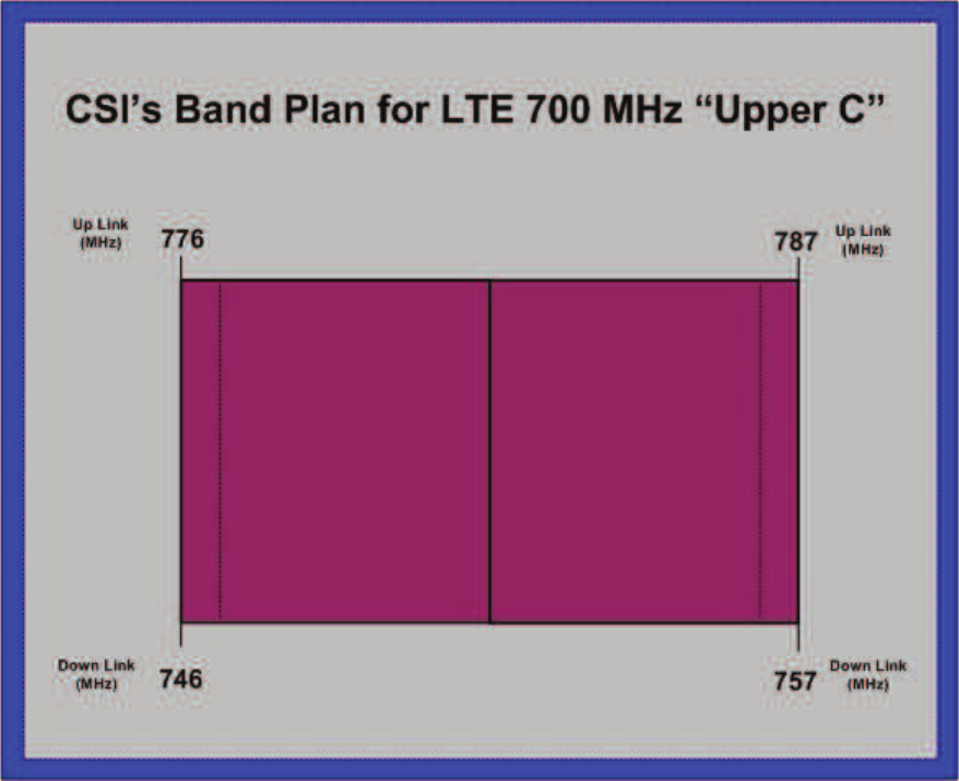
Band Plan
-6-
The CSI-repeater incorporates the following features for convenient operation, access, protection, and control.
• Control using a Windows based Graphical User Interface
and accessed by connecting a laptop or desktop computer
the NMS 9 pin sub-D serial port.
• User Gain Control
• Automatic Level Control
• Automatic Shut Down Function
• Oscillation Protection
• Over Drive Protection
• Under/Over Voltage Protection
• Fault Protection
• Alarm Notifi cation
• External Interfaces - Serial
• Persistent Status and Error information
Feature Overview
A complete line of accessories is available from Cellular Specialties, Inc. Check with your CSI distributor for any additional items
needed. Below are just a few examples suitable for most in-building needs.
•Directional Couplers
6dB - model number: CSI-DC6/700-2.7K/N
10dB - model number: CSI-DC10/700-2.7K/N
15dB - model number: CSI-DC15/700-2.7K/N
20dB - model number: CSI-DC20/700-2.7K/N
30dB - model number: CSI-DC30/700-2.7K/N
•Outside Donor Antenna
Panel - model number: CSI-AP/698/2.7K/7-10
•UPS
Battery backup, 2 hr Single band
1 hour dual band - model number: CS48-985-600
Battery backup, 4 hr Single band
2 hour dual band - model number: CS48-985-601
•Power Dividers
2:1 - model number: CSI-SPD2/700-2.7K/N
3:1 - model number: CSI-SPD3/700-2.7K/N
4:1 - model number: CSI-SPD4/700-2.7K/N
•Grounding Kit - model number: CSI-GKIT
•Lightning Arrestor - model number: CSI-CAP
•Inside Omnidirectional Antenna
Quad-band - model number: CSI-AO/700/2.7K/3
Optional Accessories
• Inadequate isolation between the outside and inside antennas may cause regenerative feedback in the system. This feedback can
cause the amplifi er to emit a continuous signal at maximum amplitude and, in some cases, interfere with normal operation of the donor
site. Careful consideration of the layout and placement of the system is imperative to minimize this possibility and to minimize the amount
of signal leaking from the building. See installation tips for general guidelines.
• The installer should refer to the Safety Guidelines section and the Important Safety Information section for proper antenna selection
and installation. To avoid serious injury or death and damage to the repeater, do not install donor or server antennas near overhead power
lines or high power components. Allow enough distance so that if antennas should fall they will not come in contact with those compo-
nents.
• Close proximity to the donor or server antennas with the repeater in operation may expose the user or installer to RF fi elds that
exceed FCC limits for human exposure.
WARNING! AMPLIFIER OR HANDSET DAMAGE MAY OCCUR IF A HANDSET IS CONNECTED DIRECTLY TO THE REPEATER
OR THE COAX THAT LEADS TO THE REPEATER.
Important Installation Notes
-7-
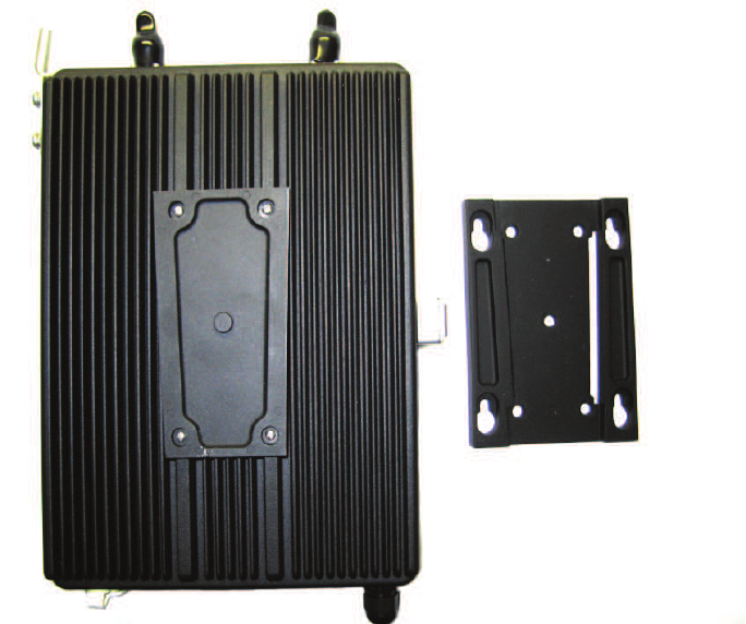
Mounting the Repeater
The following photo illustrates the innovative mounting bracket design that makes wall mounting the repeater
fast and easy.
Donor Antenna
1. Accurately determine the azimuth to the donor site . Obtain the donor site information and approval from the
service provider/carrier.
2. Ensure that the radiation path to the donor site is as unobstructed as possible.
3. Mount the donor antenna at or toward the edge of the roof, in the direction of the donor site. Try to avoid having the RF
signal from the donor pass above the location(s) of the service antennas. Normally the service antennas will be behind
and below the donor antenna if viewed from above. This approach will help avoid interference and feed back both, to and
from the service antennas.
4. Normally mounting the donor antenna higher will allow a less obstructed path to the donor site. However, in high traffi c
metro areas avoid mounting the donor antenna any higher than necessary as the quality of the donor signal may start to
become less stable and it is more likely to encounter adjacent channel interference.
5. When possible shield the donor antenna’s back side by locating it so that any HVAC units and/or penthouse structures are
behind the antenna relative to the donor cell site location.
Installation Tips
Indoor Antennas
1. Use omnidirectional antennas (see optional accessories) indoors, and locate them centrally with respect to the intended
coverage area to minimize signal leakage to the outside. Use directional antennas indoors only in special cases when higher
gain and directionality would be helpful and RF exposure limits will not be exceeded.
2. To avoid repeater uplink overload and gain limiting mount the indoor antennas away from areas where mobile subscribers
frequently use their phones such as desks or dispatch areas.
3. To determine the quantity and locations of indoor antennas, use an appropriate phone’s signal meter to determine areas of
weak signals. These are the approximate areas where indoor antennas may be needed. Also be aware the signal from an
indoor antenna, in most cases, can be expected to penetrate about two standard offi ce sheetrock type walls to reach users.
After two walls or if the walls are made of other materials, it may be necessary to split the available signal and add more
antennas.
1. Using the detachable bracket as a
template, mark the locations for the
wall anchoring system.
2. Drill holes, install wall anchors
and lock the wall mount bracket in
place.
3. Slid repeater into receiver rails of
the wall mount bracket.
Note: The wall anchoring system
selected will depend on the material
used in the wall where the repeater
is to be mounted. It will need to be
capable of supporting the weight of
the repeater (12.2 lbs / 5.5 kg) and
all the cabling attached to it.
-8-
All cables should be checked for shorts and opens. Also verify that there are no cables with loose or poor connections. RF leakage could
cause oscillation to occur under some conditions.
The rooftop antenna (Donor Antenna), if directional, should be checked for proper alignment along the calculated compass heading.
Typically, the directional antenna would be aimed at the same site that your handset uses, but it may not always be so. It is critical the
installer contact the service provider for information on, and approval of, the site he or she has selected before
the system is turned on.
If cables and alignment are acceptable and a problem persists, it may be necessary to use a spectrum analyzer to examine the signal
environment in which the unit is operating. The existence of strong adjacent channel signals within the frequency band(s) can cause the
AGC to reduce the amplifi er’s gain or cause alarms. In some cases additional fi ltering or attenuation might be required to reject these
unwanted signals. In some instances, the donor antenna can be reoriented horizontally, to place the interference source in an antenna
pattern “null”. There also may be some cases where the interference from outside signals is so great that they cannot be fi ltered or oth-
erwise reduced or eliminated without expensive and possibly prohibitive measures. In these cases it may not be practical to use the CSI
repeater for providing coverage to these sites.
Physical System Set-Up Verifi cation
Controlling the Repeater
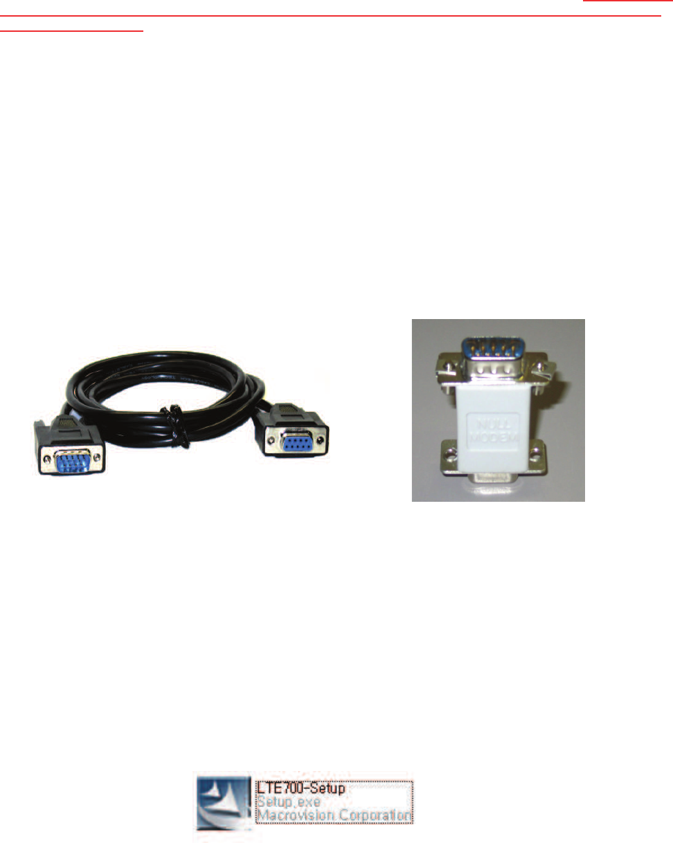
Control and monitoring of the repeater requires that a properly confi gured computer, with CSI’s LTE700 control software
installed, be connected via a serial cable (optional), as shown in fi gure 1, from the serial connector of the computer to the serial port
labeled NMS on the bottom end panel of the repeater. If the gender of the connector is not the same as shown in fi gure 1, a null modem
adapter (optional) as shown in fi gure 2 may also be required. If your computer does not have a serial connector, a USB to Serial Adapter
may be a option for you.
Figure 1 Figure 2
Software Installation
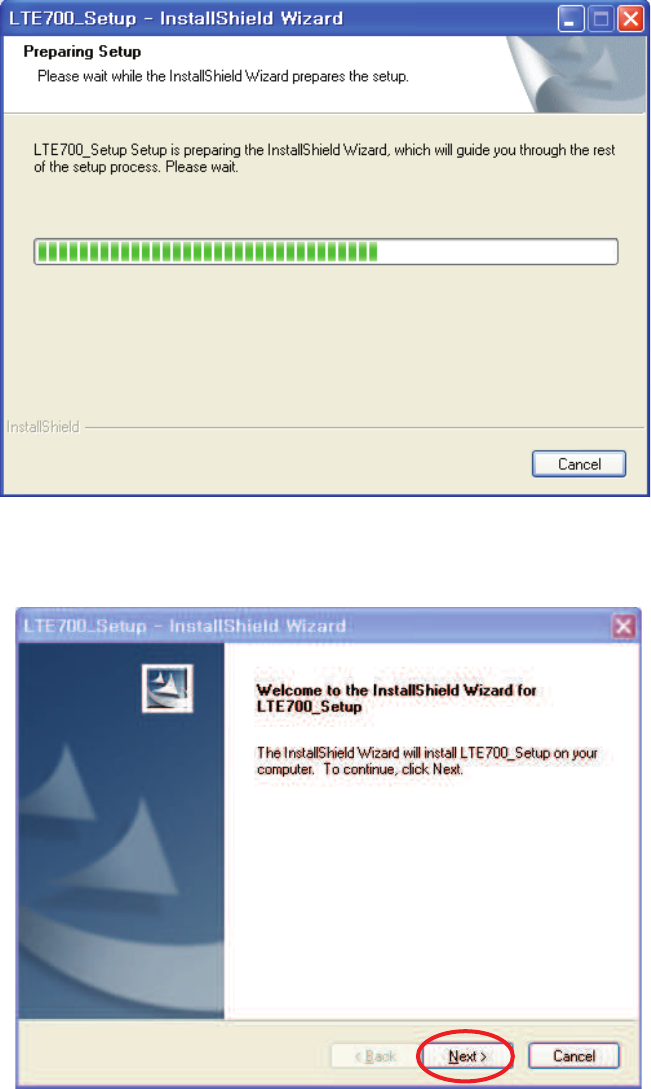
Locate the Software CD that came with the repeater and insert it into your CD drive. Browse the CD and fi nd the
LTE700-Setup fi le and double click on it.
Note: It may be necessary, in the System Properties section of the control panel; using Device
Manager to determine what COM port your computer uses for the communications port. In many cases it’s COM 1.
-9-
The following screen will be displayed showing the set up progress status.
When the Install Shield Wizard has completed preparing setup, click next and
you will be given the option to install to the default directory or choose another
directory.
-10-
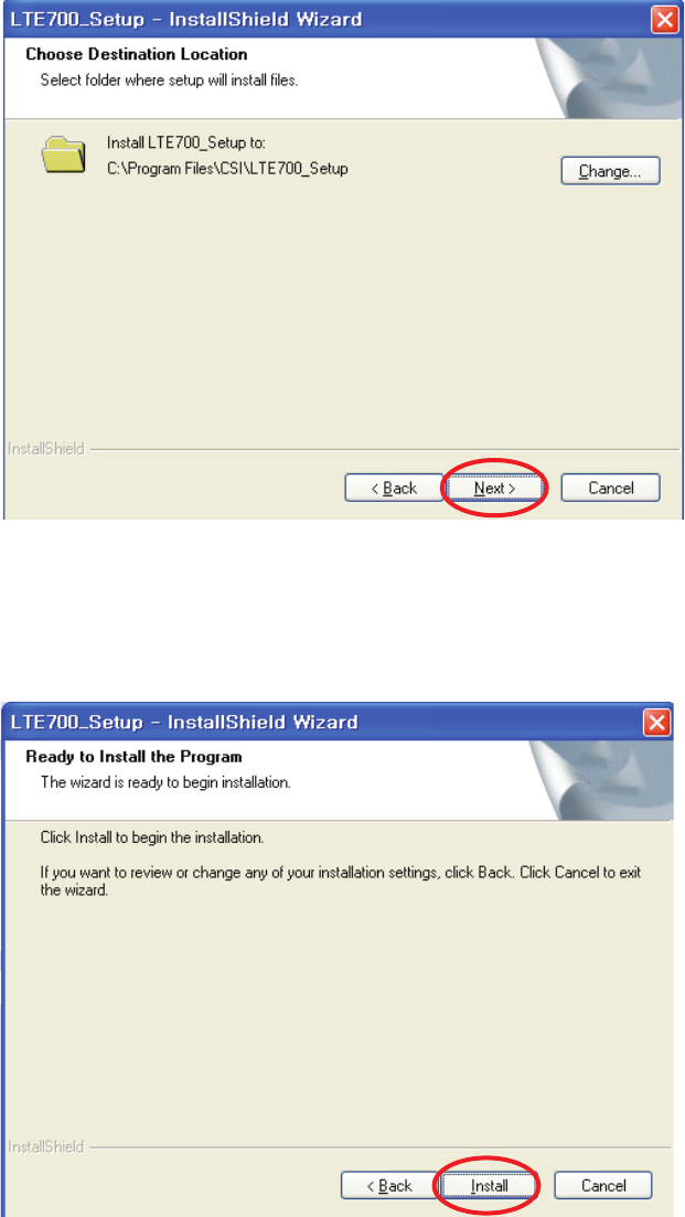
Once the directory where the program is to be installed has been selected, click
next to continue the installation.
You will be given the option to review or change settings using the back button.
If you’re satisfi ed with the settings click Install.
Directory Location
-11-
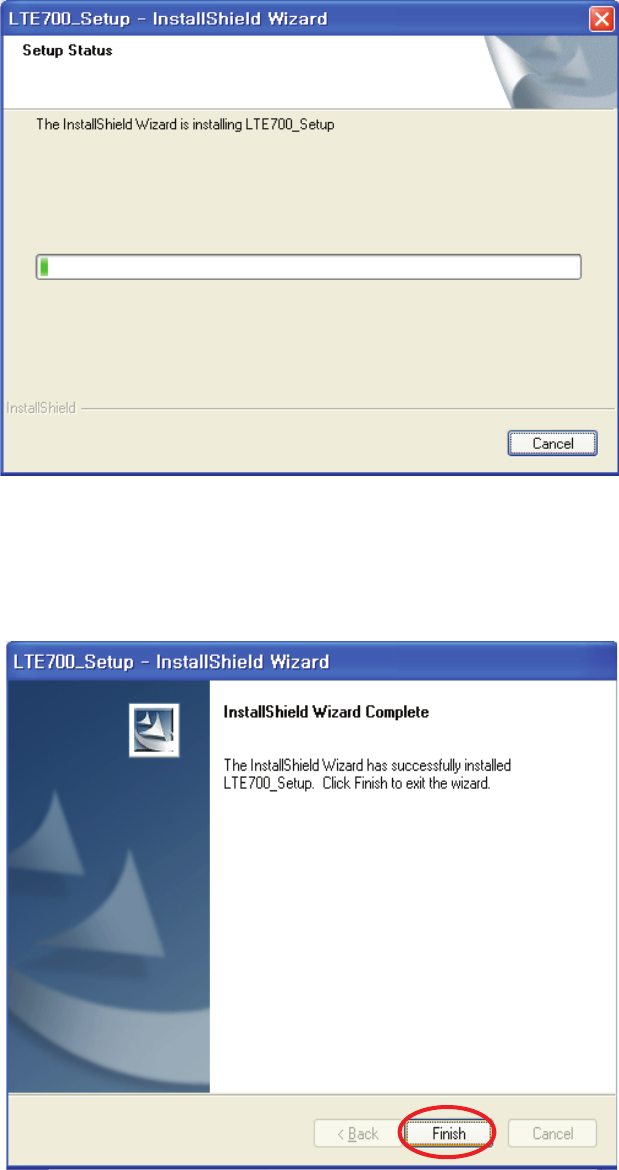
During the install process the Setup Status screen is displayed, showing the
progress of the software installation. When complete click fi nish to close the
install wizard and begin using the software.
Installation Status
-12-
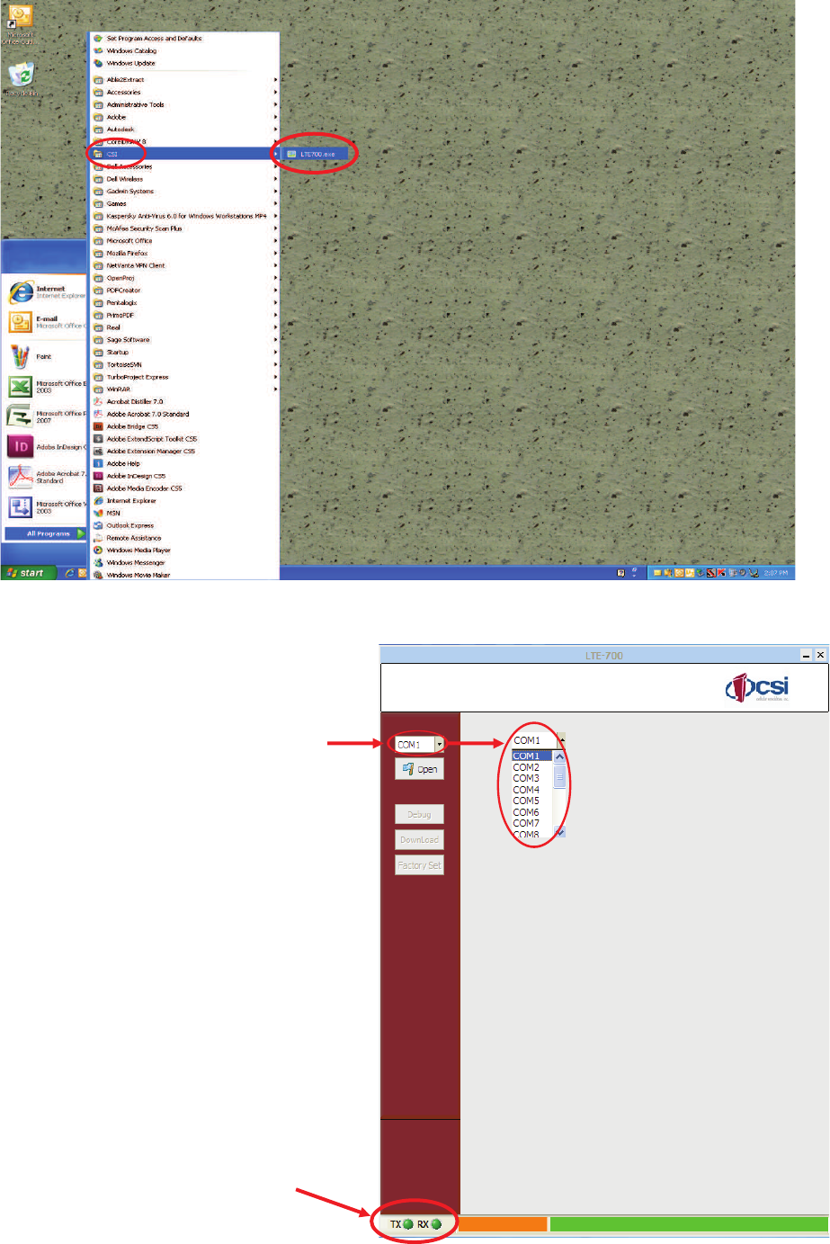
When the LTE700 software installation is complete the program may be launched
by clicking start >CSI>LTE700.exe
To confi gure the LTE700
software to communicate
with the repeater, click the
down arrow to the right
of “COM port” selection
box. A fl y out menu will
be displayed and allow the
user to select the COM port
confi gured for use on the
controlling computer.
When the “COM port” has
been selected the pro-
gram will interface with the
repeater and the TX and
RX indicators will illuminate
green. If red, check the COM
port settings on the computer
and that the correct COM port
has been selected in the fl y
out above.
Starting the Program
-13-
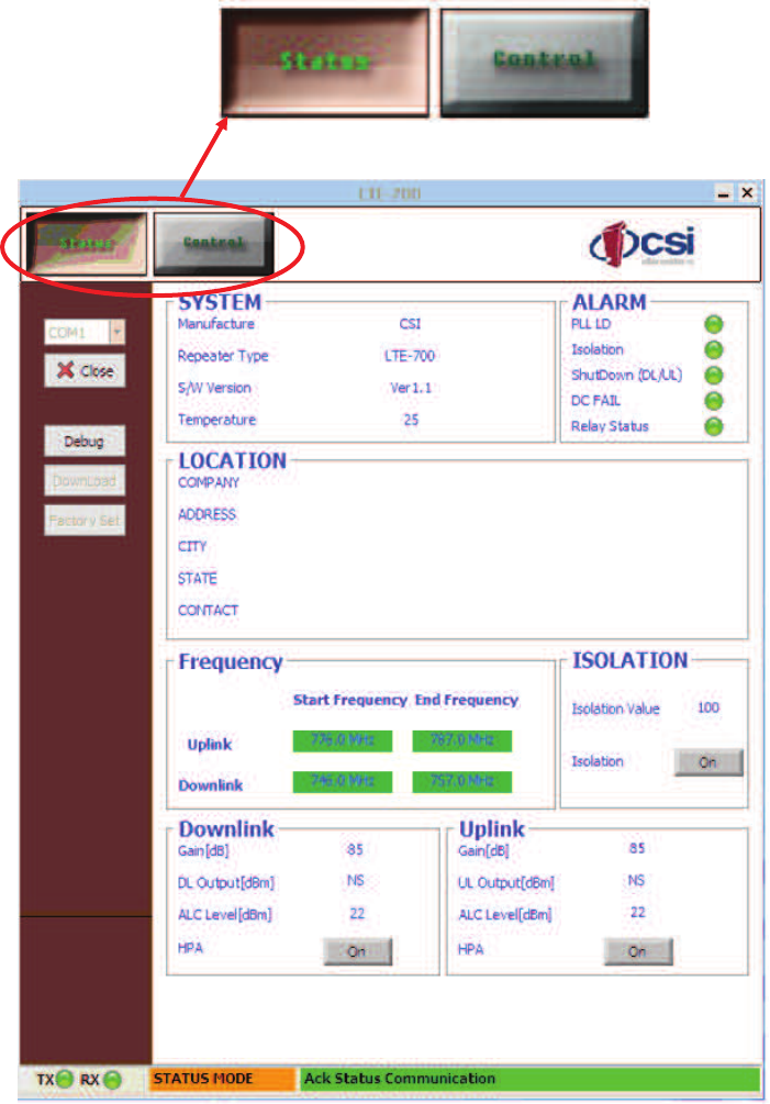
Status Mode
The LTE700 repeater control software features three modes of operation, Status Mode, Control Mode and Management
mode. Selecting the Status Mode by clicking the Status button allows the user to review the system settings for seven main
categories.
The SYSTEM box displays Manufacturer, Repeater Type, S/W Version and current Temperature.
The ALARM section notifi es the user if alarm conditions exist for PLL LD, Isolation, Shut Down (DL/UL), DC Fail and Relay
Status. Green indicates a normal condition is present, if illuminated Red an alarm condition exists.
The LOCATION box will show the address information set by the user, if a new installation, it will be blank but can be popu-
lated by entering the Control Mode which will be covered later in this manual.
The box for Frequency shows the user start and stop frequencies for uplink and downlink.
Isolation value and enable status can be viewed in the box labeled ISOLATION.
Finally the Downlink and Uplink sections show Gain, Output(dBm), ALC Level(dBm) and HPA enable status for there respec-
tive links.
-14-
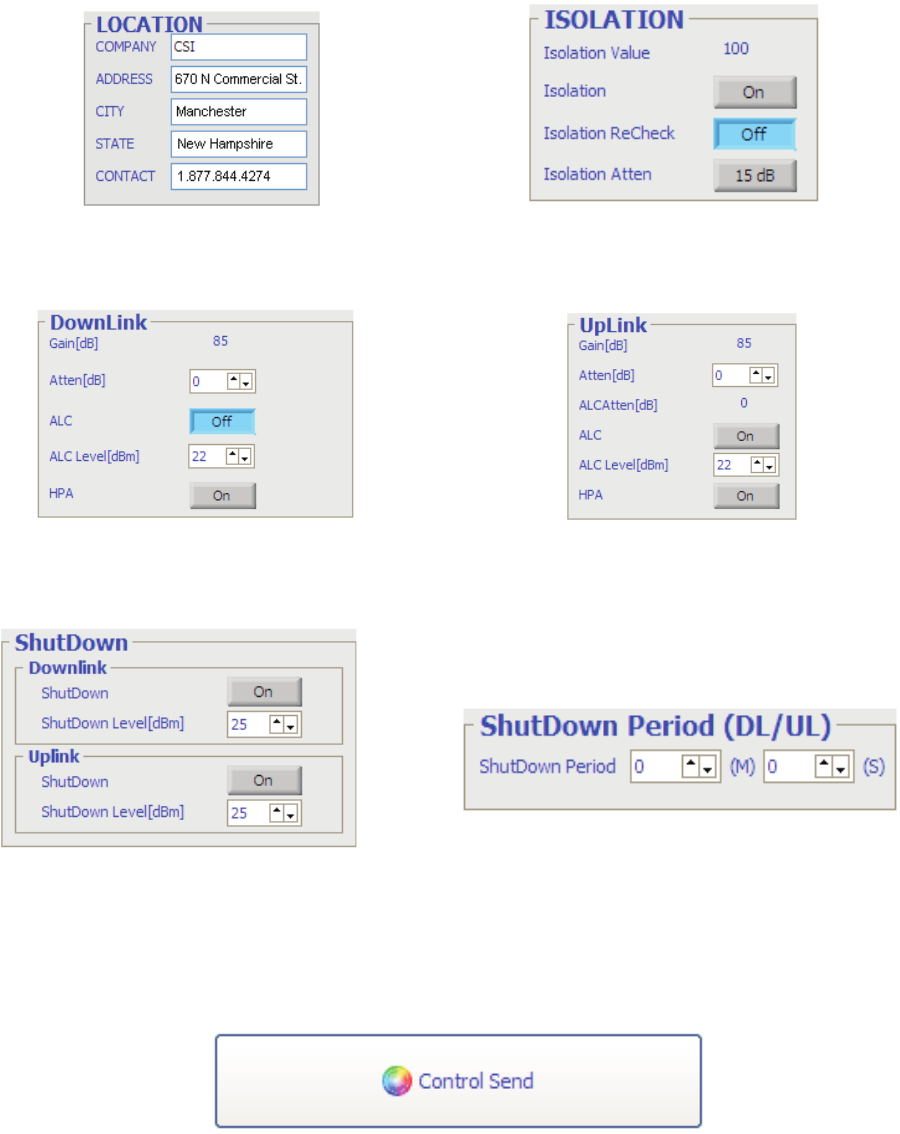
Control Mode
Selecting the Control Mode by clicking the Control button will display a similar user interface to the one used in the Status
mode but allows the user to change the system settings described in the previous section.
In this mode the user may make changes in the sections shown below.
When the user has completed modifying all the fi elds he or she would like to change it is necessary to click the Control
Send button to incorporate them into the repeater. Note: The changes will not take affect until they are sent to the
repeater.
-15-
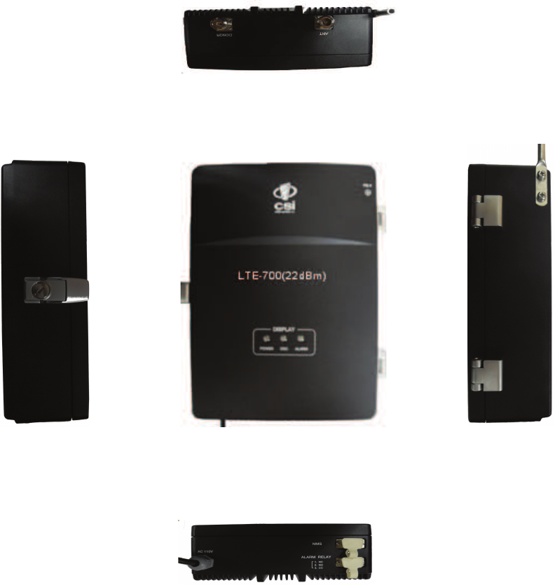
Specifi cations Section
Repeater Photographs
-16-
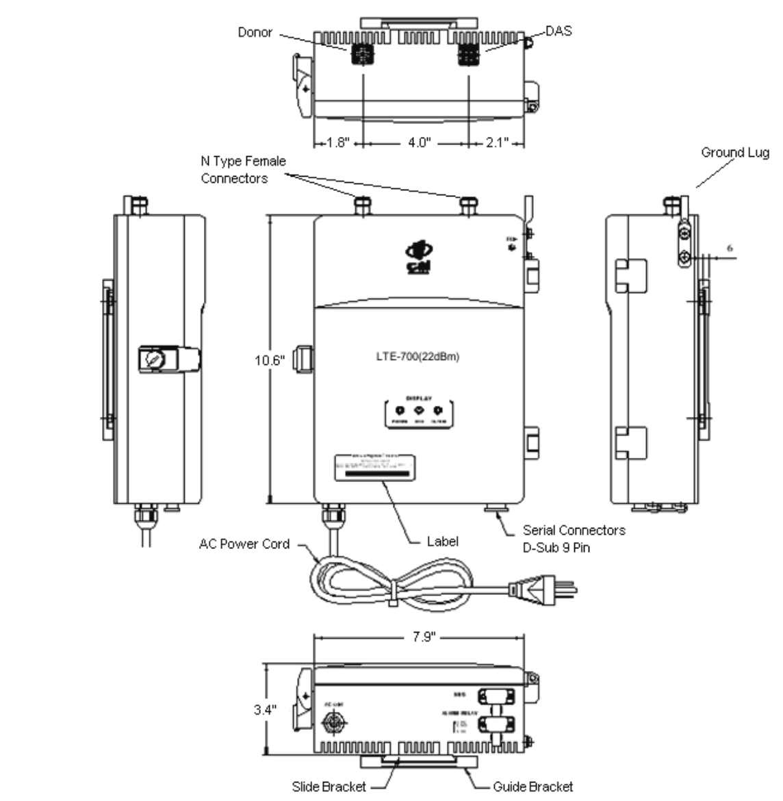
Outline Drawing
-17-
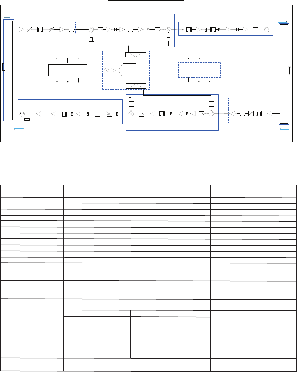
LTE - 700 Block Diagram
PLL
UP LINK
UP LINK
C P U
Power Supply
(DC 6V, 24V)
LNA
1st Mixer
IF SAW RF SAW
Thermistor
ALC
(0~25dB)
LNA Gain ADJ IF SAW Thermistor HPA
1st Mixer 2
nd
Mixer
AGC
(0~30dB) Coupler Isolator
DOWN LINK
ALC
(0~25dB)
Isolation
Check ATT
HPA
Isolator Coupler
2
nd
Mixer
Thermistor Gain ADJ
DET
RF
SAW
Up Do nw Con v er t or(UL) HPA Dr i v e A MP( UL )
Up Do nw Con v er t or(UL)
DOWN LINK
Up Do nw Con v er t or(DL)
LNA / A L C( DL )
HPA Dr i v e A MP( DL )
CPU
PS U PL L
DET
System Block Diagram
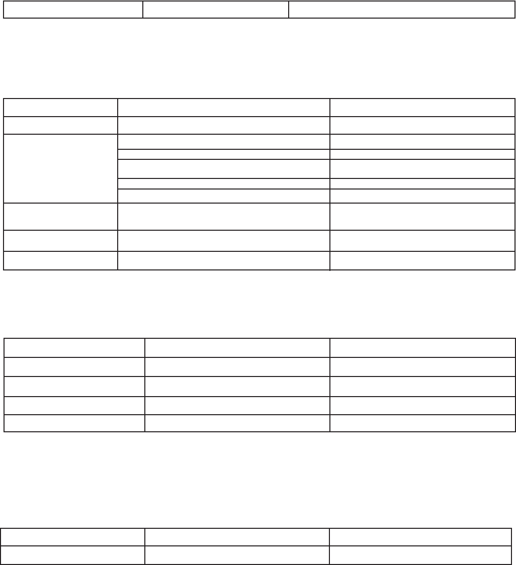
RF Specifi cations
ITEM Specifi cation
FREQ. RANGE UL 776~787MHz
DL 746~757MHz
Frequency Selectivity UL / DL @-40dBc ±2MHz
Gain UL / DL 85dB(±1.0dB)
Gain Adjustment Range UL / DL 30dB/30dB(±1dB, 1dB step)
ALC Range UL / DL 25dB / 25dB(±1dB)
Pass Band Ripple UL / DL ±1dB(Peak-To-Peak 2dB)
Linear Output Power UL / DL +22dBm
1dB Gain Compression UL / DL 26dBm
Input VSWR UL / DL < 2:1
Propagation Delay UL / DL 3us
Frequency Error UL / DL < ±0.01ppm (± 7.5Hz)
EVM UL / DL DL : 8% , UL : 12%
Out of Band Gain 1.0≤f_offset_CW<5.0MHz 45 dB
5.0≤f_offset_CW<10.0MHz UL/DL 45 dB
10.0MHz≤f_offset_CW 35 dB
Operating Band
Unwanted 5.05MHz≤f_offset<10.05MHz UL/DL -14dBm
Emission 10.05MHz≤f_offset<f_offsetmax -13dBm
ACRR ± 5MHz
± 10MHz UL/DL 20dB
DL UL
9 ~150kHz 9 ~150kHz
150 ~ 30MHz 150 ~ 30MHz
Spurious Emission 30 ~ 740MHz 30 ~ 770MHz -13dBm
760 ~ 1GHz 790 ~ 1GHz
1GHz ~ 12.75GHz 1GHz ~ 12.75GHz
Noise Figure UL < 6.5dB @Max. Gain
-18-
Power Specifi cations
Parameter Specifi cation Remark
Main Power Input Voltage AC110V @0.7A Internal AC DC Power Supply
Mechanical Specifi cations
Parameter Specifi cation Remark
Size (Inch) 7.9” x 10.6” x 3.4” (L x H x D)
Size (mm) 200 x 270 x 86.5 mm (L x H x D)
Link/Service Antenna Ports N – female
AC Power In AC cord 4.9 ft (1.5M)
Connectors Frame Ground External grounding
point to be provided
RS232C (External) 9 Pin D-SUB, female
Alarm (External) 9 Pin D-SUB, female
Mounting Type 2 part Wall Mounting Bracket Repeater plate section slides
into wall bracket.
Enclosure Lock Key Lock
Heat Dissipation Natural Convection
Environmental Specifi cations
Parameter Specifi cation Remark
Operating Temperature (F) 14°F ~ +122°F (ambient) Indoor
Operating Temperature (C) -10°C ~ +50°C (ambient) Indoor
Storage Temperature (F) -22°F ~ +131°F (ambient)
Storage Temperature (C) -30°C ~ +55°C (ambient)
Humidity 95%
Alarm Confi guration
Alarm Relay
Shutdown Signal Relay Status Remark
High NO + CC 1 NC, 2 NO, 3 CC
Low NC + CC

-19-
Repeater LED Condition/Troubleshooting
POWER ISO ALARM
GREEN RED RED Power Supply has failed or unit is unplugged.
Off Off Off
GREEN RED RED Checking status.
Blinking Blinking Blinking
GREEN RED RED Normal condition at Power Up
Solid Off Off
GREEN RED RED
Solid Solid Off
GREEN RED RED
Solid Off Solid
GREEN RED RED PLL Lock Detect Fail Alarm.
Solid Off Blinking
GREEN RED RED Repeater is off line. Contact Customer Service.
Blinking Off Off
Alarm Interface
Insuffi cient isolation exists between the donor
and DAS antennas. Turn off power. See Installa-
tion Tips section. The Donor and DAS antennas
may need to be adjusted or relocated to obtain
suffi cient isolation.
Shut-Down Alarm. Received signal from donor source
is too strong (Exceeding AGC range). Relocate or
attenuate donor antenna to reduce received signal.
When troubleshooting RF issues, and when surveying challenging RF environments, it’s important to have a spectrum
analyzer capable of measuring the frequency that you are working with. An attenuator should be used to protect
the input, when connected to a source of RF power such as the repeater or a powered DAS.
Both Uplink and Downlink should be measured. Downlink should be measured on the donor cable and at the output
(server) port of the powered up repeater, and Uplink at the lead from the DAS (on fi ber/powered DAS’s, where the
lead would connect to the server port on the repeater) and at the donor port with the repeater powered up. Mea-
surements may also be necessary at server antenna locations. Your spectrum analyzer will need to be equipped
with a whip antenna for this.
Resolution Bandwidth (RBW) should be set at 200 kHz for GSM and 1 MHz for CDMA. If you cannot select these val-
ues, the closest available values should be used. Video fi lter should be about one tenth of RBW. Other settings like
span are whatever is appropriate. One should also make sure that there are no signals above the top of the screen.
If you cannot see an adjacent out of band signal when using the 1 MHz RBW fi lter, you can decrease the RBW, to
see the close-in-frequency signals. Be sure to set the RBW back when you want to measure the power level.
Suggested spectrum analyzer setting

-20-
Seller warrants that its products are transferred rightfully
and with good title; that its products are free from any law-
ful security interest or other lien or encumbrance unknown
to Buyer; and that for a period of one year from the date of
installation or fi fteen months from the date of original ship-
ment, whichever period expires fi rst, such products will be
free from defects in material and workmanship which arise
under proper and normal use and service. Buyer’s exclusive
remedy hereunder is limited to Seller’s correction (either at
its plant or at such other place as may be agreed upon be-
tween Seller and Buyer) of such defects by repair or replace-
ment at no cost to Buyer. Transportation costs in connection
with the return of products to Seller’s plant or designated
facility shall be paid by Buyer. The provisions of this warranty
shall be applicable with respect to any product which Seller
replaces pursuant to it. SELLER MAKES NO WARRANTY,
EXPRESS OR IMPLIED, OTHER THAN AS SPECIFICALLY
STATED ABOVE. EXPRESSLY EXCLUDED ARE THE IMPLIED
WARRANTIES OF MERCHANTABILITY AND FITNESS FOR
PURPOSE. THE FOREGOING SHALL CONSTITUTE ALL OF
SELLER’S LIABILITY (EXCEPT AS TO PATENT INFRINGE-
MENT) WITH RESPECT TO THE PRODUCTS. IN NO EVENT
SHALL SELLER BE LIABLE FOR SPECIAL, CONSEQUENTIAL
OR INCIDENTAL DAMAGES, INSTALLATION COSTS, LOST
REVENUE OR PROFITS, OR ANY OTHER COSTS OF ANY NA-
TURE AS A RESULT OF THE USE OF PRODUCTS MANUFAC-
TURED BY THE SELLER, WHETHER USED IN ACCORDANCE
WITH INSTRUCTIONS OR NOT. UNDER NO CIRCUMSTANCES
SHALL SELLER’S LIABILITY TO BUYER EXCEED THE ACTU-
AL SALES PRICE OF THE PRODUCTS PROVIDED HEREUN-
DER. No representative is authorized to assume for Seller any
other liability in connection with the products.
FCC: NVRCSI-LTEU7C
One Year Limited Warranty
Registration Numbers:
-21-
Index
A
Alarm Confi guration ............................................................................................................18
Alarm Interface ..................................................................................................................19
Alarm Relay .......................................................................................................................18
Application ..........................................................................................................................4
B
Band Plan ...........................................................................................................................5
C
Controlling the Repeater .......................................................................................................8
Control Mode .....................................................................................................................14
D
Directional Couplers .............................................................................................................6
Directory Location ..............................................................................................................10
Donor Antenna ....................................................................................................................7
E
Environmental Specifi cations ...............................................................................................18
F
Feature Overview .................................................................................................................6
G
Grounding Kit ......................................................................................................................6
I
Important Installation Notes ..................................................................................................6
Important Safety Information ................................................................................................5
Indoor Antennas ..................................................................................................................7
Industry Certifi cations .........................................................................................................20
Inside Omnidirectional Antenna .............................................................................................6
Installation Status ..............................................................................................................11
Installation Tips ...................................................................................................................7
L
Lightning Arrestor ................................................................................................................6
M
Mechanical Specifi cations ....................................................................................................18
Mounting the Repeater .........................................................................................................7
O
Optional Accessories .............................................................................................................6
Outline Drawing .................................................................................................................16
Outside Donor Antenna .........................................................................................................6
P
Physical System Set-Up Verifi cation ........................................................................................8
Power Dividers .....................................................................................................................6
Power Specifi cations ...........................................................................................................18
Product Introduction .............................................................................................................5
Product Registration Information ............................................................................................4
R
Radio and Television Interference ...........................................................................................4
Registration Numbers .........................................................................................................20
Repeater Photographs .........................................................................................................15
RF Specifi cations ................................................................................................................17
S
Software Installation ............................................................................................................8
Specifi cations Section .........................................................................................................15
Starting the Program ..........................................................................................................12
Status Mode ......................................................................................................................13
Suggested spectrum analyzer setting ....................................................................................19
System Block Diagram ........................................................................................................17
U
UPS ...................................................................................................................................6
W
Warranty ...........................................................................................................................20

-22-
Notes

-23-
Notes

960-1050-019 rev 004