Westell CSI-DSP25XCP CSI MODULAR DIGITAL REPEATER User Manual D960 1041 011 rA MANUAL DSP2 5 DUAL pmd
Westell, Inc. CSI MODULAR DIGITAL REPEATER D960 1041 011 rA MANUAL DSP2 5 DUAL pmd
Westell >
Users Manual
LOW BA ND LOW BA ND HIGH BAND
HIGH B AND
COMMON COMMON
DONOR
SERVER
CSI-DSP85-250-C/P , CSI-DSP85I-250-C/ P ,
CSI-DSP85-251-C/P & CSI-DSP85I-251-C/P
Installation Manual

Table of Contents
Product Registration Information....................................................................4
Document Purpose / Intended Users.............................................................4
Application.............................................................................................................4
Safety Guidelines..................................................................................................4
Important Safety Information.............................................................................5
Terms used in this manual.................................................................................5
Product Introduction...........................................................................................5
Band Plans............................................................................................................6
File Naming Conventions..................................................................................7
LED Indicator........................................................................................................8
Functional Overview...........................................................................................8
Ethernet..................................................................................................................9
Monitoring & Alarms............................................................................................9
USB Interface........................................................................................................9
Local Communication Interface Ports............................................................9
EIA232 Pin Specifications..................................................................................9
System Set-Up Considerations.....................................................................10
Mounting the Digital Repeater.........................................................................12
Optional Accessories.........................................................................................13
Circuit Operational Description.......................................................................13
Important Installation Notes..............................................................................13
Functional Block Diagram.................................................................................14
Mechanical Specifications.................................................................................15
AC Power Specifications...................................................................................15
Dual Band Operating Power Parameters......................................................16
Mechanical Drawing...........................................................................................17
System Status:.....................................................................................................18
Web based GUI Session....................................................................................18
Local Network:.....................................................................................................19
RF Configuration:................................................................................................20
Program a Filter:..................................................................................................21
Remote Network:.................................................................................................22
SNMP Configuration:.........................................................................................22
Install & Upload:..................................................................................................23
System Health:.....................................................................................................23
Change Password:.............................................................................................26
Text Menu Interface (Local Access)................................................................26
Telnet Session (Remote Access).....................................................................30
Modem Interface (Remote Access with login)..............................................32
Additional Tips.....................................................................................................32
Index.......................................................................................................................36

-4-
Application
This guide should be applied whenever a need exists to add Digital Repeater capability to an
existing system or when this capability is being included with a new installation.
Safety Guidelines
The general safety information in this guideline applies to both operating and service personnel.
Specific warnings and cautions will be found in other parts of this manual where they apply, but
may not appear in this summary. Failure to comply with these precautions or specific warnings
elsewhere in the manual violates safety standards of design, manufacture, and intended use of
equipment. Cellular Specialties, Inc. assumes no liability for the customer’s failure to comply with
these requirements:
Grounding
This Digital Repeater system is designed to operate from 100-240 VAC and should always
be operated with the ground wire properly connected. Do not remove or otherwise alter the
grounding lug on the power cord.
Explosive Atmospheres
To avoid explosion or fire, do not operate this product in the presence of flammable
gases or fumes.
Lightning Danger
Do not install or make adjustments to this unit during an electrical storm. Use of a suitable
lightning arrester, such as CSI’s model number CSI-CAP, is very strongly recommended.
No User Serviceable Parts Inside
HAZARDOUS VOLTAGES ARE PRESENT WHEN THE COVER IS REMOVED. Opening the
chassis will void your warranty. If you suspect a malfunction with this product, call your dealer or
the Cellular Specialties Support Line at: (603) 626-6677, Toll Free (USA) 1-877-844-4274.
The serial number may be found on the label on the bottom panel, near the power
connectors . Note this number below. Retain this manual, along with proof of pur-
chase, to serve as a permanent record of your purchase.
MODEL NUMBER SERIAL NUMBER DATE OF PURCHASE
POINT OF SALE COMPANY
Product Registration Information
DISCLAIMER: All information and statements contained herein are accurate to the best of the knowledge of Cellular Specialties,
Inc. (CSI), but Cellular Specialties makes no warranty with respect thereto, including without limitation any results that
may be obtained from the products described herein or the infringement by such products of any proprietary rights of
any persons. Use or application of such information or statements is at the users sole risk, without any liability on the
part of Cellular Specialties, Inc. Nothing herein shall be construed as licence or recommendation for use, which infringes
upon any proprietary rights of any person. Product material and specifications are subject to change without notice.
Cellular Specialties’ standard terms of sale and the specific terms of any particular sale apply.
Document Purpose / Intended Users
The purpose of this document is to provide a step-by-step procedure to help the experienced
technician/engineer install and commission an in-building wireless enhancement repeater
system using CSI’s Digital Repeaters. Following the procedures outlined will minimize risks
associated with modifying a live system and prevent service interruptions. This document
assumes the technician/engineer understands the basic principles and functionality involved
with Repeater and in-building systems. It is geared to the practical concerns of the installer.
Radio and Television Interference
NOTE: This equipment has been tested and found to comply with the limits for a
Class A digital device, pursuant to Part 15 of the FCC rules. These limits are
designed to provide reasonable protection against harmful interference when the
equipment is operated in a commercial environment. This equipment generates,
uses and can radiate radio frequency energy and, if not installed and used in
accordance with the instruction manual, may cause harmful interference to radio
communications. Operation of this equipment in a residential area is likely to
cause harmful interference in which case the user will be required to correct the
interference at his own expense. In order to maintain compliance with FCC
regulations shielded cables must be used with this equipment. Operation with
non-approved equipment or unshieled cabled is likely to result in interference to
radio & television reception. Changes and Modifications not expressly approved by
Cellular Specialties can void your authority to operate this equipment under
Federal Communications Commissions rules.

- 5 -
Product Introduction
Cellular Specialties, Inc. (CSI) developed the DSP85-250, DSP85-251, DSP85I-250 and DSP85I-251 digital
repeaters for use within enclosed structures where sufficient signal from local cell sites to operate cell
phones is unavailable. Adequate signal must be available outside the structure as a prerequisite to
achieving in-building coverage. The Digital Repeater is connected to an external antenna, usually on the
roof, and to one or more internal antennas placed strategically throughout the area where wireless
service is desired.
The external antenna typically is directional, such as a “yagi”. Internal antennas are typically omnidirec-
tional, although various other types may be used depending on the coverage application. The CSI DSP
Repeater amplifies both the “uplink” (phone to tower) & “downlink” (tower to phone) signals thus
facilitating communications to and from the intended wireless infrastructure.
With a maximum total of +85dB nominal gain on both the up and down links, gain can be adjusted over a
range from +53.5dB to +85dB in 0.5dB steps. Control of the repeater is achieved utilizing a computer
connected to com port 1 or 2 or via a Crossover Ethernet cable connected to the Ethernet port. There are
also LED indicators near the display to indicate ALARM status, AGC status, UL PWR, DL PWR, OSC,
SHUT DWN and a D/L SIGNAL STRENGTH bargraph.
A specific filtering process modifies each amplification chain. This process digitally converts the assigned
spectrum and then applies digital signal processing (DSP) techniques. DSP is used to create passbands
that selects the RF energy passing through either the uplink or downlink paths. After the digital processing
is complete, the information is converted back to an analog signal that is applied to the remaining stages
of amplification. The resulting signals emitted by the repeater are specific to the network service providers’
requirements. If these requirements change, only the DSP configuration parameters need change in order
to adapt. Configuration parameters are created at the factory and supplied as files that may be down-
loaded to the repeater. The filter set configurations stored in memory determine the unit’s adaptability to
various field applications. The following pages describe the Cellular and PCS band plans as well as the
convention CSI uses to identify and store the files that make up the filter set. All CSI repeaters are shipped
with an active filter set that is programmed according to the ordering parties’ specifications. In most
cases, the installer will not be required to program a filter.
Terms used in this manual
AGC= Automatic Gain Control ERP= Effective Radiated Power
APC= Automatic Power Control FCS= Feedback Cancellation System
AUI= Attachment Unit Interface FPGA= Field Programmable Gate Array
CPU= Central Processing Unit LED= Light Emitting Diode
CSI= Cellular Specialties, Inc. OIP3= Third-Order Intercept Point
DAS= Distributed Antenna System RF= Radio Frequency
DHCP= Dynamic Host Configuration SBC= Single Board Computer
Protocol SNMP= Simple Network Management Protocol
DSP= Digital Signal Processing TMI= Text Menu Interface
EEPROM= Electrically Erasable USB = Universal Serial Bus
Programmable read- UHCI = Universal Host Controller Interface
only Memory
Important Safety Information
Antennas used for the purpose of radiating signals indoors are limited to a maximum gain of 3 dBi. The outdoor antenna used for the
purpose of communicating to the wireless infrastructure is limited to 14dBi gain, or any combination of gain and loss that equates to
14dB at input. Each antenna must be positioned to observe minimum separation requirements from all users and bystanders. The
following guidelines should be used when considering separation distances.
INDOOR antennas must be placed such that, under normal conditions, personnel cannot come within 20 cm (~8.0 in.) from any inside
antenna. Adhering to this minimum separation will ensure that the employee or bystander cannot exceed RF exposures beyond the
maximum permissible limit as defined by section 1.1310 i.e. limits for General Population/Uncontrolled Exposure.
OUTDOOR antenna must be positioned such that, under normal conditions, personnel cannot approach closer than 183 cm. (~6 ft.). A
directional antenna having a maximum gain of 14 dBi is used, precautions should be taken to prevent personnel from routinely passing
through the main radiation beam at a distance closer than specified.
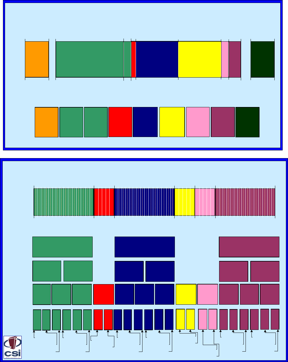
Band Plans
PCS Frequency Band Plan
Uplink In MHz
Downlink In
MHz
1850
1930
1865 1870 1885 1890 1895 1910
1945 1950 1965 1970 1975 1990
A Full
A1
A2
A3 A4 A5 D Full
B Full
B1B2
B3 B4 B5 E Full F Full
C Full
C1C2
C3 C4 C5
C6 C7 C9
UL 1850-1865
DL 1930-1945
UL 1865-1870
DL 1945-1950
UL 1870-1885
DL 1950-1965
UL 1885-1890
DL 1965-1970
UL 1890-1895
DL 1970-1975
UL 1895-1910
DL 1975-1990
UL 1895-1902.5
DL 1975-1982.5
UL 1902.5-1910
DL 1982.5-1990
UL 1895-1900
DL 1975-1980
UL 1900-1905
DL 1980-1985
UL 1905-1910
DL 1985-1990
UL 1895-1897.5
DL 1975-1977.5
UL 1897.5-1900
DL 1977.5-1980
UL 1900-1902.5
DL 1980-1982.5
UL 1902.5-1905
DL 1982.5-1985
C8
UL 1870-1877.5
DL 1950-1957.5
UL 1877.5-1885
DL 1957.5-1965
UL 1850-1857.5
DL 1930-1937.5
UL 1857.5-1865
DL 1937.5-1945
UL 1870-1875
DL 1950-1955
UL 1875-1880
DL 1955-1960
UL 1880-1885
DL 1960-1965
UL 1850-1855
DL 1930-1935
UL 1855-1860
DL 1935-1940
UL 1860-1865
DL 1940-1945
C11
C10
B6 B7 B9
B8 B11
B10
A6 A7 A9
A8 A11
A10 D1
D2 E1
E2 F1
F2
UL 1905-1907.5
DL 1985-1987.5
UL 1907.5-1910
DL 1987.5-1990
UL 1870-1872.5
DL 1950-1952.5
UL 1872.5-1875
DL 1952.5-1955
UL 1875-1877.5
DL 1955-1957.5
UL 1877.5-1880
DL 1957.5-1960
UL 1880-1882.5
DL 1960-1962.5
UL 1882.5-1885
DL 1962.5-1965
UL 1850-1852.5
DL 1930-1932.5
UL 1852.5-1855
DL 1932.5-1935
UL 1855-1857.5
DL 1935-1937.5
UL 1857.5-1860
DL 1937.5-1940
UL 1860-1862.5
DL 1940-1942.5
UL 1862.5-1865
DL 1942.5-1945
UL 1885-1887.5
DL 1965-1967.5
UL 1887.5-1890
DL 1967.5-1970
UL 1890-1892.5
DL 1970-1972.5
UL 1892.5-1895
DL 1972.5-1975
UL 1865-1867.5
DL 1945-1947.5
UL 1867.5-1870
DL 1947.5-1950
Cellular Frequency Band Plan
824
Uplink
(MHz)
Downlink
(MHz) 869
825
870
835
880
845
890
846.5
891.5
849
894
B’A’
B
A
A”
UL 825-835
DL 870-880
UL 824-825
DL 869-870
UL 835-845
DL 880-890
UL 845-846.5
DL 890-891.5
UL 846.5-849
DL 891.5-894
806 821
851 866
SMR 800
iDEN
UL 806-821
DL 851-866
SM800
UL 821-824
DL 866-869
SMR 900
UL 896-901
DL 935-940
896 901
935 940
794 806
764 776
Public
Safety
UL 794-806
DL 764-776
-6 -
Note: All frequencies are shown in MHz
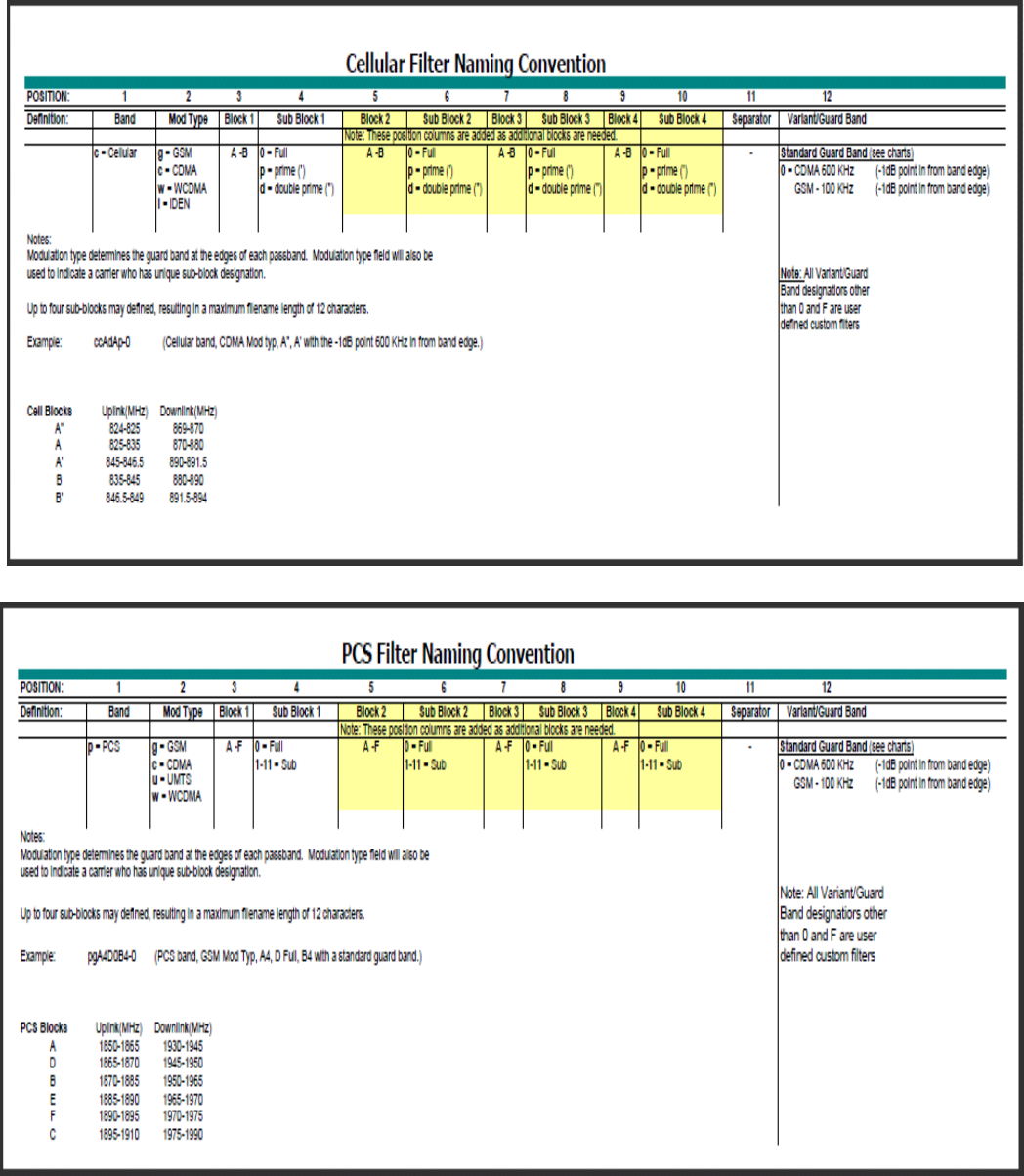
File Naming Conventions
- 7-
Note: Filter file names will be from six to twelve characters long. Each character position in the filter file name is
used to define the characteristics of the filter as shown above. All frequencies are shown in MHz

- 8 -
Functional Overview
CSI digital repeaters incorporates the following features for convenient operation, access,
protection, and control.
•Network Configuration and Control using either a webpage style GUI through
any standard browser or a menu driven user interface using the serial port.
Note: GUI does not require Internet access.
•User Gain Control (affects all passbands)
•Automatic Gain Control
•Automatic Power Control
•Oscillation Protection
•Over Drive Protection (P.A. limiting)
•Under/Over Voltage Protection
•Fault Protection
•Alarm Notification - Local/Remote
•Upgrade Support - Local/Remote
•External Interfaces - USB/Ethernet/Serial
•Re-loadable filters - Local/Remote
•Web-based monitoring and control - Local/Remote
•Persistent Status and Error information
LED Indicator
Automatic safety precautions are built into the amplifier system. In the case of a catastrophic system
event, a shutdown circuit is incorporated that will disable all emissions should the uplink input or downlink
input be over driven or should an oscillation or output overpower event occur. The amplifier will periodi-
cally attempt to recover from the detected condition automatically. Warning light indicators are as follows:
*Note: During Power up, the repeater will require a approximately three minutes for
the internal computer to boot up. During this time the LED on the front panel may light
and go out several times.
Do not unplug the unit while it is in the boot up process!
When a boot up is complete and no alarm conditions exist, the LED indicator will be illuminated green.
Should a fault condition develop the LED will illuminate red and the user may check the status page
of the GUI for the nature of the fault.*
- 9 -
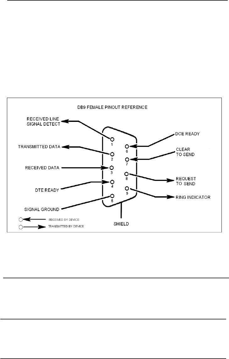
EIA232 Pin Specifications
USB Interface
The Universal Serial Bus (USB) interface conforms to Intel’s Universal Host Controller
Interface (UHCI) version 1.1 dated March 21, 1996. This interface will support data
transfer rates up to 12 Mbps and can be used for software updates and filter file
uploads.
Ethernet
The Ethernet AUI conforms to IEEE 802.3 and is capable of supporting 10/100 Mbps
communications speeds. This port is used to provide access to the GUI.
Monitoring & Alarms
There are no physical connections provided to specifically communicate system or alarm
status. This information is embedded in the information accessible via the communication
ports described earlier.
The diagram above is for reference only, it’s intended to provide a quick source for pinout
information in the event it should be necessary to adapt your serial cable because of an
unusual connector configuration. In the vast majority of cases this information will not be
needed.
Local Communication Interface Ports
To allow monitoring and control, the repeater is equipped with four ports that provide external
communication access (1 Ethernet CAT-5, 2 DB-9 serial, and 1 USB). The Ethernet, CAT-5 port
is provided as a primary communications port to the PC. One serial interface provides commu-
nications to local PC and the second to an external modem when provided. The USB interface
provides a means to download files from a memory device and may also be used by an
external modem. The DB-9 pin assignments conform to the standard Electronic Industries
Association (EIA232) specification. A diagram of the pin descriptions is provided on this page
for reference.
Connecting a null modem cable to one of the COM ports and using a terminal emulation
program with a PC will allow communication to the control processor’s Text Menu Interface
(TMI). See command line interface section for further detail.
System Set-Up Considerations
All cables should be checked for shorts and opens. Also verify that there are no cables with loose or poor connec-
tions. RF leakage could cause oscillation to occur under some conditions.
The rooftop antenna (Donor Antenna), if directional, should be checked for proper alignment along the calculated
compass heading. Typically, the directional antenna would be aimed at the same site that your handset uses, but it
may not always be so. It is critical the installer contact the service provider for information on, and
approval of the cell site he or she has selected before the system is turned on.
If cables and alignment are acceptable and a problem persists, it may be necessary to use a spectrum analyzer to
examine the signal environment in which the repeater is operating. The existence of strong adjacent channel
signals within the frequency band(s) can cause the AGC to reduce the amplifier’s gain or cause alarms. In some
cases additional filtering or attenuation might be required to reject these unwanted signals. In some instances, the
donor antenna can be reoriented horizontally, to place the interference source in an antenna pattern “null”. There
also may be some cases where the interference from outside signals is so great that they cannot be filtered or
otherwise reduced or eliminated without expensive and possibly prohibitive measures. In these cases it may not be
practical to use the repeater for providing coverage to these sites.
Selection of external attenuators to be used in line with the Repeater Antenna
Port(s):
- 10 -
DONOR PORT
If a repeater is installed in an area with very strong desired and/or undesired signals, it is important to ensure that
the overall signal levels are optimized to be within the best operating range of the repeater. Additionally, de-
sensing of a nearby base station site must be avoided. These goals can be accomplished by properly attenuating
the antenna port(s) in the path of the donor antenna(s). In effect, one can imagine that the particular repeater
deployment is electrically moved farther from the base station using attenuators that are equivalent to increasing
the path loss from the donor antenna to the base station.
The following potential outcomes result from the use of attenuators on the donor port(s) of the repeater: Uplink
output power, as reported by the unit, is reduced by the value of the attenuation, protecting nearby base stations.
Downlink signal to noise ratio is high at the point of the attenuator, resulting in slight but negligible reduction in
downlink performance. Other performance is essentially unchanged.
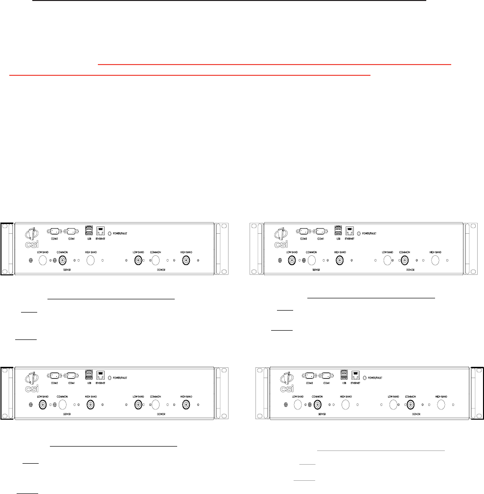
Input: Two single band duplex ports, one from the cell donor
and one from the PCS donor.
Output: One dual band duplex port to the DAS.
2:1 PORT CONFIGURATION 1:2 PORT CONFIGURATION
Input: One dual band duplex port from the dual band donor.
Output: Two single band duplex ports one to the Cellular DAS and
one to the PCS DAS.
2:2 PORT CONFIGURATION
Input: Two single band duplex ports, one from the cell donor and
one from the PCS donor.
Output: Two single band duplex ports one to the Cellular DAS and
one to the PCS DAS.
Input: One dual band duplex port, from the dual band donor.
Output: One dual band duplex port to the DAS.
1:1 PORT CONFIGURATION

-11 -
SERVER PORT
Server port attenuation may also be necessary, particularly where a powered DAS is present. The selection guidelines
below apply to both server and donor ports. In order to properly measure uplink signal strength, a signal generator
should be used. If a signal generator is not available, placing a test call while under the server antenna with the least
path loss to the repeater should provide reasonable data.
The following potential outcomes result from the use of attenuators on the server port(s) of the repeater: Downlink
output power, as reported by the unit, is reduced by the value of the attenuation. Uplink incoming power from the DAS
is reduced, along with potentially strong and/or harmful out-of-band signals (including noise) that are generated by the
DAS.
Attenuator Selection Guidelines:
Accurate attenuator values need to be chosen to ensure that the maximum total power (higher of Composite or In-
Band Input) applied to the donor and server port(s) does not exceed the following thresholds:
Input Signal Max Gain Input Signal Max Gain
<-45 dBm 85 dB -32.2 dBm 69 dB
-44.3 dBm 84 dB -31.4 dBm 68 dB
-43.6 dBm 83 dB -30.6 dBm 67 dB
-42.9 dBm 82 dB -29.8 dBm 66 dB
-42.2 dBm 81 dB -29 dBm 65 dB
-41.5 dBm 80 dB -28.2 dBm 64 dB
-40.6 dBm 79 dB -27.4 dBm 63 dB
-39.7 dBm 78 dB -26.6 dBm 62 dB
-38.8 dBm 77 dB -25.8 dBm 61 dB
-37.9 dBm 76 dB -25 dBm 60 dB
-37 dBm 75 dB -24.4 dBm 59 dB*
-36.2 dBm 74 dB -23.8 dBm 58 dB*
-35.4 dBm 73 dB -23.2 dBm 57 dB*
-34.6 dBm 72 dB -22.6 dBm 56 dB*
-33.8 dBm 71 dB -22 dBm < 55 dB*
-33 dBm 70 dB
*We recommend padding this level due to potential for fluctuating signal.
-25 dBm is the maximum input signal level that should be applied to the repeater, even if the gain is lower than 55 dB.
Input signals exceeding these thresholds will result in composite input attenuation, called “ADC Protect” (Analog to Digital
Converter Protection). Output power is reduced whenever the above thresholds are exceeded by reducing the gain by 1dB for
each 1 dB that the threshold is exceeded. ADC Protect should not be confused with AGC (Automatic Gain Control), which
reduces gain to prevent In-Band (measured) output power from exceeding the specified maximum output level.
To determine the total power applied to the donor and server ports, please reference the “Composite Input” values as reported in
the Web (“System Status”) or Menu (“Link Status”) interfaces (depicted and explained later in this manual).
Large delta’s between in-band and composite input signals:
Care should be taken to isolate the best donor site to ensure the least possible delta between in-band and composite downlink
signals.
If the (downlink) composite input exceeds the in-band input by more than 3 dB Cellular, or more than 5 dB PCS, the maximum
output power will be reduced. Example:
Band 1 (Cellular)
In-Band Input -45 dBm
Composite Input -33 dBm
Max Gain = 70 dB
Max Output = 25 dBm
-12-
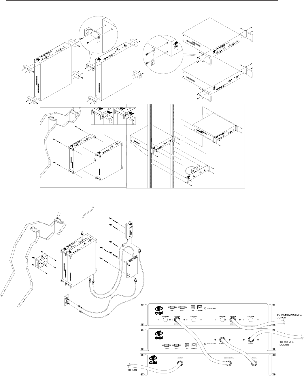
Mounting the Digital Repeater
The following diagrams illustrates the methods for mounting the repeater(s) in a typical wall or rack installation.
Brackets are provided for both options.
Rack mount of the repeaters requires just two brackets mounted to the front corners of each module. Note: the CSI digital repeaters
must be supported in the rack system with a shelf or slide rail. Do not rely on the brackets exclusively to support all the
weight of the modules.
Mount the Cross Band Coupler on the wall close enough
to the repeater modules to allow the RF jumpers to reach
from the CBC to the repeaters. The attachment system
used to anchor the CBC to the wall must be able to
support at lease 4.2 lbs / 1.9 kg.
The wall anchoring system you use for the repeaters
will need to be able to support at lease 19.6 lbs/ 8.9 kg
for each dual band module and 11.6 lbs/ 5.3 kg for
each single band add on module. The power supplies
are mounted approxamately as shown.
Interconnection of the repeaters in the rack mount configuration
requires the short RF Jumpers supplied with the CBC Module.
One will connect from the server port of the dual band module to
the 800MHz/1900MHz port on the CBC module. The other will
connect from the server port on the single band module to the
700MHz port on the CBC module.
Wall mount interconnection requires one connection
from the server port of the dual band module to the port
labeled “High” on the Cross Band Coupler. The other will
connect from the server port on the single band module
to the port labeled “Low” on the CBC.

- 13 -
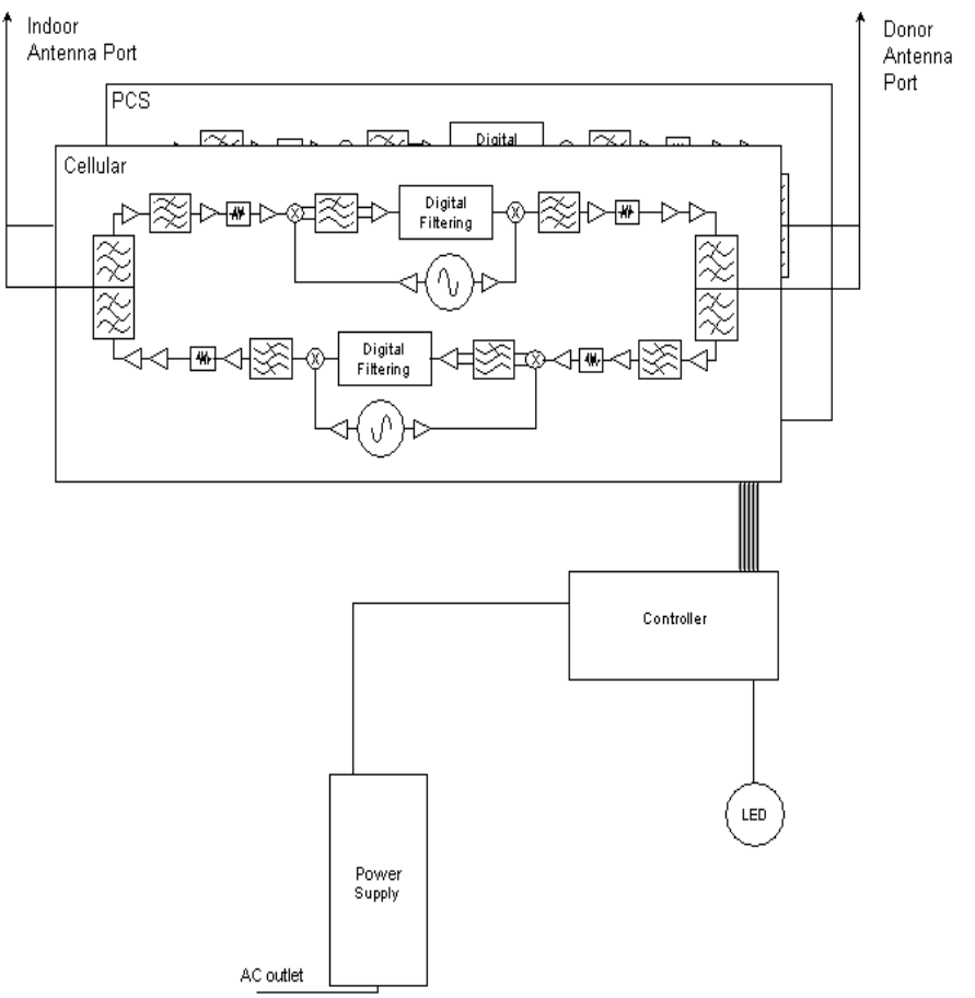
Circuit Operational Description
The repeater uses a single down-conversion/up-conversion scheme. There are multiple RF amplifier
stages prior to each down-converting mixer. The down-converting mixers are followed by a single IF
amplifier. A Digital Signal Processor block then processes the resultant digitized IF signal that was
previously generated by an Analog-to-Digital Converter. The processed (filtered) digital signal is fed to a
Digital-to-Analog converter and then up-converted to RF. A driver amplifier and a final power amplifier
make up the final gain stages before application to the diplexer. The maximum total system gain (diplexer
input to diplexer output) is nominally 85 dB for either the downlink or the uplink paths with both links
having independent manual and automatic gain controls (AGC).
AGC reacts to analog power detection on both the input and output of the uplink and downlink RF
chains. A control algorithm continuously monitors these detected values and dynamically adjusts
various gain stages such that the net system gain value, entered manually, is optimally maintained
without either exceeding FCC parameters or over driving the A/D converters.
An LED on the front panel provide immediate visual indication of the unit’s primary power alarm
status. The repeater features automatic shutdown protection as a safety measure should
excessive drive be applied to the input or an oscillation condition occur. When in a protected mode,
a control algorithm determines the appropriate method of recovery to a normal, previously defined
state, or maintains the protection until manually reset. If recovery has been established, the LED will
be illuminated green or available to be reset. The events that trigger the error will be saved in the
event log.
Optional Accessories
A complete line of accessories is available from Cellular Specialties, Inc. Check with your CSI distributor
for any additional items needed. Below are just a few examples suitable for most in-building needs.
•Outside Donor Antenna •UPS
PCS - model number: CSI-AY/1.85-1.99/10 Battery backup, 2 hr Single band
Cellular - model number: CSI-AY/806-960/14 1 hour dual band - model number: CS48-985-600
•Inside Omnidirectional Antenna
Quad-band - model number: CSI-AO/700/2.7K/3 Battery backup, 4 hr Single band
•Power Dividers 2 hour dual band - model number: CS48-985-601
2:1 - model number: CSI-SPD2/700-2.5K/N
3:1 - model number: CSI-SPD3/700-2.5K/N
4:1 - model number: CSI-SPD4/700-2.5K/N
•Grounding Kit - model number: CSI-GKIT
•Lightning Arrestor - model number: CSI-CAP
•Directional Couplers
6dB - model number: CSI-DC6/700-2K/N
10dB - model number: CSI-DC10/700-2K/N
15dB - model number: CSI-DC15/700-2K/N
20dB - model number: CSI-DC20/700-2K/N
30dB - model number: CSI-DC30/700-2K/N
Important Installation Notes
•Inadequate isolation between the outside and inside antennas may cause regenerative
feedback in the system. This feedback can cause the amplifier to emit a continuous signal at
maximum amplitude and, in some cases, interfere with normal operation of the cell site. Careful
consideration of the layout and placement of the system is imperative.
•The installer should refer to the Safety Guidelines section on page 4 and the Important Safety
Information section on page 5 for proper antenna selection and installation. To avoid serious injury
or death and damage to the repeater, do not install donor or server antennas near overhead
power lines or high power components. Allow enough distance so that if antennas should fall
they will not come in contact with those components.
••
••
•Close proximity to the donor or server antennas with the repeater in operation may expose
the user or installer to RF fields that exceed FCC limits for human exposure.
WARNING! AMPLIFIER OR HANDSET DAMAGE MAY OCCUR IF A HANDSET IS CONNECTED
DIRECTLY TO THE REPEATER OR THE COAX THAT LEADS TO THE REPEATER.
•Cross Band Couplers
Quad band Rack Mount: CSI-CM250-7/C/AW/P
(700 LTE, Cell, AWS and PCS)
Quad band Wall Mount: CSI-CBC/696-2170/N
(700 LTE, Cell, AWS and PCS)
Tri band Rack Mount: CSI-CM250-U7C/C/P
(700 Upper C LTE, Cell and PCS)
Tri band Wall Mount: CSI-CBC21/740-1990/N
(700 Upper C LTE, Cell and PCS)
Tri band Rack Mount: CSI-CM250-L7AB/C/P
(700 Lower A/B LTE, Cell and PCS)
Tri band Wall Mount: CSI-CBC21/696-1990/N
(700 Lower A/B LTE, Cell and PCS)
-14 -
Functional Block Diagram
- 15 -
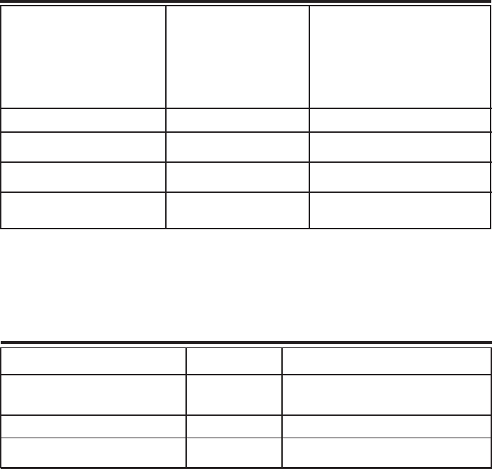
Color Satin Black
Parameter Specification Notes
AC Voltage 100 - 240 VAC External Power Supply
AC Power Frequency 47 - 63 Hz
Weight 19.6 lbs / 8.9 kg
Thermal Management Fan Cooled
Surface Coating Powder Coat
AC Current 3.2 Amps @ 120 VAC
1.7 Amps @ 230 VAC
Parameter Specification Notes
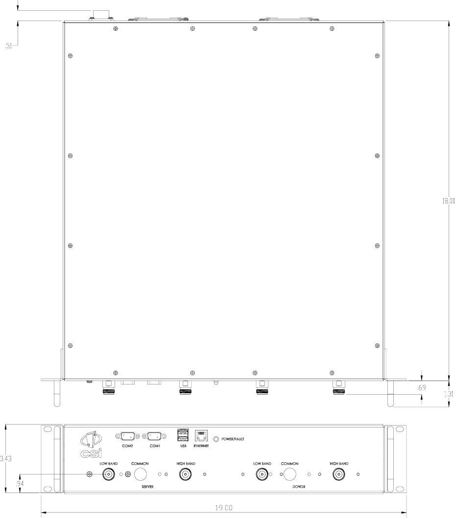
Repeater Size
Height 3.43 in.
Width 19.00 in.
Depth 18.00 in.
Heat Output 1000 BTU/Hr
Mechanical Specifications
AC Power Specifications

-16 -
OIP3 Measured with 2 CW tones at 14
dBm/tone
Linear Output Power + 27dBm max Uplink and Downlink
(CSI-DSP85-250-C/P & CSI-DSP85I-250-C/P) CELL +26dBm ** **AGC Set Point
PCS +25dBm **
(CSI-DSP85-251-C/P& CSI-DSP85I-251-C/P) + 30dBm max
Noise Figure (Avg) 6.0 dB At Maximum Gain
Parameter Specification Notes
Maximum RF input Power +10 dBm
without damage
Linear Gain 85 dB Factory Calibrated Gain
Pass Band Ripple +/-1.5 dB
Automatic Gain Control (AGC) 30 dB max In 0.5 dB steps
range
Manual Gain Control 53.5-85 dB In 0.5 dB steps
RMS Vector Error (EVM) 3% max TDMA,EDGE,W-CDMA,CDMA2000
CDMA RHO 0.98 min CDMA2000, 1x-EVD0
Spurious Emissions &
Applicable Documents
FCC -13 dBm max Per FCC part 2, 22, 24
Industry Canada -13 dBm max
Propagation Delay <2.5 usec
Input VSWR (Typ) <1.5:1
+ 41 dBm
Environmental Requirements
Parameter Specification Notes
Relative Humidity 5% to 95% Non-condensing
Industrial Dust <15mg/m3 Telcordia GR-63-CORE
Temperature Range -30 to +48 C
(-22 to +118 F)
00
00
1dB Compression Uplink and Downlink
+ 31 dBm
Connectors N-Female 2 -4 Depending on configuration
Dual Band Operating Power Parameters
CELL +29dBm **
PCS +28dBm **
- 17 -
Mechanical Drawing
-18 -
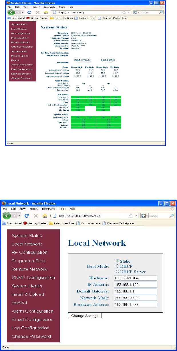
When login is complete the user is brought to the system status page. The links on the page are
activated by clicking on them.
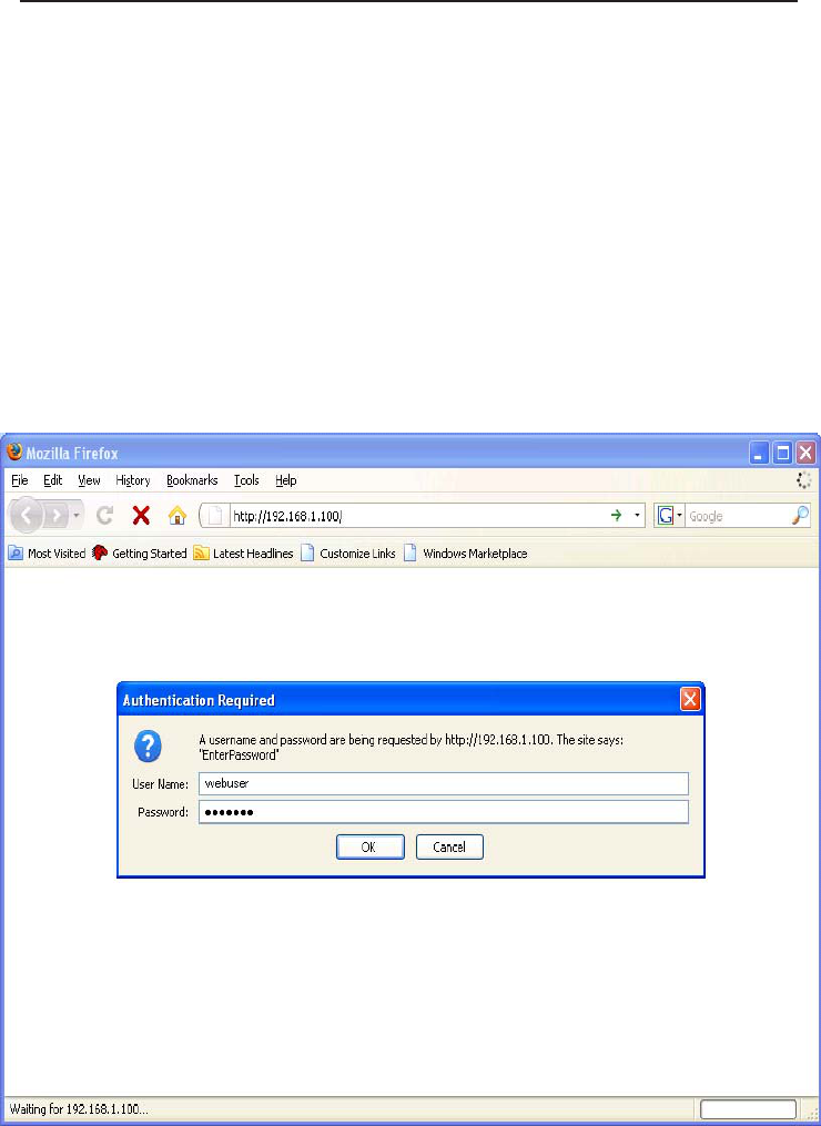
Web based GUI Session
Primary access to the repeater is gained using a LAN connection and a web browser program
such as Firefox by Mozilla, or Internet Explorer from Microsoft. The repeater ships with the
default IP address of 192.168.1.100, but it can be changed later if required.
If connecting directly to the repeater from a laptop or PC with a crossover CAT-5E cable or
over a LAN the user types the IP address of the repeater into the browser address line to
connect. (Note: Most users will need to update the TCP/IP settings on their computer to enable
connection to a host that has a static IP. Select “Use the following IP Address” and enter the IP
Address as follows: 192.168.1.x, where “x” = any number from 2 to 254 inclusive other than
100. The subnet mask is 255.255.255.0. Questions pertaining to these settings should be
referred to the user’s IT department or you may refer to the Additional Tips section at the end
of this manual.) When connection is made the user will be prompted for a user name and
password. For the purpose of the GUI session, the default user name is webuser and the
password is csi1234. This can also be changed as required. Internet access is not required
to use the GUI. (Note: If you are connecting using a laptop, verify that your Ethernet port is
powered. Some laptops will not allow Ethernet connection when on battery power. If this is
the case with the laptop you are using you will need to plug it in or update the power settings.)
System Status:
-19 -
If the user selects Local Network from the System Status page, the following screen is displayed
and from here network configuration can be modified as required. The default is set to Static. Check
with your IT department for explanation and approval of the DHCP and DHCP Server options you
plan to use before you select them. *NOTE: In units with software version 2.2.4 or prior, only
letters, numbers and underscores are acceptable nomenclature. In units with software version
2.3.0 and up, Underscores are not acceptable; however, hyphens are acceptable.
After changes are made, press the refresh button to review the fields and ensure the
change made is correct. Note: changing network settings will cause the current TCP/IP connec-
tion to fail because change will take effect immediately. From here the user may return to the
System Status screen or click on the other options.
Local Network:
- 20 -
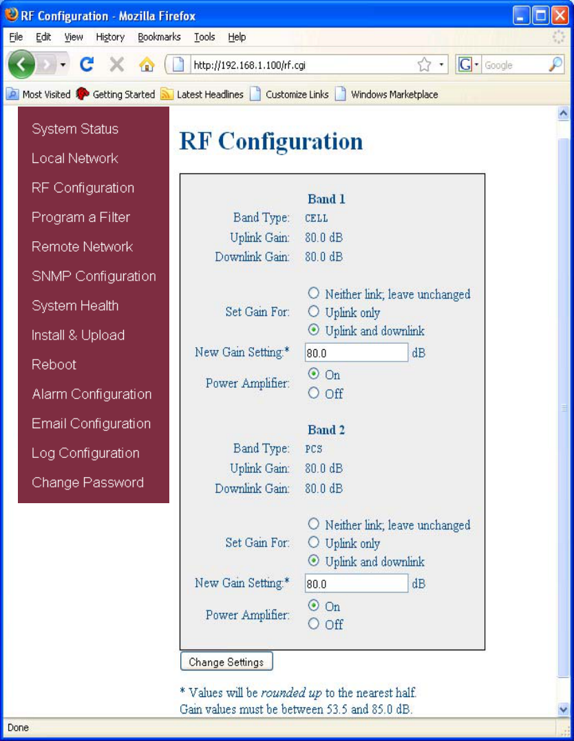
If the user would like to modify RF configuration, click on the words RF Configuration in the
navigation box and the screen below is displayed.
To change gain settings the user will select the Uplink only or Uplink and downlink radio buttons.
The user then inputs the gain value desired. Gain values from 53.5 dB to 85.0 dB may be selected.
The repeater will not allow values outside this range. By pressing the Change Settings button the
gain change is implemented.
RF Configuration:
- 21 -
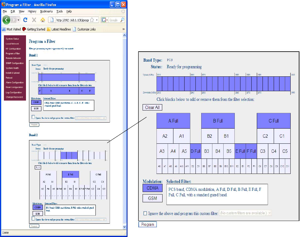
When a new filter set is required, it may be selected by clicking Program a Filter in the navigation
box. The user may select the desired filter by pressing the band/sub-band and modulation
selection buttons. Undesired bands/sub-bands, if lit, will require the user to manually “deselect”
them before programming. To aid the user a clear all button is provided on the PCS band and will
deselect all band and sub-bands simultaneously. Pressing the Program button will complete the
selection and load the desired filter. The time required to complete this process will take just a
few moments. Note: If the filter desired is not currently in the unit, additional filters along with
instructions on how to load them, are available by contacting CSI.
Program a Filter:
- 22 -
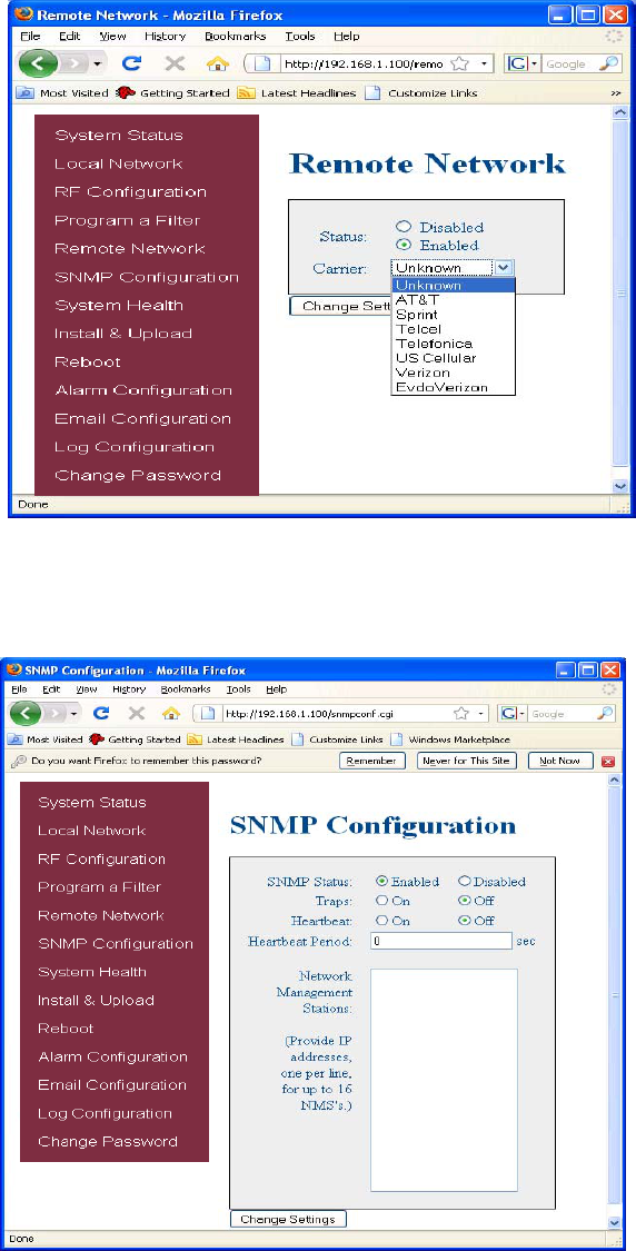
To change SNMP settings click SNMP Configuration in the navigation box, the screen below
will be displayed. If the user is not well versed in Simple Network Management Protocol he or
she should check with their IT professional for proper setting requirements.
Remote Network:
SNMP Configuration:
If the repeater includes a USB modem kit, click on Remote Network in the navigation box and the
screen below is displayed. Highlight the carrier on whose network the repeater and modem will be
configured and click the Change Settings button. Refer to the documentation included with the modem
kit for addtional information on configuring the modem. If the repeater is connected to an ethernet
device for remote access and/or monitoring, this feature must be disabled.
- 23 -
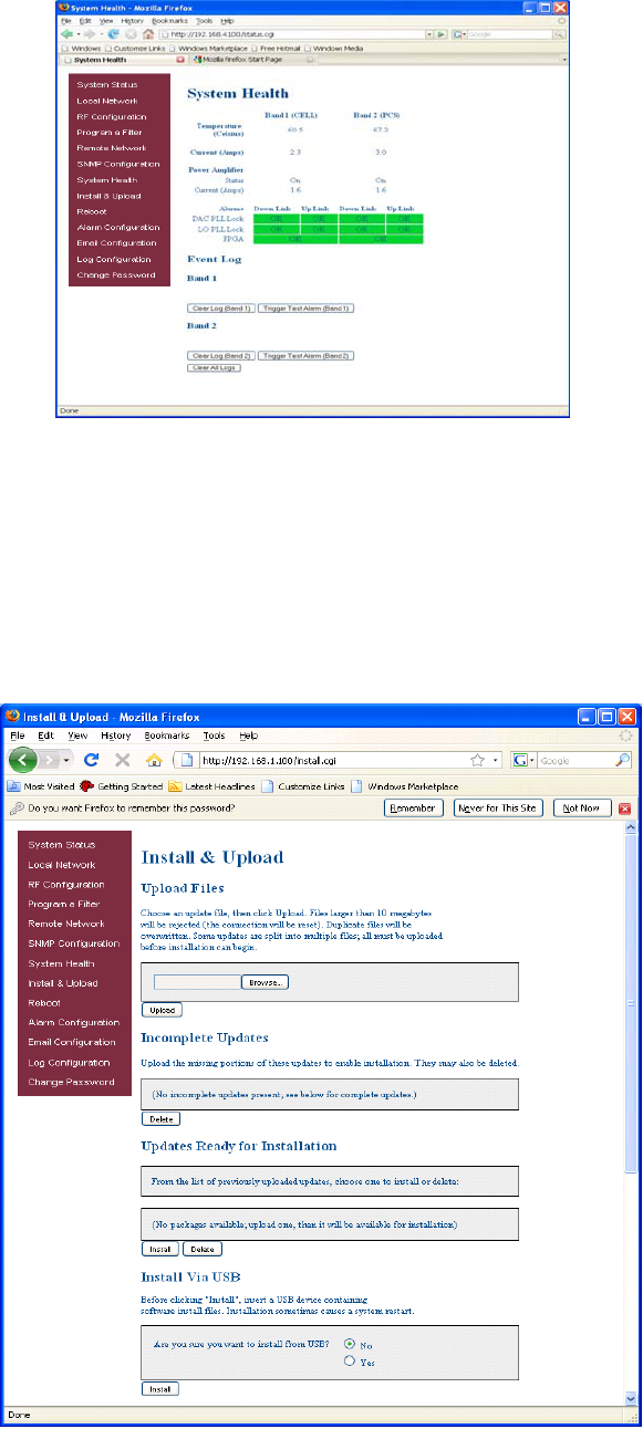
By clicking System Health the current state of the repeater can be reviewed.
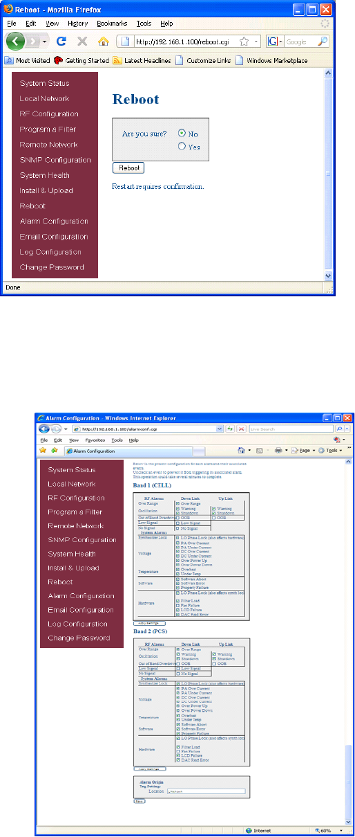
Should a software install or upgrade be needed it can be done from the Install & Upload screen
shown below. As with the other screens it can be reached by clicking the words in the naviga-
tion box. Contact CSI for updates and instructions.
***The user may clear LED indicators, alarms and the Event Log by clicking the Clear Log button.
***
System Health:
Install & Upload:
**** If required in your market, visit the “System Health” screen and click on “Trigger Test Alarm”
and wait for confirmation that the Wireless Service Provider representative that is responsible
for monitoring the repeater has been notified of the alarm. Be sure to “Clear All Logs” prior to
logging out of the Web Interface.
****
- 24 -
Alarm Configuration:
The Alarm Configuration page allows the user to specify what events will trigger an alarm.
*NOTE: Letters, numbers & hyphens are the only acceptable nomenclature for the Location field and hyphens may not be
used as the first or last character.
If a reboot of the repeater becomes necessary click on the Reboot option in the navigation box
and the Reboot page is displayed. Note: a reboot will take 3-5 minutes to complete.
Reboot:
-25 -
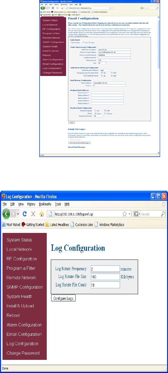
Email Configuration:
The Log Configuration page provides the user with the means to change three aspects of how
log files are created and stored as shown below.
Log Configuration:
Email Configuration page allows the user to enter up to five Email addresses to which the repeater can send
specified alarm messages when the repeater is connected via ethernet or wireless modem and Email Alarm
Notification or Remote Networking are enabled. *NOTE: In all fields the software will not allow the user to enter
invalid characters.
- 26 -
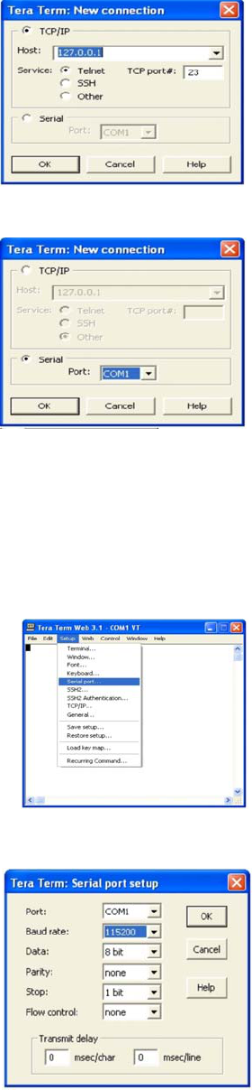
Text Menu Interface (Local Access)
Local access to the repeater TMI, also known as the console interface, is made by connecting a serial
cable (optional), as shown in Figure 1, from the serial connector of the laptop to either of the serial ports on
the repeater. These connectors are labeled COM 1 and COM 2. In some cases, if the gender of the
connector is not the same as shown in figure 1, a null modem adapter (optional) as shown in Figure 2 may
also be required.
Figure 1 Figure 2
To end the session exit the browser, the user will be automatically logged out.
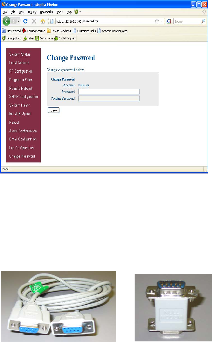
By clicking on the Change Password link the user is brought to the Change Password page. From here he or she can
quickly and easily reset the password for the unit. A word of warning here be careful when setting the new password. If
you forget what you set your password to you’ll need to contact CSI at 1-877-844-4274 for assistance.
Change Password:
-27 -
Many terminal emulation programs will work if properly configured. In the following description,
“TeraTerm” is used to establish the TMI session. This program is readily available via the Internet
and is free from Ayera Technologies at: http://www.ayera.com/teraterm/
TeraTerm Pro Web works on Windows 95/98, 2000, XP. Here is the latest TeraTerm Pro Web
release: Version 3.1.3, October 8, 2002. ttpro313.zip
When the program is started, the following screen is displayed.
Select the Serial radio button and press OK as shown below.
Note: It may be necessary, in the System Properties section of the control panel; using Device
Manager to determine what COM port your computer uses for the communications port. In this case
it is COM 1. This is not to be confused with the serial port on the bottom panel of the unit labeled
COM 1.
Pressing “OK” will open up a blank dialog screen. Go to the setup dropdown menu and
select “Serial port” to make changes to the serial port setup.
Configure the terminal program for the correct COM port, in this case COM 1 and 115200
baud rate as shown below.
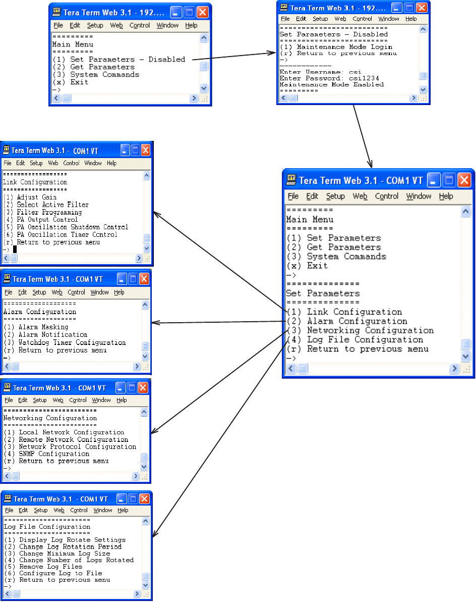
After completing the serial port changes (pressing the enter key will be required to complete
the action) the user will be prompted for a user name and password. In dual band units each
band is changed independently and requires an independent login. To make changes to the
cellular band, the default user name is “cellband”. The user name for changing the PCS band
is “pcsband”. The password for both bands is “csi1234”. After entering the password and
pressing return the TMI main menu will appear. Note: by default the Set Parameters option is
disabled. To re-enable the user will press 1 and will be prompted for a username and pass-
word. The default user name is csi and the password is csi1234.
The actions displayed
are self-explanatory.
Pressing “1” will
continue to expand this
session screen and
allow the following
parameters to be set.
- 28 -
-29 -
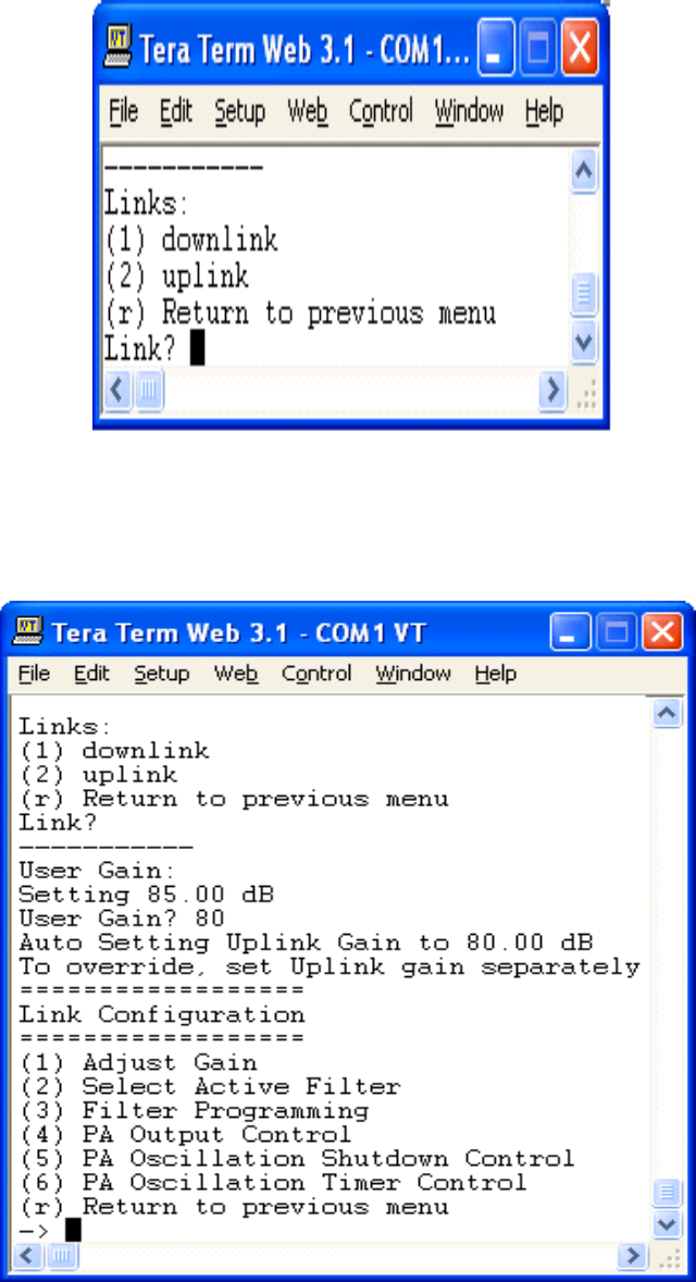
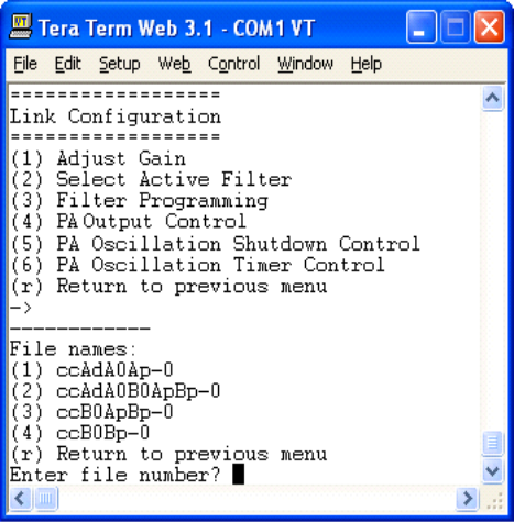
Each “Set Parameter” selection, when chosen will be expanded to allow changing or setting of that
parameter. For example from the Link Configuration menu on the previous page, selecting 1 - Adjust
Gain will display the menu shown below.
After selecting option 1, downlink, the current user gain is displayed and the option to change it
is accomplished by typing the desired gain at the prompt. The user is then returned to the
previous menu.
-30 -
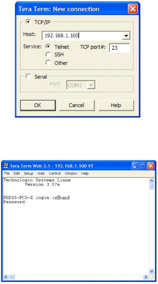
All the other options operate in much the same way. Some of the options will offer the user
additional selections and will be self-explanatory. Below is one example of these additional options,
the one shown below is the result of selecting (3) Filter Programming.
Note: Graceful session termination is important. Use Disconnect under the file dropdown menu
to terminate a session, otherwise the port may become disabled and force the system to be
rebooted.
Telnet Session (Remote Access)
Remote access to the repeater may be gained through a LAN connection and a terminal emula-
tion program for TCP/IP. As with the serial connection, many terminal emulation programs will
work, if properly configured. In the following description, “TeraTerm” is used to establish the
Telnet session. Also, it will be required that the network configuration of the computer and the
repeater being controlled be set up with the same Sub Net and Sub Net Mask in order to establish
a link. In other words, the IP addresses of both the computer used and the repeater must use the
same group of IP address number sets. For example, the repeater ships with the default IP
address of 192.168.1.100 and a Sub Net Mask of 255.255.255.0. In order to connect, the
computer to be used for the link would normally need an IP address of something like
192.168.1.12 with a Sub Net Mask of 255.255.255.0, the same Sub Net Mask as the repeater. In
this example note: the last digit of the IP address may be any number except 1,100 and 255.
Configuring your PC is normally fairly straight forward but it does vary somewhat with the
operating system involved. If you require assistance, contact your IT department and they will
be able to set up your PC for you or you may review the Additional Tips Section at the end of the
manual.
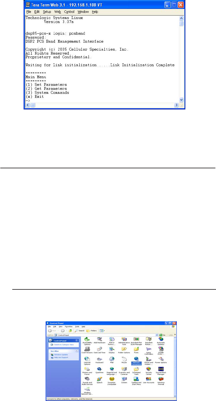
When the TeraTerm program is started, the following screen is displayed. Change the default
host IP address to the IP address of the repeater to be controlled. In the case of a new install, the
default address is 192.168.1.100 and has been assigned at the factory. Select the service Telnet.
The TCP Port must be 23.
-31 -
Pressing the “OK” button will bring the user to the following screen, which will require the user
to log in. In dual band units, each band is changed independently and requires an independent
login. To make changes to the cellular band the default user name is “cellband”. The default
user name for changing the PCS band is “pcsband”.
In the field after the prompt type the user name for the band to be changed. The default password
is “csi1234” for both bands. After typing the password press the enter key and the main menu
will be displayed as shown next.
- 32 -
Telnet and serial sessions both provide access to the same Text Menu Interface. This
manual has already discussed many of the options available, those as well as the
options not covered are self explanatory, so they will not be repeated in the Modem
Interface section.
Modem Interface (Remote Access with login)
A modem can also be used to gain remote access to the unit provided the repeater has been
properly equipped. A selection of modems is available as an option. If the modem requires a SIM
card for activation, special requirements must be met for the SIM card to become fully functional,
contact the service provider. In addition, an IP address must be obtained and entered into the
repeater.
Once the modem has been installed and activated, it can be accessed from any terminal emulation
program just as in the serial and Telnet examples provided earlier. Access response time will
depend on many factors, some of which are:
•Quality of the connection (RF signal in the case of wireless modems)
•Technology (CDMA, EDGE, GPRS, etc.)
•Network congestion (Throughput)
When a connection has been established, the same login screen shown in both the serial and
Telnet examples is presented.
Additional Tips
Instructions to change TCP/IP settings on your Windows computer.
Click in the Network Connections Icon in the Control Panel. See below.
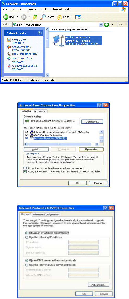
- 33 -
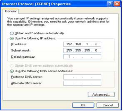
If you are set up to use DHCP, the window shown below will be displayed.
Select “Use the following IP address:” and enter “192.168.1.2.” The subnet mask should automatically
populate to “255.255.255.0.
Scroll down and highlight “Internet Protocol (TCP/IP) and click on the “Properties” button.
Right click on Local Area Connection - and select “Properties”.
- 34 -
Nothing else will need to be chosen or entered. Click “OK”, then “OK” again and retry connection.
A crossover Ethernet cable (supplied) must be used for Web Interface access. As a reminder, you must verify the
Ethernet port on your laptop is powered. If your laptop is on battery power, the Ethernet port may be inactive by
default. If this is the case simply plug in the laptop to a 110vac source or change the power settings to enable the
Ethernet port when the laptop in using battery power.
When troubleshooting RF issues, and when surveying challenging RF environments, it’s important to have a spectrum
analyzer capable of measuring the frequency that you are working with. An attenuator should be used to protect the input
when connected to a source of RF power such as the repeater or a powered DAS.
Both Uplink and Downlink should be measured. Downlink should be measured on the donor cable and at the output
(server) port of the powered up repeater, and Uplink at the lead from the DAS (on fiber/powered DAS’s, where the lead
would connect to the server port on the repeater) and at the donor port with the repeater powered up. Measurements
may also be necessary at server antenna locations. Your spectrum analyzer will need to be equipped with a whip
antenna for this.
Resolution Bandwidth (RBW) should be set at 200 kHz for GSM and 1 MHz for CDMA. If you cannot select these values,
the closest available values should be used. Video filter should be about one tenth of RBW. Other settings like span are
whatever is appropriate. One should also make sure that there are no signals above the top of the screen.
If you cannot see an adjacent out of band signal when using the 1 MHz RBW filter, you can decrease the RBW, to see
the close-in-frequency signals. Be sure to set the RBW back when you want to measure the power level.
RF Notes:
To prevent overload of the DSP input stages, the maximum measured level of in-band or out of band signals should be
less than -50 dBm when the DSP gain is set to 85 dB, -40 dBm when set to 75 dB, etc. This applies when there is one
dominant signal and applies TO BOTH THE DOWNLINK AND UPLINK. If there are two dominant signals, and the gain is set
to 85 dB, then the level of each signal should be kept to less than -53 dBm. With three signals, each should be less than
-55 dBm. With ten signals each should be less than -60 dBm. This latter reduction prevents the composite power of the
multiple signals from exceeding an acceptable level. Add fixed attenuators in line with the donor antenna line/DAS feed
to keep signals below the levels indicated above.
Suggested spectrum analyzer setting:

- 35 -
One Year Limited Warranty
Seller warrants that its products are transferred rightfully and with good title;
that its products are free from any lawful security interest or other lien or
encumbrance unknown to Buyer; and that for a period of one year from the
date of installation or fifteen months from the date of original shipment, which-
ever period expires first, such products will be free from defects in material and
workmanship which arise under proper and normal use and service. Buyer’s
exclusive remedy hereunder is limited to Seller’s correction (either at its plant
or at such other place as may be agreed upon between Seller and Buyer) of
such defects by repair or replacement at no cost to Buyer. Transportation costs
in connection with the return of products to Seller’s plant or designated facility
shall be paid by Buyer. The provisions of this warranty shall be applicable with
respect to any product which Seller replaces pursuant to it. SELLER MAKES
NO WARRANTY, EXPRESS OR IMPLIED, OTHER THAN AS SPECIFICALLY
STATED ABOVE. EXPRESSLY EXCLUDED ARE THE IMPLIED WARRANTIES
OF MERCHANTABILITY AND FITNESS FOR PURPOSE. THE FOREGOING
SHALL CONSTITUTE ALL OF SELLER’S LIABILITY (EXCEPT AS TO PATENT
INFRINGEMENT) WITH RESPECT TO THE PRODUCTS. IN NO EVENT
SHALL SELLER BE LIABLE FOR SPECIAL, CONSEQUENTIAL OR INCIDEN-
TAL DAMAGES, INSTALLATION COSTS, LOST REVENUE OR PROFITS, OR
ANY OTHER COSTS OF ANY NATURE AS A RESULT OF THE USE OF
PRODUCTS MANUFACTURED BY THE SELLER, WHETHER USED IN
ACCORDANCE WITH INSTRUCTIONS OR NOT. UNDER NO CIRCUM-
STANCES SHALL SELLER’S LIABILITY TO BUYER EXCEED THE ACTUAL
SALES PRICE OF THE PRODUCTS PROVIDED HEREUNDER. No represen-
tative is authorized to assume for Seller any other liability in connection with
the products.
Industry Certifications/Registration Numbers:
FCC: NVRCSI-DSP85-250-C/P, NVRCSI-DSP85-251-C/P IC: 4307A-DSP85-250-C/P, 4307A-DSP85-250-C/P
- 36 -
Index
A
AC Current 15
AC Power Frequency 15
AC Voltage 15
Additional Tips 32
AGC 5
Alarm Configuration 24
APC 5
Application 4
AUI 5
Automatic Gain Control 16
C
CDMA RHO 16
Change Password 26
Circuit Operational Description
13, 19, 22, 23, 24
Connectors 16
CPU 5
CSI 5
D
DAS 5
DHCP 5
DSP 5
E
EEPROM 5
EIA232 Pin Specifications 9
Email Configuration: 25
ERP 5
Ethernet 9
Event Log 23
F
FPGA 5
Functional Block Diagram 14
Functional Overview 8
H
Heat Output 15
I
Important Installation Notes 13
Important Safety Information 5, 13
Industrial Dust 16
Industry Certifications/Registration
Numbers 35
Input VSWR 16
Install & Upload 23
Install Software 23
L
LED 5
LED Indicators 8
Linear Gain 16
Linear Output Power 16
Local Communication Interface Ports
9
Local Network 19
Log Configuration 26
M
Manual Gain Control 16
Maximum RF input Power 16
Modem Interface 32
Modem Interface (Remote Access
with login) 32
Monitoring & Alarms 9
N
Noise Figure 16
O
OIP3 16
Optional Accessories 13
P
Pass Band Ripple 16
Power supply cable connectors 12
Product Introduction 5
Product Registration Information 4
Program a Filter 21
Propagation Delay 16
R
Reboot 24
Relative Humidity 16
Remote Network 22
Repeater Size 15
RF configuration 20
RF Notes 34
RMS Vector Error 16
S
Safety Guidelines 4
SBC 5
SNMP 5
SNMP Configuration 22
Spurious Emissions & Applicable
Documents 16
Suggested spectrum analyzer setting
34
Surface Coating 15
System Health 23
System Set-Up Considerations 10
System Status 19
T
Telnet Session 30
Telnet Session (Remote Access) 30
Temperature Range 16
Terms used in this manual 5
Text Menu Interface 26
Text Menu Interface (Local Access)
26
Thermal Management 15
TMI 5
U
UHCI 5
USB 5
USB Interface 9
W
Wall Mounting 12
Warranty 35
Web based GUI Session 18
Weight 15

- 37 -
Notes

- 38 -
Notes

- 39 -
Notes

960-1041-011 rev A ECO2356