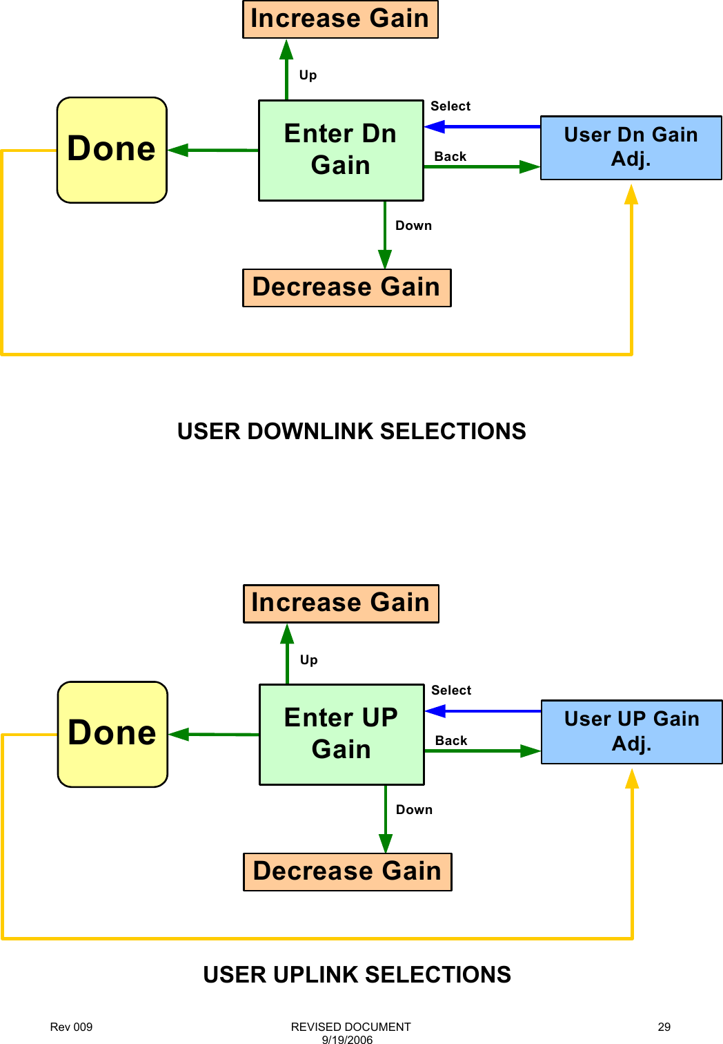
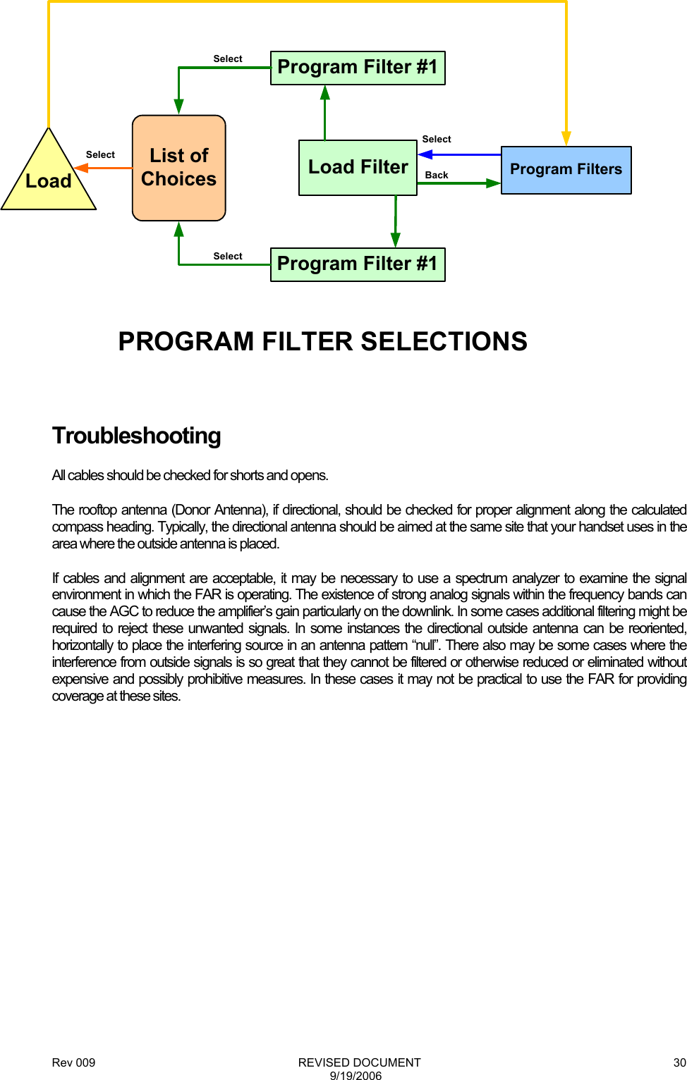
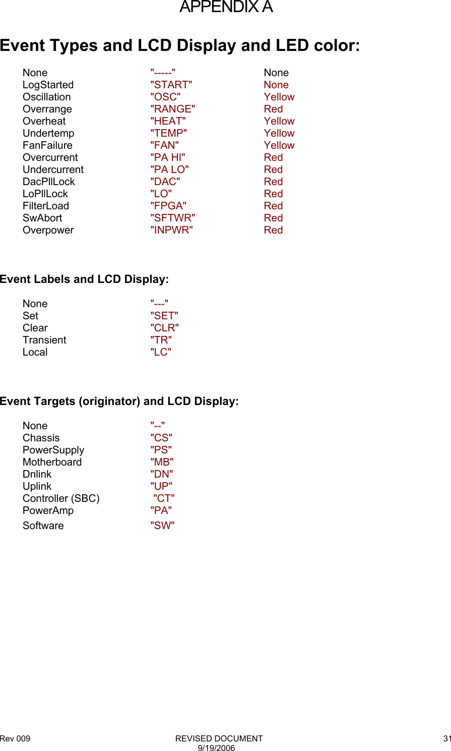
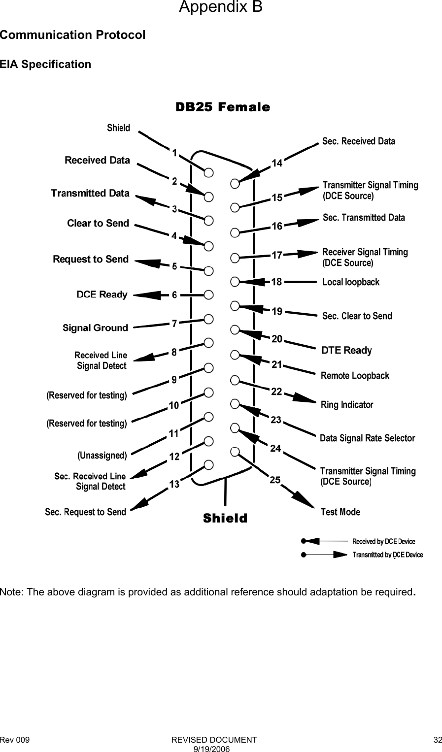
Westell CSI-DSP85-1W-C Digital Repeater User Manual Exhibit D Users Manual per 2 1033 c3

Westell, Inc. Digital Repeater Exhibit D Users Manual per 2 1033 c3

Exhibit D Users Manual per 2 1033 c3

Rev 009                                                              REVISED DOCUMENT 9/19/2006 1 CSI Wireless Engine  Digital Repeater    OPERATIONAL MANUAL
Rev 009                                                              REVISED DOCUMENT 9/19/2006 2Table Of Contents  Product Registration/Certification Information............... 1 Safety Guidelines........................................................... 1 Product Description ....................................................... 2-4                                     LED Indicators .................................................. 3   Local Communication Interface Ports………… 3  Pin-out Chart..................................................... 4 Installation...................................................................... 6 Important Safety Information ......................................... 7 Circuit Description………………………………………… 7-12  Block Diagram…………………………………… 9  Specifications……………………………………..10-11  Mechanical Drawings…………………………….12-13 Performance Adjustment ............................................... 13-27   View Menu Series............................................. 14   View Menu Flow Diagram................................. 17  Configuration Menu Series ............................... 18  Configuration Flow Diagram ............................. 21-27 Troubleshooting............................................................. 28 Product Warranty........................................................... 29 FCC Information…..……………………………………… 29 Appendix A (Error & Control Messages) ……………….30 Appendix B (Interconnect Information) .………..…..…..31-32 Product Warranty........................................................... 41
Rev 009                                                              REVISED DOCUMENT 9/19/2006 3Product Certification/Registration Information  The serial number may be found on the label on the rear panel of the unit. For your convenience, note this number below. Retain this manual, along with proof of purchase, to serve as a permanent record of your purchase for future reference or in the event of theft. MODEL NUMBER...................................................................SERIAL NUMBER DATE OF PURCHASE ...........................................................POINT OF SALE COMPANY  DISCLAIMER: All information and statements contained herein are accurate to the best of the knowledge of Cellular Specialties, Inc. (CSI), but Cellular Specialties makes no warranty with respect thereto, including without limitation any results that may be obtained from the products described herein or the infringement by such products of any proprietary rights of any persons.  Use or application of such information or statements is at the users sole risk, without any liability on the part of Cellular Specialties, Inc.  Nothing herein shall be construed as license or recommendation for use, which infringes upon any proprietary rights of any person.  Product material and specifications are subject to change without notice. Cellular Specialties’ standard terms of sale and the specific terms of any particular sale apply. Document Purpose The purpose of this document is to provide a step-by step procedure to install and commision a Digital Repeater System. Following the procedures outlined below will minimize risks associated with modifying a live system and preclude service interuptions. Application  This guide should be applied whenever a need exists to add Digital Repeater capability to an existing system or when this capability is being added simultaneously with a new installation.  Safety Guidelines  The general safety information in this guideline applies to both operating and service personnel.  Specific warnings and cautions will be found in other parts of this manual where they apply, but may not appear in this summary.  Failure to comply with these precautions or specific warnings elsewhere in the manual violates safety standards of design, manufacture, and intended use of equipment.  Cellular Specialties, Inc. assumes no liability for the customer’s failure to comply with these requirements:  Grounding This amplifier system is designed to operate from 120 VAC @ 3.5A max current and should always be operated with the ground wire properly connected.  Do not remove or otherwise alter the grounding lug on the power cord.  Explosive Atmospheres This product has an integral circuit breaker, which may cause an electrical flash if the breaker should reset. To avoid explosion or fire, do not operate this product in the presence of flammable gases or fumes.  Lightning Danger Do not install or make adjustments to this unit during an electrical storm.  No User Serviceable Parts Inside HAZARDOUS VOLTAGES ARE PRESENT WHEN THE COVER IS REMOVED. Opening the chassis will void your warranty.  If you suspect a malfunction with this product, call your dealer or the Cellular Specialties Support Line at  (603) 626-6677.
Rev 009                                                              REVISED DOCUMENT 9/19/2006 4 Product Description  Cellular Specialties, Inc. (CSI) developed the Wireless Engine Digital Repeater for use within enclosed structures where sufficient signal from local cell sites to operate cell phones is unavailable.  Adequate signal must be available outside the structure as a prerequisite to achieving in-building coverage.  The Digital Repeater is connected to an external antenna, usually on the roof, and to one or more internal antennas placed strategically throughout the area where wireless services are desired.  The external antenna typically is a directional type such as a “yagi”.  Internal antennas are typically omni-directional, although various other types may be used depending on the coverage application. The Frequency Agile Repeater (FAR) amplifies both the “Uplink” (phone to tower) & “Downlink”(tower to phone) signals thus facilitating communications to and from the intended wireless infrastructure. There are seven amplification stages on either the downlink or the uplink creating a total of  +85 dB nominal gain on each link.  Gain can be adjusted over a 31 dB range utilizing the local PLED display and soft switches. There are also LED indicators near the display to indicate power overload, gain reduction, and shutdown that may be invoked by built-in automatic protection processes. Each amplification chain is interrupted by a specific filtering process.  This process digitally converts the assigned spectrum and then applies digital signal processing (DSP) techniques.   DSP is used to create passbands that limit the RF energy passing through either the uplink or downlink paths.  After the digital processing is complete, the information is converted back to an analog signal that is applied to the remaining stages of amplification.  The resulting signals emitted by the FAR are specific to the network service providers’ license requirements.  If these requirements change, only the DSP configuration parameters need to change in order to adapt.  Configuration parameters are created at the factory and supplied as files that may be downloaded to the FAR.  The total number of paired file parameters that can be stored within an individual repeater is limited by CPU flash memory and the complexity of the filters.  The filter set configurations stored in memory determine the unit’s adaptability to varied field applications.  Functional Overview  The CSI-DSP85-1W repeater incorporates the following features for convenient operation, access, protection, and control.  •  Front Panel “Soft-key” Display (Power, Gain, Feature Control, Fault) •  Keypad for user feature selection •  Network Configuration and Control (Telnet/http) •  User Gain Control (affects all passbands) •  Automatic Level Control •  Automatic Power Control (rev 2.0) • Oscillation Protection •  Over Drive Protection (P.A. limiting) •  Under/Over Voltage Protection •  Low Gain detection on PA (rev 2.0) •  Fault protection (rev 2.0) •  Alarm Notification – Local •  Fan speed and temperature control (automatic) •  Upgrade Support – local • External Interfaces: USB/Ethernet/Serial •  Field Re-loadable filters (local) •  Web-based monitoring and control - local/remote (rev 2.0) •  Persistent Status and Error information
Rev 009                                                              REVISED DOCUMENT 9/19/2006 5   LED Indicators Automatic safety precautions are built into the amplifier system. As a catastrophic response, a shutdown circuit is incorporated that will effectively disable all emissions should the uplink or downlink be overdriven or should an oscillation event occur. The amplifier will periodically attempt to recover from the detected condition based on time and various system measurements performed automatically. Warning light indicators are as follows:  Warning:     Indicated by a yellow LED.  The unit has sensed instability due to insufficient isolation between the inside antenna and the outside antenna, and has reduced the gain of the amplifier. This is done to prevent oscillation, which can interfere with the handsets in the covered area and/or the wireless service provider’s base station.  Also an indication of additional minor fault events defined in the Display Events menu. Fault:   Indicated by a red LED.  The gain of the unit has been reduced to a minimum in order to prevent very strong input signals from overloading the amplifier. The amplifier will attempt to recover from this condition, initially at fifteen-second intervals and then at four-minute intervals.  This is also an indication of a major fault.  Power:  Primary power is indicated by an illuminated green LED.  The repeater is not equipped with an ON/OFF power switch.   As described previously, various automatic safety precautions are built into the amplifier system.  As a catastrophic response, a shutdown circuit is incorporated that will effectively disable all emissions should the uplink or downlink be overdriven or should an oscillation event occur.  The amplifier will periodically attempt to recover from the detected condition based on time and various system measurements performed automatically.  Local Interfaces  To facilitate monitoring and control, the FAR is equipped with four ports that provide external communication access (2 DB-9 serial, 1 USB, and 1 Ethernet).  One serial interface provides communications to a local PC and the second to an external modem.  The USB interface provides a means to download files from a memory device.  Ethernet is provided as an optional communications port to the PC in lieu of serial communications.  The DB-9 pin assignments conform to the standard Electronic Industries Association (EIA232) specification.  A diagram of the pin descriptions is provided for reference follows.    Communication to the control processor’s Command Line Interface (CLI) is facilitated by connecting a null modem cable to Com 1 and using a terminal emulation program with any PC.  No login is required, however, functions are severely limited.  See Appendix B for additional information.  Pin descriptions for a DB25 are also provided as part of appendix B in the event adaptation is required for interface to a unique application.
Rev 009                                                              REVISED DOCUMENT 9/19/2006 6 EIA232 Pin Specifications    USB Interface  The Universal Serial Port (USB) interface conforms to Intel’s Universal Host Controller Interface (UHCI) version 1.1 dated March 21, 1996.  This interface will support data transfer rates up to 12 Mbps.    Ethernet  The Ethernet AUI conforms to IEEE 802.3 and is capable of supporting 10/100 Mbps communication speeds.    Monitoring & Alarms  There are no physical connections provided to specifically communicate system states or alarm status.  This information is imbedded in data accessible via the communication ports described earlier.
Rev 009                                                              REVISED DOCUMENT 9/19/2006 7   Polymeric Light-Emitting Diode (PLED) Display and Keypad
Rev 009                                                              REVISED DOCUMENT 9/19/2006 8Installation:  Example: Standard Single Internal Antenna System Design     Optional Accessories  Accessories are available directly from Cellular Specialties, Inc. or any of CSI’s distributors. • Outside Gain Antenna          PCS – model number  (Tessco Part No. 59090) •  Inside Omnidirectional Antennae     PCS – model number (CSI-AS/1.85-1.99/2)     SMR – model number (CSI-AS/806-866/4)     Tri-Band – model number ( CSI-AO/800/2.5K/3) • Power Dividers     2:1 - model number (CSI-S2BSC)     3:1 - model number (CSI-S3BSC)     4:1 - model number (CSI-S4BSC) •  Grounding Kit - model number (CSI-GKIT) •  Lightning Arrestor - model number (CSI-CAP) •  Directional Couplers and Cross Band Couplers are also available
Rev 009                                                              REVISED DOCUMENT 9/19/2006 9 Important Installation Notes  •  Inadequate isolation between the outside and inside antennae may cause re-generative feedback in the system.  Without a detection and control mechanism, feedback can cause the amplifier to emit a continuous signal at maximum amplitude and, in some cases, interfere with normal operation of the cell site.  Careful consideration of the layout and placement of the system is imperative.  •  The Installer should refer to the Safety Precautions, in the following section, for proper antenna selection and installation  WARNING!  AMPLIFIER OR HANDSET DAMAGE MAY OCCUR IF A HANDSET IS CONNECTED DIRECTLY TO THE REPEATER OR THE COAX THAT LEADS TO THE REPEATER.  Important Safety Information  Antennae used for the purpose of radiating signals indoors are limited to a maximum gain of 3 dBi. The outdoor antenna used for the purpose of communicating to the wireless infrastructure is limited to 14 dBi gain, or any combination of gain and loss the equates to 14dB at input. Each antenna must be positioned to observe minimum separation requirements from all users and bystanders.  The following guidelines should be used when considering separation distances.   INDOOR antennae must be placed such that, under normal conditions, all personnel cannot come within 20 cm. (~ 8.0 in.) from any inside antenna. Exceeding this minimum separation will ensure that the employee or bystander cannot exceed RF exposures beyond the maximum permissible limit as defined by section 1.1310 i.e. limits for General Population/Uncontrolled Exposure.  The OUTDOOR antenna must be positioned such that, under normal conditions, all personnel cannot approach closer than 120 cm. (~ 4 ft.).  If a directional antenna having a maximum gain of 14 dBi is used, precautions should be taken to prevent personnel from routinely passing through the main radiation beam at a distance closer than specified.    Circuit Operational Description   The repeater uses a single down-conversion/up-conversion scheme (see Figure 1).  There are three RF amplifier stages prior to each down-converting mixer.  The down-converting mixers are followed by a single IF amplifier.  A Digital Signal Processor block then processes the resultant digitized IF signal that was previously generated by an Analog-to-Digital Converter.  The processed (filtered) digital signal is fed to a Digital-to-Analog Converter and then up-converted to RF.  A driver amplifier and a final power amplifier make up the final gain stages before application to the diplexer.  The maximum total system gain (diplexer input to diplexer output) is nominally 85 dB for either the downlink or the uplink paths with both links having independent manual and automatic gain controls (AGC).  AGC reacts to analog power detection on both the input and output of the uplink and downlink RF chains.  A control algorithm continuously monitors these detected values and dynamically adjusts various gain stages such that the net system gain value, entered manually, is maintained without either exceeding FCC parameters or overdriving the A/D converters.
Rev 009                                                              REVISED DOCUMENT 9/19/2006 10      LEDs on the top panel provide immediate visual indications of the unit’s primary power and major or minor alarm status.  The repeater features automatic shutdown protection as a safety measure should excessive drive be applied to the input or an oscillation condition occur.  When in a protected mode, a control algorithm determines the appropriate method of recovery to a normal, previously defined state, or maintains the protection until manually reset.  If recovery has been established, the associated LED(s) will either be extinguished or available to be reset.  Digital signal processing is performed concurrently on the complete spectral band allocation.  Therefore, in the case of the US PCS band, digitization of 60 MHz (Up or Down links) is first accomplished.  Next, coefficients are applied to a mathematical algorithm that has been established in a specialized Field Programmable Gate Array (FPGA) processor.  These coefficients, stored in memory, initiate the algorithm calculations needed to form Start and Stop bands, roll-off, passband flatness, and other characteristics of the entire digitized signal.  Performance tradeoffs are made based on the finite computational power of the FPGA and the necessary operational requirements.  Coefficients used in the DSP process are stored in non-volatile memory and recalled when a filter set is required.  Two filter sets are quickly accessible from EEPROM while the remaining are stored in flash memory.  The two sets stored in EEPROM can be interchanged in less than 2 seconds.  Depending on the size of the coefficient files, replacing EEPROM files with files stored in flash memory takes approximately 2-3 minutes.
Rev 009                                                              REVISED DOCUMENT 9/19/2006 11  Fig. 1  Functional Block Diagram, Model DSP 610
Rev 009                                                              REVISED DOCUMENT 9/19/2006 12Specifications   Parameter Specification Notes Maximum RF input Power without damage +10 dBm  . Nominal Gain  85 dB  Factory Calibrated Gain Gain Flatness  +/-2.0 dB  (+/- 1.0 dB typical) Gain Stability  +/-1.0 dB  Gain vs. Temperature Automatic Level Control (ALC)  31 dB max range In 0.5 dB steps  Manual Gain Control  55-85 dB max  In 0.5 dB steps  Minimum Composite Output power       PCS/UMTS       SMR/Cell   +27 dBm +30 dBm Uplink and Downlink  Noise Figure   5.0 dB max  At Maximum gain  OIP3  45 dBm  Measured with 2 CW tones at 14 dBm/tone RMS Vector Error (EVM)  3% max  TDMA, EDGE, W-CDMA, CDMA2000 CDMA RHO   0.98 min  CDMA 2000,1x-EVD0 Group Delay  2.5 usec max  Typical delay when 400 tap  filter implemented; < 2.5 usec. VSWR  2:1 max  (1.5:1 typical) Spurious Emissions & Applicable Documents FCC Industry Canada  -13 dBm max -13 dBm max   Per FCC part 2, 20,24  Per UC RSS 131         Operating Power Parameters
Rev 009                                                              REVISED DOCUMENT 9/19/2006 13     Parameter Specifications Notes AC Voltage  85 – 264 VAC  Specification SP-200-24 AC Current   3.5 Amps 1.7 Amps @ 115 VAC @ 230 VAC AC Power Frequency  47 – 63 Hz   Power Consumption  285 Watts (Max)         Parameter Specifications Notes Box size    Height    Width     Depth  9.117 in. 15.12 in. 18.5 in.  Box weight  27.5 / 12.5 lbs/kg   Mounting Brackets  Description needed   Box Thermal Management  External Air  4 Variable speed fans Temperature controlled Surface Coating  Powder Coating   Color  Sherman Williams #____  Satin Black Label  See Label Diagram   Battery Backup  None  Acoustic Emission  N/A       AC Power Specifications Mechanical Specifications
Rev 009                                                              REVISED DOCUMENT 9/19/2006 14  Enclosure Drawings          Figure 1 Mechanical Drawing - Front
Rev 009                                                              REVISED DOCUMENT 9/19/2006 15                        Mechanical Drawing - Top
Rev 009                                                              REVISED DOCUMENT 9/19/2006 16Performance Adjustment      Keypad System  The performance menu system can be navigated with five keypad buttons: UP, DOWN, SOFT KEYS, and ESC as shown above.  There are two soft keys located either side of the UP/DOWN keys which have functional assignments based upon the menu option being displayed.  Feedback is given to the operator through the PLED display panel used to form an information window.  A Screen Saver mode is the default display and also shown above.  After a period of keypad inactivity, or when forced, the screen saver will become active.  The purpose of this mode is to provide an immediate view of a unique, user settable device ID.  This ID is displayed on the top line.  The next line will display a scrolling “CSI” logo.  The mode is also an indication that the configuration function is locked.  Accessing the repeater command Interface is accomplished by pressing any key on the pad after which the first menu series will be presented.  This Screen Saver display mode is available as part of version 2.0 or higher firmware.  Menu Scheme  The menu scheme presents information via a standardized window layout.  When appropriate, the window also contains soft key designators that either allow configuration changes to be executed or provide access to additional information.  The most needed information is kept toward the top of the menu scheme forming a Menu Series hierarchy based on the most frequently viewed data or executed functions.  In any menu series, continually pressing the UP or DOWN arrow buttons will move the display through the complete set of display windows after which the user will loop to the top or beginning of the menu (see the menu series flow charts as an example)  Primary Power LED Warning Event Yellow LED Critical Event Red LED FACTORY DEFAULT SCREENSAVER
Rev 009                                                              REVISED DOCUMENT 9/19/2006 17   The purpose of the initial menu scheme is to provide a quick overview of current system settings and values.  The View Menu Series flowchart presented on the next page outlines the sequence of this information.  Notice that no soft keys are available while in this menu loop.    View Menu Series  Content of the view menu series is described below along with an example snapshot of the actual window displayed.  A high level overview is provided as an explanation of the function(s) offered through the window.    Power Displays          Selecting a DOWN or UP arrow repeatedly will scroll forward or backward thru current system information.  Pressing ESC will transition between the View Menu and Configuration Menu series.  Therefore, if the observed power levels are not acceptable, adjustments can be made after pressing ESC and unlocking adjustment configuration capabilities by successful password entry.   The first data displayed after exiting the Screen Saver is the downlink and uplink output power levels associated with the current outdoor and indoor environments.  The displayed values are the power emitted in dBm toward the cell site on the uplink and toward indoor mobile equipment on the downlink as referenced to the respective RF port.
Rev 009                                                              REVISED DOCUMENT 9/19/2006 18   View Menu Series      Configuration Menu Series   ESCOutputPowerShow Config.Down UpDown UpDown UpEnter PasswordRightRightRightRightShow EventsShow I.D.Pressing ESC in any of these menus will take you to Output PowerDown UpDown UpDown UpFiltersInput PowerLast OscillationLast OverrangeGainGoal PowerDown UpDown UpDown UpDown UpExit from Config.And Password UnlockSelectionsPOWER DISPLAYLast OverheatPressing ESC in any of these menus will take you to Show Config.The LEFT and RIGHT softkeys have no effect in any of these menusOutputPower
Rev 009                                                              REVISED DOCUMENT 9/19/2006 19  Filters    The filters display shows the filter currently in use by the FPGA and stored in the EEPROM as either filter #1 or #2.  Selecting the opposite filter from the FPGA will invoke that new configuration.  Filters are given meaningful names to the extent possible.  In the example above, “Full_100T” implies full spectrum using 100 DSP filter taps.     GAIN    The gain represented in this view menu screen represents net system gain in the downlink or uplink paths as selected from the configuration menu.  It is adjustable in 1 dB steps from within the Config Menu Series but may be indicated with greater resolution (0.1 dB) because of internal adjustments made automatically.  Goal Power    Goal Power represents the power goal set by a selectable option.  If constant power is selected, then the system will attempt to maintain the indicated power level so long as internally stored constants are not exceeded. This option is not available as part of the current firmware release.  If constant power is not selected (default method), then the displayed Goal Power is equal to the maximum permissible repeater output power as displayed in the example window above.  As established by a fixed gain setting and link budget, AGC will not allow the output power to exceed the Goal Power (repeater limitations) but will allow the signals to fall below the displayed goal.
Rev 009                                                              REVISED DOCUMENT 9/19/2006 20   Current Event  An overrange event is an indication of either uplink or downlink A/D converters being overdriven. The displayed window will indicate a date and time when the event occurred, or if no event occurred, indicate that condition as well. While the event is occurring, a red LED will illuminate and extinguish automatically after the event has ceased. The yellow LED will remain illuminated until reset from within the configuration Menu.  The last event can be reset from within the Display Events window described later in the configuration Menu Series.  This function is not implememented in the current release of firmware.              Configuration Menu Series  Pressing ESC from within the View Menu Series places the user in the configuration menu series.  The first window to be displayed is Show Config.  Similar to the view menu series, using the arrow keys will continually scroll the menu items.   At any one of the menus within the loop, if sub-menus exist, a soft key will be defined above the key.  Selecting the Left soft key will provide additional menu choices while selecting the right soft key will return to the Show Config window at the top of the series.  Pressing ESC at any point in the menu system will return to the View Menu Series.  Content of the Configuration menu series is described below along with an example snapshot of the actual window displayed.  A high level overview is provided as an explanation of the function(s) offered through the window.    Show Config    Pressing select from the Show Config window will display a year-date time group stored in the in the CPU.  Pressing exit will return to the main Show Config Screen.
Rev 009                                                              REVISED DOCUMENT 9/19/2006 21  Show ID     The show ID set of sub-menus is designed to access specific information about the device.  Pressing select from within the this screen will allow access to model, serial number, software version, & IP address.   The following windows show the format of this sub-menu information:      The displayed number represents CSI’s internal item number.
Rev 009                                                              REVISED DOCUMENT 9/19/2006 22.  Display Events    The Show Events window will allow access to more information about events that have triggered an alarm and set the yellow front panel LED to “ON”.  The yellow LED can be reset from within the sub-menu shown below.    The event that triggered the alarm will register a date-time group, specify the exact event and link, and allow it to be reset by scrolling through and viewing the event.  Pressing the SET Soft Key will return to the Show Events window and simultaneously reset the yellow warning LED.  In the event provided as an example above, an overrange occurred in the uplink.  See appendix A for list of the possible event displays. (Note: during a fan failure event, DN indicates the left two fans, and UP indicates the right two fans).  Enter Password     Editing cannot be made to the repeater configuration without successfully entering a password. When the wrong password is entered a password error screen will appear.  The Screen will say “PASSWORD ERROR” and offer a “retry” soft key.  The password is based on a sequence of UP DOWN and SOFT KEYS.  The default key sequence as provided from the factory is:  1.  Left SOFT KEY 2. Right SOFT KEY 3. UP ARROW 4. DOWN ARROW  If the password is entered successfully, a window will appear that says “PASSWORD OK” and offers two options via Soft Keys, “lock” and “unlock”.  Pressing unlock will place the authenticated operator into the first screen that can be edited.
Rev 009                                                              REVISED DOCUMENT 9/19/2006 23      Display TimeSelectBack ExitTo: Display ID SelectionsSelectBackDisplay EventsSelectSetSelectESC from Password Unlock SelectionsUpDownShow EventsOutputPowerUpDownShow IDEnter PasswordShow Config.UpDownExitExitExitUnlockWith CorrectPasswordSee Enter Password SelectionESCEnterPasswordL,R,U,DView Menu SelectAuto Clear            CONFIGURATION SELECTIONS
Rev 009                                                              REVISED DOCUMENT 9/19/2006 24SelectOutputPowerEnter PasswordUnlockWith CorrectPasswordEnterPasswordL,R,U,DENTER PASSWORD SELECTIONSYesNoRETRY?Incorrect PasswordSelectBackTOGGLE FILTER SELECTIONSFilter is __ Filter 1 or 2Load filter #2Load filter #1Lock or Unlock?View Menu SelectYesNoESC   PROGRAM FILTER SELECTIONSLoad FilterSelectBack Program FiltersProgram Filter #1Program Filter #1List of ChoicesLoadSelectSelectSelect
Rev 009                                                              REVISED DOCUMENT 9/19/2006 25BackSelect in Show I.D. Config. SelectionUpDownUpDownSerial NumberUpDownBackBackDISPLAY I.D. SELECTIONSTo show I.D.Config. SelectionUpUpModel NumberSoftware VersionIP AddressDown
Rev 009                                                              REVISED DOCUMENT 9/19/2006 26 Editing Configuration Parameters  User Downlink Gain     The User Downlink Gain Adjust has a range of 30 db in 0.5 dB steps.  Access to this adjustment is enabled through the “select” Soft Key.  The adjustment window will display “UP GAIN” and the current gain setting in xx.x dB format.  Use the UP or DOWN arrows to change the current gain setting by incrementing the least significant digit.  When the desired setting is displayed, press the “done” Soft Key to set the value and return to the User Downlink Gain window.  Setting the downlink value will likewise set the uplink value to be the same.  If the links must be unbalanced (different values), set the uplink value last.  Changing the uplink value will not change the downlink value.   User Uplink Gain    The User Uplink Gain Adjust window is manipulated similarly as the downlink.  It is important to remember that changes made in this window will not alter the values of the downlink.  The reverse is not true.
Rev 009                                                              REVISED DOCUMENT 9/19/2006 27Filter #1 or #2    Filter 1 or 2 window allows the filter coefficients stored in EEPROM memory to be manipulated into an active or standby state.  The time for this operation to occur is roughly 1-2 seconds.  Pressing the “select” Soft Key will display a window that indicates which filter is active, e.g. “FILTER IS #2” or “FILTER IS #1”.  A Soft Key, “load #1” or load #2” is presented in the window that will allow the active filter to be toggled with the standby filter.  If different filters are desired other than the active or standby sets, it must be uploaded from flash memory.  This process takes 2-3 minutes if the coefficients exist in flash memory.  If the coefficients do not exist in flash memory, then they can be uploaded through the USB port.  Coefficients must be produced at the factory. Program Filters    The Program Filters window will allow new filter coefficients to be uploaded from flash memory.  Pressing the “select” Soft Key will display the following sub-menu.    Using this window will allow the selected filter number to be replaced by new coefficients.  If either the UP or DOWN arrow is pressed, the filter number will toggle between “1” or “2”.   After the correct number is established, pressing the “select” Soft Key will display all the choices available within flash memory.  When the desired choice is displayed, pressing the “select” Soft Key once again will begin the process of uploading new filter coefficients into the filter number location chosen earlier.  A Red LED, which will extinguish at the end of the process, indicates the uploading state is complete.
Rev 009                                                              REVISED DOCUMENT 9/19/2006 28Up/DnOutput PowerSelectBackIdleMessageExitDownBackBackBackBackBackBackUpUpDownUpDownUpDownUpDownEdit Config.Enter PasswordUpDownShow I.D.UpDownDown UpUSB UpgradeSelectP.A. Output OnSelectP.A. Output CTRLSelectShutdown System*DownToggle FilterShow Config.UpDown UpDown UpUp/Dn GainReboot SystemSystem UpgradeUnit re-boots(takes 5 mins.)BackBackBack* System shutdown will terminate entire BDA   service.Power cycling at the BDA is required to restoreBDA operation.Show Events                      PASSWORD UNLOCK SELECTIONS
Rev 009                                                              REVISED DOCUMENT 9/19/2006 29SelectBackUpDownUser Dn Gain Adj.Decrease GainIncrease GainEnter Dn GainDoneSelectBackUpDownUser UP Gain Adj.Decrease GainIncrease GainEnter UP GainDoneUSER DOWNLINK SELECTIONS  USER UPLINK SELECTIONS
Rev 009                                                              REVISED DOCUMENT 9/19/2006 30PROGRAM FILTER SELECTIONSLoad FilterSelectBack Program FiltersProgram Filter #1Program Filter #1List of ChoicesLoadSelectSelectSelect  Troubleshooting All cables should be checked for shorts and opens. The rooftop antenna (Donor Antenna), if directional, should be checked for proper alignment along the calculated compass heading. Typically, the directional antenna should be aimed at the same site that your handset uses in the area where the outside antenna is placed. If cables and alignment are acceptable, it may be necessary to use a spectrum analyzer to examine the signal environment in which the FAR is operating. The existence of strong analog signals within the frequency bands can cause the AGC to reduce the amplifier’s gain particularly on the downlink. In some cases additional filtering might be required to reject these unwanted signals. In some instances the directional outside antenna can be reoriented, horizontally to place the interfering source in an antenna pattern “null”. There also may be some cases where the interference from outside signals is so great that they cannot be filtered or otherwise reduced or eliminated without expensive and possibly prohibitive measures. In these cases it may not be practical to use the FAR for providing coverage at these sites.
Rev 009                                                              REVISED DOCUMENT 9/19/2006 31 APPENDIX A  Event Types and LCD Display and LED color:          None             "-----"    None         LogStarted      "START"   None         Oscillation      "OSC"   Yellow         Overrange       "RANGE"   Red         Overheat        "HEAT"   Yellow         Undertemp       "TEMP"   Yellow         FanFailure      "FAN"   Yellow         Overcurrent     "PA HI"     Red         Undercurrent     "PA LO"    Red         DacPllLock      "DAC"   Red         LoPllLock       "LO"   Red         FilterLoad      "FPGA"   Red         SwAbort      "SFTWR"   Red         Overpower     "INPWR"   Red    Event Labels and LCD Display:          None             "---"          Set              "SET"          Clear            "CLR"          Transient       "TR"           Local            "LC"     Event Targets (originator) and LCD Display:          None                  "--"          Chassis               "CS"          PowerSupply           "PS"          Motherboard           "MB"          Dnlink                "DN"          Uplink                "UP"          Controller (SBC)        "CT"          PowerAmp              "PA"          Software              "SW"
Rev 009                                                              REVISED DOCUMENT 9/19/2006 32Appendix B  Communication Protocol  EIA Specification      Note: The above diagram is provided as additional reference should adaptation be required.
Rev 009                                                              REVISED DOCUMENT 9/19/2006 33Telnet Session(Remote Access)  Remote access to the repeater can be gained thru a LAN connection using Telnet, a terminal emulation program for TCP/IP. Any terminal emulation program will work if properly configured. In the following description, “Tera Term” is used to establish the telnet session. This program is readily available via the internet and is free from Ayera Technologies at:     http://www.ayera.com/terayerm/download.htm  When the program is started, the following screen is displayed. Change the default host IP address to the IP address of the repeater to be controlled. The IP address can be found in a sub-menu under “Show ID” (See page 18). The address 90.0.0.211 has been assigned in this example. Port 23 is an acceptable default port and Telnet must be selected.       Pressing “OK” will establish a connection to the repeater if it has been connected and been given a transport pathway (inter/intranet access). A login and password screen will be presented. The default login is “user” (all lower case letters) and the password is “csi1234” (also all lower case). The login sequence is time sensitive.
Rev 009                                                              REVISED DOCUMENT 9/19/2006 34A successful login will provide the following screen:     Set Parameter Commands  The four actions displayed are self-explanatory. Pressing “1” will continue to expand the session screen and allow the following SET parameters to be entered.       Each “Set parameter” can be expanded to gain access to the information category described.
Rev 009                                                              REVISED DOCUMENT 9/19/2006 35   “System Type”(1) selects whether the unit is PCS or Cell enabled. The selection must match the hardware; PCS hardware cannot be made to operate at cellular frequencies. (m) will move up one level.      “Filter Programming” (2) displays the filter files that have been stored into memory. Each file contains the coefficients necessary to program the FPGA such that its response produces the desired passband.
Rev 009                                                              REVISED DOCUMENT 9/19/2006 36    “User Gain”(3) will offer downlink and uplink as choices. Selecting either link will display the current gain and offer the opportunity to change the gain on that link. 85.00dB is the example used. Inserting the same or different gain setting will move the menu up one level.      “Calibration”(4) will offer a set of system calibration commands. These commands are used to calibrate the unit at the factory or at a facility having proper test equipment. They should not be changed in the field unless instructed by the factory.
Rev 009                                                              REVISED DOCUMENT 9/19/2006 37        “Local Network”(5) will allow local network access to be enabled (1) or disabled (2). The network must be enabled thru a Command Line Interface (CLI), otherwise known as the console interface, if said network is disabled. This interface is accessed thru serial port “Com1”.        “Remote Network Configuration”(6) can be used to establish remote access thru a modem installed in the unit.
Rev 009                                                              REVISED DOCUMENT 9/19/2006 38  “Idle Message”(7) refers to the screensaver message displayed after the keypad has been idle for a period of time. A default screensaver is stored in the unit to speed intial identification of the hardware capabilities. After installation, it may be desirable to provide the unit with unique network identification.    “Diagnostics”(8) offers a list of tools used to determine the health of the system. AGC (1) will allow the AGC to be turned “OFF” or “ON”. This should never be done except in rare circumstances and only by qualified personnel who understand the nature of the RF environment.  Attenuator settings (2) are normally under AGC control and cannot be manually changed unless AGC is disabled.
Rev 009                                                              REVISED DOCUMENT 9/19/2006 39 Filter Select (3) will allow the filter to be set from parameters loaded into EEPROM #1 or #2. Additionally, three specialized functional tests can be invoked.   Hardware initialization (4) is equivalent to a soft re-boot.   PA Output Control (5) allows the PA to be enabled or disabled. Actually, the gain is reduced to an insignificant level.   Fan/Temp Control (6) allows the fan and temperature control settings to be manipulated.   Get Parameter Commands   Pressing “2” will provide access to GET commands.       “Linkn Status” (1) provide a snapshot of information about the Up and Down links at the time the selection is pressed.
Rev 009                                                              REVISED DOCUMENT 9/19/2006 40           “Link Parameters” (2) will likewise provide a snapshot view of the parameters used on both the Up and Down links.
Rev 009                                                              REVISED DOCUMENT 9/19/2006 41   “System Events” (3) This command will list the events that have occurred over time. Up to 100 descriptions and system times will be displayed with the oldest event falling off the register as a new event occurs (LIFO). The events register will initially not show any events until the list command is used. The clear command can be used to clear the register for fresh iinformation if desired.
Rev 009                                                              REVISED DOCUMENT 9/19/2006 42“System Information” (4) can be used to get high level information about the system such as F/W version and assigned IP address.   System Commands  System commands are self-explanitory. Precaution should be taken not to invoke a USB Software Upgrade or Software Restore unless a USB key is installed. If this mistake occurs, the Telnet session will lock up and further commands will not be recognized until the unit is switched off and then on  to force a hard re-boot, or the proper USB key is inserted.
Rev 009                                                              REVISED DOCUMENT 9/19/2006 43Re-booting the system (r) will disconnect the session. Login must be reinitiated after the system has had time to reinitialize.  Shutting down the system(s) will require the system to be switched off and then on agaiin in order to re-start the system. This cannot be accomplished remotely.  Command Line Interface (Local Access, Non-login)  Local access to the Command Line Interface (CLI), also known as the console interface, is made through com port 1 using a null modem serial cable. A terminal emulation program is also required, however, it’s configuration will be different.       Configure the terminal program for Com 1 and 115200 baud rate as shown below. Pressing “OK” will open up a blank dialog screen. Go to the setup/serial dropdown screen to make changes to the serial port setup.
Rev 009                                                              REVISED DOCUMENT 9/19/2006 44After completing the serial port changes, a blank screen will appear. After pressing return the first CLI dialog will begin. No login sequence is required as in the LAN port telnet session. It is assumed the physical security of the port is adequate.    Note: Graceful session termination is important. Use Disconnect under the file drop-down menu to terminate a session, otherwise the port may become disabled and force the system to be re-booted.  The menu items presented during local access thru com port 1 are identical to a LAN port session.  Modem Interface (Remote Access with Login)  A modem can also be used to gain remote access to the unit provided the repeater has been properly equipped. A selection of modems is available as an option that must be installed at the factory. Additionally, if the modem requires a SIM card for activation, the card must be added to the repeater before site installation and operation. Special requirements must be met for the SIM card to become fully functional.  Once the modem has been installed and activated, it can be accessed from any terminal emulation program just as in the LAN and con port 1 examples provided earlier. Access response time will depend on many factors, some of which are:  •  Quality of the connection (RF signal in the case of wireless modems)    •  Technology (CDMA, EDGE, GPRS, etc.)  • Network congestion (Thruput)
Rev 009                                                              REVISED DOCUMENT 9/19/2006 45 Once a connection has been established, the following Login screen is presented:    The login will be echoed back to the terminal screen, however, as in all cases the password response is not echoed. The menu screens presented in the modem interface mode are identical to the previous two modes.
Rev 009                                                              REVISED DOCUMENT 9/19/2006 46  One Year Limited Warranty  Seller warrants that its products are transferred rightfully and with good title; that its products are free from any lawful security interest or other lien or encumbrance unknown to Buyer; and that for a period of one year from the date of installation or fifteen months from the date of original shipment, whichever period expires first, such products will be free from defects in material and workmanship which arise under proper and normal use and service. Buyer’s exclusive remedy hereunder is limited to Seller’s correction (either at its plant or at such other place as may be agreed upon between Seller and Buyer) of such defects by repair or replacement at no cost to Buyer. Transportation costs in connection with the return of products to Seller’s plant or designated facility shall be paid by Buyer. The provisions of this warranty shall be applicable with respect to any product which Seller repairs or replaces pursuant to it. SELLER MAKES NO WARRANTY, EXPRESS OR IMPLIED, OTHER THAN AS SPECIFICALLY STATED ABOVE. EXPRESSLY EXCLUDED ARE THE IMPLIED WARRANTIES OF MERCHANTABILITY AND FITNESS FOR PURPOSE. THE FOREGOING SHALL CONSTITUTE ALL OF SELLER’S LIABILITY (EXCEPT AS TO PATENT INFRINGEMENT) WITH RESPECT TO THE PRODUCTS. IN NO EVENT SHALL SELLER BE LIABLE FOR SPECIAL, CONSEQUENTIAL OR INCIDENTAL DAMAGES, INSTALLATION COSTS, LOST REVENUE OR PROFITS, OR ANY OTHER COSTS OF ANY NATURE AS A RESULT OF THE USE OF PRODUCTS MANUFACTURED BY THE SELLER, WHETHER USED IN ACCORDANCE WITH INSTRUCTIONS OR NOT. UNDER NO CIRCUMSTANCES SHALL SELLER’S LIABILITY TO BUYER EXCEED THE ACTUAL SALES PRICE OF THE PRODUCTS PROVIDED HEREUNDER. No representative is authorized to assume for Seller any other liability in connection with the products.   Industry Certifications/Registration Numbers:   FCC:  NVRCSI-DSP85-1W-P

Navigation menu