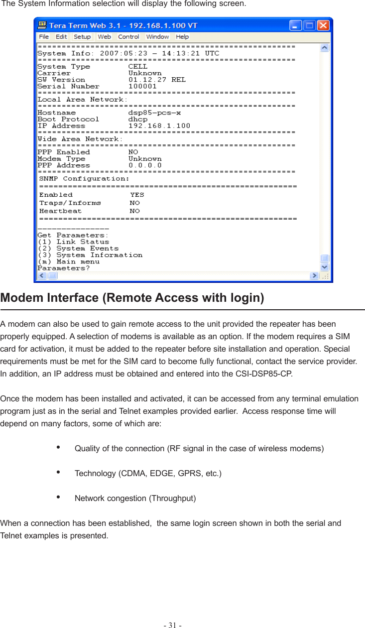
Westell CSI-DSP85-CP Dual Band Bidirectional Amplifier User Manual D960 1038 003 r003 DSPII MANUAL FCC pmd

Westell, Inc. Dual Band Bidirectional Amplifier D960 1038 003 r003 DSPII MANUAL FCC pmd

Exhibit D Users Manual per 2 1033 c3

CSI-DSP85-CPInstallation Manual
Table Of ContentsProduct Registration Information........................................1Document Purpose/Intended Users...................................1Application..........................................................................1Safety Guidelines...............................................................1Manual used Terms............................................................2Product Introduction...........................................................2DSP Filter Naming Convention.............................3-4Functional Overview..............................................5LED Indicators.......................................................5-6Local Communications Interface Ports.....................7Pin-out Chart........................................................7USB Interface........................................................8Ethernet.................................................................8Monitoring & Alarms..............................................8Troubleshooting.....................................................8 Mounting the CSI-DSP85-C/P..............................9Optional Accessories..........................................................10Important Installation Notes................................................10Important Safety Information.............................................. 11Circuit Description.............................................................. 11Function Block Diagram.........................................12Mechanical Specifications......................................13AC Power Specifications........................................13Operating Power Parameters................................14Environmental Requirements.................................14Mechanical Drawing............................................................15Web Based GUI Session....................................................16-21Command Line Interface (Local Access,)...........................22-27Telnet Session (Remote Access, Login Required).............27-31Modem Interface (Remote  Access with Login)..................31Product Warranty................................................................32FCC Information.................................................................32
- 1 -ApplicationThis guide should be applied whenever a need exists to add Digital Repeater capability to anexisting system or when this capability is being included with a new installation.Safety GuidelinesThe general safety information in this guideline applies to both operating and service personnel.Specific warnings and cautions will be found in other parts of this manual where they apply, butmay not appear in this summary. Failure to comply with these precautions or specific warningselsewhere in the manual violates safety standards of design, manufacture, and intended use ofequipment. Cellular Specialties, Inc. assumes no liability for the customer’s failure to comply withthese requirements:GroundingThis Digital Repeater system is designed to operate from 100-240 VAC and should alwaysbe operated with the ground wire properly connected. Do not remove or otherwise alter thegrounding lug on the power cord.Explosive AtmospheresTo avoid explosion or fire, do not operate this product in the presence of flammablegases or fumes.Lightning DangerDo not install or make adjustments to this unit during an electrical storm. Use of a suitablelightning arrester, such as CSI’s model number CSI-CAP, is very strongly recommended.No User Serviceable Parts InsideHAZARDOUS VOLTAGES ARE PRESENT WHEN THE COVER IS REMOVED. Opening thechassis will void your warranty. If you suspect a malfunction with this product, call your dealer orthe Cellular Specialties Support Line at: (603) 626-6677, Toll Free (USA) 1-877-844-4274.The serial number may be found on the label on the rear panel of the unit. Note thisnumber below. Retain this manual, along with proof of purchase, to serve as apermanent record of your purchase.MODEL NUMBER SERIAL NUMBER DATE OF PURCHASEPOINT OF SALE COMPANYProduct Registration InformationDISCLAIMER: All information and statements contained herein are accurate to the best of the knowledge of Cellular Specialties,Inc. (CSI), but Cellular Specialties makes no warranty with respect there to, including without limitation any results that may beobtained from the products described herein or the infringment by such products of any proprietary rights of any persons. Use orapplication of such information or statements is at the users sole risk, without any liability on the part of Cellular Specialties, Inc.Nothing herein shall be construed as licence or recommendation for use, which infringes upon any proprietary rights of any person.Product material and specifications are subject to change without notice. Cellular Specialties’ standard terms of sale and thespecific terms of any particular sale apply.Document Purpose / Intended UsersThe purpose of this document is to provide a step-by-step procedure to help the experiencedtechnician/engineer install and commission an in-building wireless enhancement repeatersystem using CSI’s “Wireless Engine” Digital Repeater. Following the procedures outlined willminimize risks associated with modifying a live system and preclude service interruptions. Thisdocument assumes the technician/engineer understands the basic principles and functionalityinvolved with Repeater and in-building systems. It is geared to the practical concerns of theinstaller.
- 2 -Product IntroductionCellular Specialties, Inc. (CSI) developed the Wireless Engine digital repeater for use within enclosedstructures where sufficient signal from local cell sites to operate cell phones is unavailable. Adequatesignal must be available outside the structure as a prerequisite to achieving in-building coverage. TheDigital Repeater is connected to an external antenna, usually on the roof, and to one or more internalantennas placed strategically throughout the area where wireless service is desired.The external antenna typically is directional, such as a “yagi”. Internal antennas are typically omnidirec-tional, although various other types may be used depending on the coverage application. The CSI’s DSPRepeater amplifies both the “uplink”(phone to tower) & “downlink”(tower to phone) signals thus facilitatingcommunications to and from the intended wireless infrastructure.With a maximum total of +85dB nominal gain on both the up and down links, gain can be adjusted over arange from +55dB to +85dB in 0.5dB steps. Control of the repeater is achieved utilizing a computerconnected to comm. port 1 or 2 or via Ethernet cable connected to the Ethernet port. There are also LEDindicators near the display to indicate ALARM status, AGC status, UL PWR, DL PWR, OSC, SHUT DWNand a D/L SIGNAL STRENGTH bargraph.A specific filtering process modifies each amplification chain. This process digitally converts the assignedspectrum and then applies digital signal processing (DSP) techniques. DSP is used to create passbandsthat selects the RF energy passing through either the uplink or downlink paths. After the digital processingis complete, the information is converted back to an analog signal that is applied to the remaining stagesof amplification. The resulting signals emitted by the repeater are specific to the network service providers’requirements. If these requirements change, only the DSP configuration parameters need change in orderto adapt. Configuration parameters are created at the factory and supplied as files that may be down-loaded to the repeater. The filter set configurations stored in memory determine the unit’s adaptability tovarious field applications. The following pages describe the Cellular and PCS band plans as well as theconvention CSI uses to identify and store the files that make up the filter set.Terms used in this manualAGC = Automatic Gain Control ERP = Effective Radiated PowerAPC = Automatic Power Control FPGA = Field Programmable Gate ArrayAUI = Attachment Unit Interface LED = Light Emitting DiodeCLI = Command line Interface RF = Radio FrequencyCPU = Central Processing Unit SBC = Single board ComputerCSI = Cellular Specialties, Inc. USB = Universal Serial BusDSP = Digital Signal Processing UHCI = Universal Host Controller InterfaceEEPROM = Electrically Erasable   Programmable read-   only Memory
Cellular Frequency Band PlanUpLink DownLinkSMR800iDEN806 821 824 825 835 845 846.5 849 851SMR800iDEN866 869 870 880 890 891.5 894A” A”A B A’ B’ A B A’ B’DownLink UpLink764 776 794 806PS700 PS700 UpLink896 901 935 940SMR900 SMR900DownLinkBUFFERBUFFER894- 3 -Note: All frequencies are shown in MHz
PCS Frequency Band PlanUpLink1850 1865 1870 1885 1890 1895 1910DABBUFFEREF CDownLink1945 1950 1965 1970 1975 1990DABEFC1930A1 UL 1857.5-1865DL 1937.5-1945 A2 UL 1850-1857.5DL 1930-1937.5 A3 UL 1850-1855DL 1930-1935 A4 UL 1855-1860DL 1935-1940 A5 UL 1860-1865DL 1940-1945B1 UL 1877.5-1885DL 1957.5-1965 B2 UL 1870-1877.5DL 1950-1957.5 B3 UL 1870-1875DL 1950-1955 B4 UL 1875-1880DL 1955-1960 B5 UL 1880-1885DL 1960-1965C1 UL 1902.5-1910DL 1982.5-1990 C2 UL 1895-1902..5DL 1975-1982.5 C3 UL 1895-1900DL 1975-1980 C4 UL 1900-1905DL 1980-1985 C5 UL 1905-1910DL 1985-1990C6 UL 1895-1897.5DL 1975-1977.5 C7 UL 1897.5-1900DL 1977.5-1980 C8 UL 1900-1902.5DL 1980-1982.5 C9 UL 1902.5-1905DL 1982.5-1980A” UL 1860.9-1865DL 1940.9-1945- 4 -Note: All frequencies are shown in MHz
- 5 -Functional OverviewThe CSI-DSP85-C/P repeater incorporates the following features for convenient operation,access, protection, and control.•Network Configuration and Control using  either a webpage style GUI through any standard  browser or a menu driven user interface using the serial port. Note: GUI does not require Internet access.•User Gain Control (affects all passbands)•Automatic Gainl Control•Automatic Power Control•Oscillation Protection•Over Drive Protection (P.A. limiting)•Under/Over Voltage Protection•Fault Protection•Alarm Notification - Local/Remote•Upgrade Support - Local/Remote•External Interfaces - USB/Ethernet/Serial•Re-loadable filters - Local/Remote•Web-based monitoring and control - Local/Remote•Persistent Status and Error informationLED IndicatorsAutomatic safety precautions are built into the amplifier system. In the case of a catastrophic systemevent, a shutdown circuit is incorporated that will disable all emissions should the uplink input or downlinkinput be overdriven or should an oscillation or output overpower event occur. The amplifier will periodicallyattempt to recover from the detected condition automatically. Warning light indicators are as follows:
- 6 -AGC: Indicated by a yellow LED. The gain of the unit has been reduced in order toprevent very strong input signals from overloading the amplifier. The amplifier willattempt to recover from this condition at periodic intervals.UL PWR: Indicated by a red LED. Uplink power has been affected by a system event andwill need to  been addressed by either the system software or a technician tobe reset to original system settings, using the GUI or menu driven user interface.See the event log to determine the nature of the fault.DL PWR: Indicated by a red LED. Downlink power has been affected by a system eventand will need to be addressed by either the system software or a technician tobe reset to original system settings, using the GUI or menu driven user interface.See the event log to determine the nature of the fault.OSC: Indicated by a red LED. An oscillation event has occurred or is occurring. Thesystem has been affected by the event and  the problem will need  to beaddressed by the system software or  a technician to be reset to original systemsettings. This is an indication of a major fault.SHUT DWN: Indicated by a red LED. The RF stages of the unit are disabled due to anunresolved system event such as oscillation, effectively taking the unit off theair. The problem will need to be addressed by a technician before the on airoperation can be restarted. The repeater is not equipped with an ON/OFFpower switch, for a hard power down the unit is unplugged.D/L SIGNALSTRENGTH: Indicated by a green LED bargraph. This indicates the relative signal strengthbeing received from the cell site. Note: the last bar of the bargraph will turnred in the event of very strong adjacent channel interference.        Approximate Signal Strengths of Bargraph DisplayILLUMINATED      BARSSIGNAL AT INPUT  CONNECTOR0*12310< -85 dBm-85dBm to -82dBm-81dBm to -79dBm-78dBm to -75dBmAdjacent Channel     Interference456789-74dBm to -71dBm-70dBm to -67dBm-66dBm to -63dBm-62dBm to -59dBm-58dBm to -55dBm-54dBm to -51dBm*Note:  During Power up, the CSI-DSP85-CP will require        a few moments for the internal computer to boot       up. During this time the LEDs on the front panel will       light and go out several times. When boot  is           complete the CSI logo will be lit. Part of the LED       bargraph may also be lit,depending on the strength       of the signal being received from the donor site.       Signals weaker than-85dBM will not illuminate any        bars.Alarm: Indicated by a red LED. The unit has sensed an alarm condition. This LED maylight alone or in conjuction with one of the other indicator LEDs. In both cases thecause(s) can be review by going to the System Health menu.
EIA232 Pin SpecificationsThe diagram above is for reference only, it’s intended to provide a quick source for pinoutinformation in the event it should be necessary to adapt your serial cable because of anunusual connector configuration.  In the vast majority of cases this information will not beneeded.Local Communication Interface PortsTo allow monitoring and control, the CSI-DSP85-CP is equipped with four ports that provideexternal communication access (1 Ethernet CAT-5, 2 DB-9 serial, and 1 USB). The Ethernet,CAT-5 port is provided as a primary communications port to the PC. One serial interfaceprovides communications to local PC and the second to an external modem when provided. TheUSB interface provides a means to download files from a memory device and may also be usedby an internal or external modem.  The DB-9 pin assignments conform to the standard Elec-tronic Industries Association (EIA232) specification. A diagram of the pin descriptions isprovided on this page  for reference.Connecting a null modem cable to one of the COM ports and using a terminal emulationprogram with a PC will allow communication to the control processor’s Command Line Interface(CLI). See command line interface section for further detail.- 7 -
- 8 -USB InterfaceThe Universal Serial Port (USB) interface conforms to Intel’s Universal Host ControllerInterface (UHCI) version 1.1 dated March 21, 1996. This interface will support datatransfer rates up to 12 Mbps.EthernetThe Ethernet AUI conforms to IEEE 802.3 and is capable of supporting 10/100 Mbpscommunications speeds.Monitoring & AlarmsThere are no physical connections provided to specifically communicate system status oralarm status. This information is embedded in data accessible via the communicationports described earlier.TroubleshootingAll cables should be checked for shorts and opens.The rooftop antenna (Donor Antenna), if directional, should be checked for properalignment along the calculated compass heading. Typically, the directional antenna wouldbe aimed at the same site that your handset uses, but it may not always be so. It iscritical the installer contact the service provider for information on, andapproval of the cell site he or she has selected before the system is turnedon.If cables and alignment are acceptable and the problem persists, it may be necessary touse a spectrum analyzer to examine the signal environment in which the CSI-DSP85-CPis operating. The existence of strong  signals within the frequency bands can cause theAGC to reduce the amplifier’s gain. In some cases additional filtering might be required toreject these unwanted signals. In some instances, the directional outside antenna can bereoriented horizontally, to place the interference source in an antenna pattern “null”. Therealso may be some cases where the interference from outside signals is so great that theycannot be filtered or otherwise reduced or eliminated without expensive and possiblyprohibitive measures. In these cases it may not be practical to use the CSI-DSP85-CP forproviding coverage to these sites.
-9 -Wall Mounting the CSI-DSP85-CP, “Frequency Agile Repeater”The following diagram illustrats the best method for mounting the repeater to a wall in atypical installation. Note: for optimal cooling the unit should be mounted vertically on awall with the antenna ports up.ITEM # QTY PART # DESCRIPTION  1 1EA CS10-370-403 DSP85-CP REPEATER  2 2EA 453-1010-001 24V POWER SUPPLY  3 2EA 780-0510-001 LINE CORD (AC POWER)  4 1EA 750-2171-001 MOUNTING PLATE (OPTIONAL)  5 2EA 750-2172-001 P/S MOUNTING BRACKET
- 10 -Optional AccessoriesA complete line of accessories is available from Cellular Specialties, Inc. Check with your CSIdistributor for any addtional items needed.  Below are just a few examples suitable for most in-building needs.•Outside Donor AntennaPCS - model number CSI-AY/1.85-1.99/10      Cellular - model number: CSI-AY/806-960/14•Inside Omnidirectional AntennaPCS - model number (CSI-AS/1.85-1.99/2)     Tri-band - model number (CSI-AO/800/2.5K/3)•Power Dividers2:1 - model number (CSI-S2BSC)3:1 - model number (CSI-S3BSC)4:1 - model number (CSI-S4BSC)•Grounding Kit - model number (CSI-GKIT)•Lightning Arrestor - model number (CSI-CAP)•Directional Couplers and Cross Band Couplers are also available.6dB - model number (CSI-DC6/800-2K/N)10dB - model number (CSI-DC10/800-2K/N)15dB - model number (CSI-DC15/800-2K/N)20dB - model number (CSI-DC20/800-2K/N)30dB - model number (CSI-DC30/800-2K/N)Important Installation Notes•Inadequate isolation between the outside and inside antennas may cause re-generativefeedback in the system. This feedback can cause the amplifier to emit a continuous signal atmaximum amplitude and, in some cases, interfere with normal operation of the cell site. Carefulconsideration of the layout and placement of the system is imperative.•The installer should refer to the safety precautions, in the following section, for proper antennaselection and installation. To avoid serious injury or death and damage to the repeater do not installdonor or server antennas near overhead power lines or high power components.   Allow enoughdistance so that if antennas should fall they will not come in contact  with those components.•••••Close proximity  to the donor or server antennas with the repeater in operation may exposethe user or installer to RF fields that exceed FCC limits for human exposure.WARNING!  AMPLIFIER OR HANDSET DAMAGE MAY OCCUR IF A HANDSET IS CONNECTEDDIRECTLY TO THE REPEATER OR THE COAX THAT LEADS TO THE REPEATER.
Important Safety InformationAntennas used for the purpose of radiating signals indoors are limited to a maximum gain of 3 dBi. Theoutdoor antenna used for the purpose of communicating to the wireless infrastructure is limited to 14dBigain, or any combination of gain and loss that equates to 14dB at input. Each antenna must be positionedto observe minimum separation requirements from all users and bystanders. The following guidelinesshould be used when considering separation distances.INDOOR antennas must be placed such that, under normal conditions,  personnel cannot come within 20cm. (~8.0 in.) from any inside antenna. Adhering to this minimum separation will ensure that the employeeor bystander cannot exceed RF exposures beyond the maximum permissible limit as defined by section1.1310 i.e. limits for General Population/Uncontrolled Exposure.OUTDOOR antenna must be positioned such that, under normal conditions,  personnel cannot approachcloser than 120 cm. (~4 ft.).A directional antenna having a maximum gain of 14 dBi is used, precautionsshould be taken to prevent personnel from routinely passing through the main radiation beam at adistance closer than specified.Circuit Operational DescriptionThe repeater uses a single down-conversion/up-conversion scheme. There are multiple  RF amplifierstages prior to each down-converting mixer. The down-converting mixers are followed by a single IFamplifier. A Digital Signal Processor block then processes the resultant digitized IF signal that waspreviously generated by an Analog-to-Digital Converter. The processed (filtered) digital signal is fed to aDigital-to-Analog converter and then up-converted to RF. A driver amplifier and a final power amplifiermake up the final gain stages before application to the diplexer. The maximum total system gain (diplexerinput to diplexer output) is nominally 85 dB for either the downlink  or the uplink paths with both linkshaving independent manual and automatic gain controls (AGC).AGC reacts to analog power detection on both the input and output of the uplink and downlink RFchains. A control algorithm continuously monitors these detected values and dynamically adjustsvarious gain stages  such that the net system gain value, entered manually, is maintained withouteither exceeding FCC parameters or overdriving the A/D converters.LEDs on the front panel display provide immediate visual indications of the unit’s primary power andmajor or minor alarm status. The repeater features automatic shutdown protection as a safetymeasure should excessive drive be applied to the input or an oscillation condition occur. When in aprotected mode, a control algorithm determines the appropriate method of recovery to a normal,previously defined state, or maintains the protection until manually reset. If recovery has beenestablished, the associated LED(s) will either be extinguished or available to be reset. The eventsthat trigger the error will be save in the event log.Digital signal processing is performed concurrently on the complete spectral band allocation.Therefore, in the case of the US PCS band, digitization of 60 MHz (up or down links) is firstaccomplished. Next, “Filter Files” are applied to a mathematical algorithm that has been establishedin a specialized Field Programmable Gate Array (FPGA) processor.The filter file used in the DSP process is stored in nonvolatile memory and recalled when a filter setis required. Remaining sets are stored in flash memory. Because of the size of the filter files,replacing the EEPROM file with one stored in flash memory takes just a few moments.-11 -
- 12 -Functional Block Diagram
Color     Satin BlackAC Power SpecificationsParameter Specification NotesAC Voltage                                       100 - 240 VAC External Power SupplyAC Power Frequency 47 - 63 HzPower Consumption 150 Watts (Max)Box Weight 35.0 / 15.9 lbs/kgBox Thermal Management           Convection cooled Large heatsinkSurface Coating Powder CoatAC Current 3.2 Amps @ 120 VAC1.7 Amps @ 230 VACMechanical SpecificationsParameter Specification NotesRepeater SizeHeight   4.69 in.Width   18.62 in.Depth   19.25 in.-13 -
- 14 -OIP3 Measured with 2 CW tones at 14dBm/toneLiner Output Power + 27 dBm Uplink and DownlinkNoise Figure (Avg)      6.0 dB At Maximum Gain                 Dual Band Operating Power ParametersParameter Specification NotesMaximum RF input Power                  +10 dBmwithout damageLinear Gain  85 dB Factory Calibrated GainPass Band Ripple   +/-1.5 dBAutomatic Gain Control (AGC)  30 dB max In 0.5 dB steps     rangeManual Gain Control   55-85 dB max In 0.5 dB stepsRMS Vector Error(EVM)   3% max TDMA,EDGE,W-CDMA,CDMA2000CDMA RHO   0.98 min CDMA2000, 1x-EVD0Spurious Emissions &Applicable DocumentsFCC -13 dBm max Per FCC part 2, 22, 24Industry Canada -13 dBm maxPropagation Delay       <2.5 usecInput VSWR (Typ)                                 <1.5:1+ 41 dBmEnvironmental RequirementsParameter Specification NotesRelative Humidity 5% to 95% Non-condensingIndustrial Dust    <15mg/m3 Telcordia GR-63-CORETemperature Range                          -30  to +48  C                                                          (-22  to +118  F)00001dB Compression Uplink and Downlink+ 31 dBmConnectors  N-Female (2)
 Mechanical DrawingINSI DEANTENNAOUTSIDEANTE NNAOSCSHUT DWNUL PWRDL PWRAGCALARMSIGNALD/LSTRENGTHOSCSHUT DWNUL PWRDL PWRAGCALARMSIGNALD/LSTRENGTHMODEM INPUTHIGH  BANDLOW BANDCOM 2 CO M  1 USB ETHERNETLOW BAND HIGH BAND-15 -
-16 -When login is complete the user is brought to the system status page. The links on the page areactivated by clicking on them. Note: some of the settings available in the CLI are not available in theGUI session.Web based GUI SessionPrimary access to the repeater can is  gained thru a LAN connection and a web browserprogram such as Firefox by Mozilla, or Internet Explorer from Microsoft.  The repeater ships withthe default IP address of 192.168.1.100, but it can be changed as required and in the followingexamples we will be using an address of 192.168.1.41.If connecting directly to the CSI-DSP85-CP from a laptop or PC with a crossover CAT-5E cableor over a LAN the user only needs to type the IP address of the repeater into the browseraddress line to connect. At this point the user will be prompted for a user name and password.For the purpose of the GUI session, the default user name is dualband and the password iscsi1234. Please note this can be changed as required. Note: internet accsess is not required touse the GUI.
If the user selects Local Network from the System Status page, the following screen is displayed andfrom here network configuration can be modified as required. The default is set to Static, check withyour IT department for explanation and approval of the DHCP and DHCP Server options before youseletct them.After any changes are made press the refresh button to review the fields and assure thechange made is correct. Note: changing network settings may cause the current TCP/IP connec-tion to fail because change will  take effect immediately.- 17 -
- 18 -From here the user may return to the System Status screen or click on the other options. If the userwould like to modify RF configuration click on the words RF Configuration in the brown navigationbox and the screen below is displayed.The user inputs the gain value desired. Gain values from 53.5 dB to 85.0 dB may be selected. Therepeater will not allow the user to set values outside this range. If a new filter set is required, the newfilter may be selected from the “Program a Filter page” below.
The user may select the desired filter from the dropdown menu.  Pressing the Program button willcomplete the selection and load the desired filter. Note: the time required to complete this processwill take just a few moments.  Note: If the filter desired is not currently in the list, additional filtersalong with instructions on how to load them are available by contacting CSI.When the CSI-DSP85-CP includes an internal modem requiring provisioning for the serviceproviders network  click on Remote Network in the brown navigation box and the screen below isdisplayed.- 19 -
- 20 -Highlight the carrier for whom you want to configure the modem for and click theChange Settings button. Note: the system will require restart for the change to take effect.By clicking System Health the current state of the CSI-DSP85-CP can be reviewed.
To end the session exit  the browser, the user will be automatically logged out.Clicking Diagnostics will bring up the page shown below. The Diagnostics page will show addi-tional data not found on the System Status page.If a reboot of the repeater becomes necessary click on the Reboot option in the brown navigationbox and the Reboot page is displayed.- 21 -
-22 -Command Line Interface (Local Access)Local access to  the CSI-DSP85-CP CLI, also known as the console interface, is made byconnecting a serial cable, as shown in figure 1, from  the serial connector of the laptop to ether ofthe serial ports on the bottom end panel of the FAR. These connectors are labled COM 1 and COM2. In some cases, if the gender of the connector is not the same as shown, a null modem adapteras shown in figure 2 may also be required.Figure 1Figure 2
Many  terminal emulation programs will work if properly configured.  In the following description,“TeraTerm” is used to establish the CLI session. This program is readily available via the Internetand is free from Ayera Technologies at:http://www.ayera.com/teraterm/TeraTerm Pro Web works on Windows 95/98, 2000, XP. Here is the latest TeraTerm Pro Webrelease:Version 3.1.3, October 8, 2002. ttpro313.zipWhen the program is started, the following screen is displayed.Select the Serial radio button and press OK as shown below.Note: It may be necessary, in the System Properties section of the control panel; using DeviceManager to determine what COM port your computer uses for the communications port. In this caseit is COM 1. This is not to be confused with the serial port on the bottom panel of the FAR labledCOM 1- 23 -
-24 -Pressing “OK” will open up a blank dialog screen. Go to the setup dropdown menu andselect Serial port to make changes to the serial port setup.Configure the terminal program for the correct COM port, in this case COM 1 and 115200baud rate as shown below.
After completing the serial port changes, the user will be prompted for a user name andpassword. In dual band units each band is changed independently and requires an independentlogin. To make changes to the cellular band, the default user name is “cellband”. The pass-word for both bands is “csi1234”. The user name for changing the PCS band is “pcsband”.After entering the password and pressing return the  CLI main menu will appear.The actions displayed are self-explanatory. Pressing “1” will continue to expand this sessionscreen and allow the following parameters to be set.-25 -
- 26 -Each “Set Parameter” selection, when chosen will be expanded to allow changing or setting of thatparameter.After selecting option 1, downlink, the current user gain is displayed and the option to change it isaccomplished by typing the desired gain at the prompt. The user is then returned to the previousmenu.
All the other options operate in much the same way. Some of the options will offer the useradditional selections and will be self-explanatory. Below is one example of these additional options,this one for filter selection.Note: Graceful session termination is important. Use Disconnect under the file dropdown menuto terminate a session, otherwise the port may become disabled and force the system to berebooted.Telnet Session (Remote Access)Remote access to the repeater may be gained through a LAN connection and a terminal emula-tion program for TCP/IP. As with the serial connection CSI suggests the use of TeraTerm. In thefollowing description, again, “Teraterm” is used to establish the Telnet session. Also, it will berequired that the network configuration of the computer and the repeater being controlled be setup with the same Sub Net and Sub Net Mask in order to establish a link.In other words, the IP addresses of both the computer used and the repeater must use the samegroup of IP address number sets. For example, the repeater ships with the default IP address of192.168.1.100 and a Sub Net Mask of 255.255.255.0. In order to connect, the computer to beused for the link would normally need an IP address of something like 192.168.1.12 with a SubNet Mask of 255.255.255.0, the same Sub Net Mask as the repeater. In this example note: thelast digit of the IP address may be any number except 1,100 and 255,  Configuring your PC isnormally fairly straight forward but because it does vary somewhat with the operating systeminvolved, this manual will not detail the procedure. If you require assistance, contact your ITdepartment and they will be able to set up your PC for you.When the Tera Term program is started, the following screen is displayed. Change the default hostIP address to the IP address of the repeater to be controlled. In the case of a new install, thedefault address is 192.168.1.100 and has been assigned at the factory. Select the service Telnet.The TCP Port must be 23.- 27 -
- 28 -Pressing the “OK” button will bring the user to the following screen, which will require the user tolog in. In dual band units, each band is changed independently and requires an independentlogin. To make changes to the cellular band the default user name is “cellband”. The defaultuser name for changing the PCS band is “pcsband”.In the field after the prompt “DSP85-PCS-X login;” type the user name for the band to be changed.The default password is “csi1234” for both bands. After typing the password press the enter keyand the main menu will be displayed as shown next.
Telnet and serial sessions both provide access to the same CLI interface. We havealready shown many of the options available with the Set Parameters selection, so nextyou will find examples of the screens and options available when Get Parameters andSystem Commands are chosen.- 29 -
- 30 -Selection of Link Status will provide useful information about the current repeater status andperformance. Below is an example of the status screen.Selection of the System Events option will bring up the following set of sub-options.
The System Information selection will display the following screen.Modem Interface (Remote Access with login)A modem can also be used to gain remote access to the unit provided the repeater has beenproperly equipped. A selection of modems is available as an option. If the modem requires a SIMcard for activation, it must be added to the repeater before site installation and operation. Specialrequirements must be met for the SIM card to become fully functional, contact the service provider.In addition, an IP address must be obtained and entered into the CSI-DSP85-CP.Once the modem has been installed and activated, it can be accessed from any terminal emulationprogram just as in the serial and Telnet examples provided earlier.  Access response time willdepend on many factors, some of which are:•Quality of the connection (RF signal in the case of wireless modems)•Technology (CDMA, EDGE, GPRS, etc.)•Network congestion (Throughput)When a connection has been established,  the same login screen shown in both the serial andTelnet examples is presented.- 31 -
- 32 -One Year Limited WarrantySeller warrants that its products are transferred rightfully and with good title;that its products are free from any lawful security interest or other lien orencumbrance unknown to Buyer; and that for a period of one year from thedate of installation or fifteen months from the date of original shipment, which-ever period expires first, such products will be free from defects in material andworkmanship which arise under proper and normal use and service. Buyer’sexclusive remedy hereunder is limited to Seller’s correction (either at its plantor at such other place as may be agreed upon between Seller and Buyer) ofsuch defects by repair or replacement at no cost to Buyer. Transportation costsin connection with the return of products to Seller’s plant or designated facilityshall be paid by Buyer. The provisions of this warranty shall be applicable withrespect to any product which Seller replaces pursuant to it. SELLER MAKESNO WARRANTY, EXPRESS OR IMPLIED, OTHER THAN AS SPECIFICALLYSTATED ABOVE. EXPRESSLY EXCLUDED ARE THE IMPLIED WARRANTIESOF MERCHANTABILITY AND FITNESS FOR PURPOSE. THE FOREGOINGSHALL CONSTITUTE ALL OF SELLER’S LIABILITY (EXCEPT AS TO PATENTINFRINGEMENT) WITH RESPECT TO THE PRODUCTS. IN NO EVENTSHALL SELLER BE LIABLE FOR SPECIAL, CONSEQUENTIAL OR INCIDEN-TAL DAMAGES, INSTALLATION COSTS, LOST REVENUE OR PROFITS, ORANY OTHER COSTS OF ANY NATURE AS A RESULT OF THE USE OFPRODUCTS MANUFACTURED BY THE SELLER, WHETHER USED INACCORDANCE WITH INSTRUCTIONS OR NOT. UNDER NO CIRCUM-STANCES SHALL SELLER’S LIABILITY TO BUYER EXCEED THE ACTUALSALES PRICE OF THE PRODUCTS PROVIDED HEREUNDER. No represen-tative is authorized to assume for Seller any other liability in connection withthe products.Industry Certifications/Registration Numbers:FCC: NVRCSI-DSP85-CP
- 33 -Notes
Notes- 34 -
960-1038-003  rev004

Navigation menu