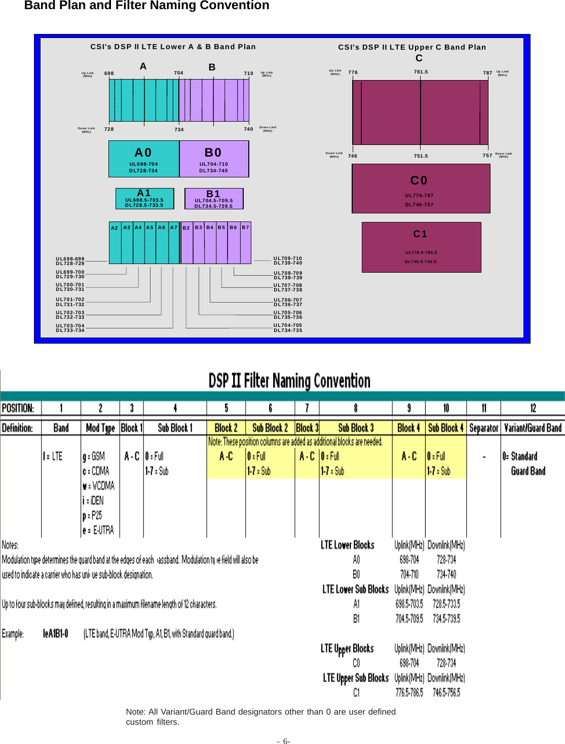
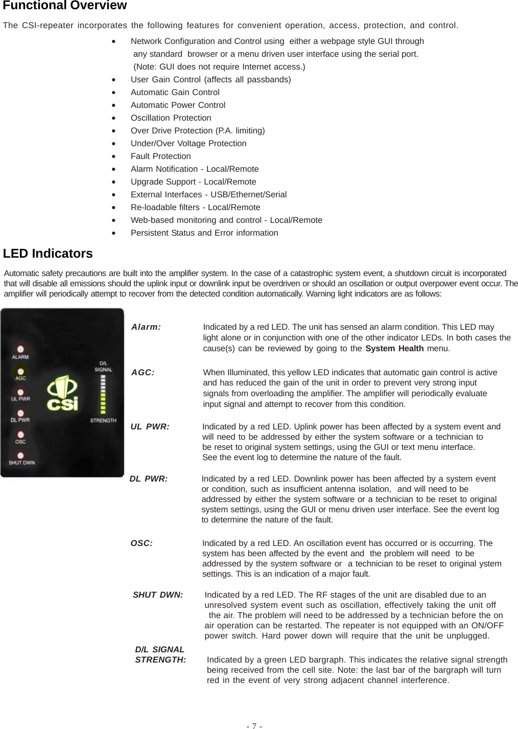
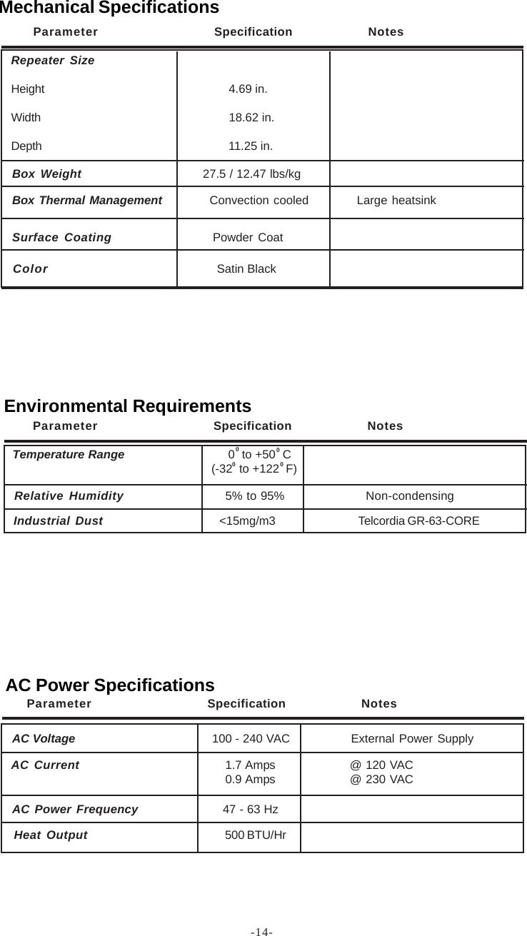
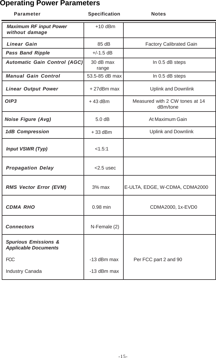
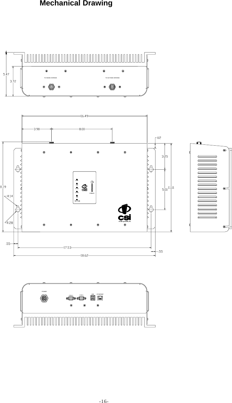
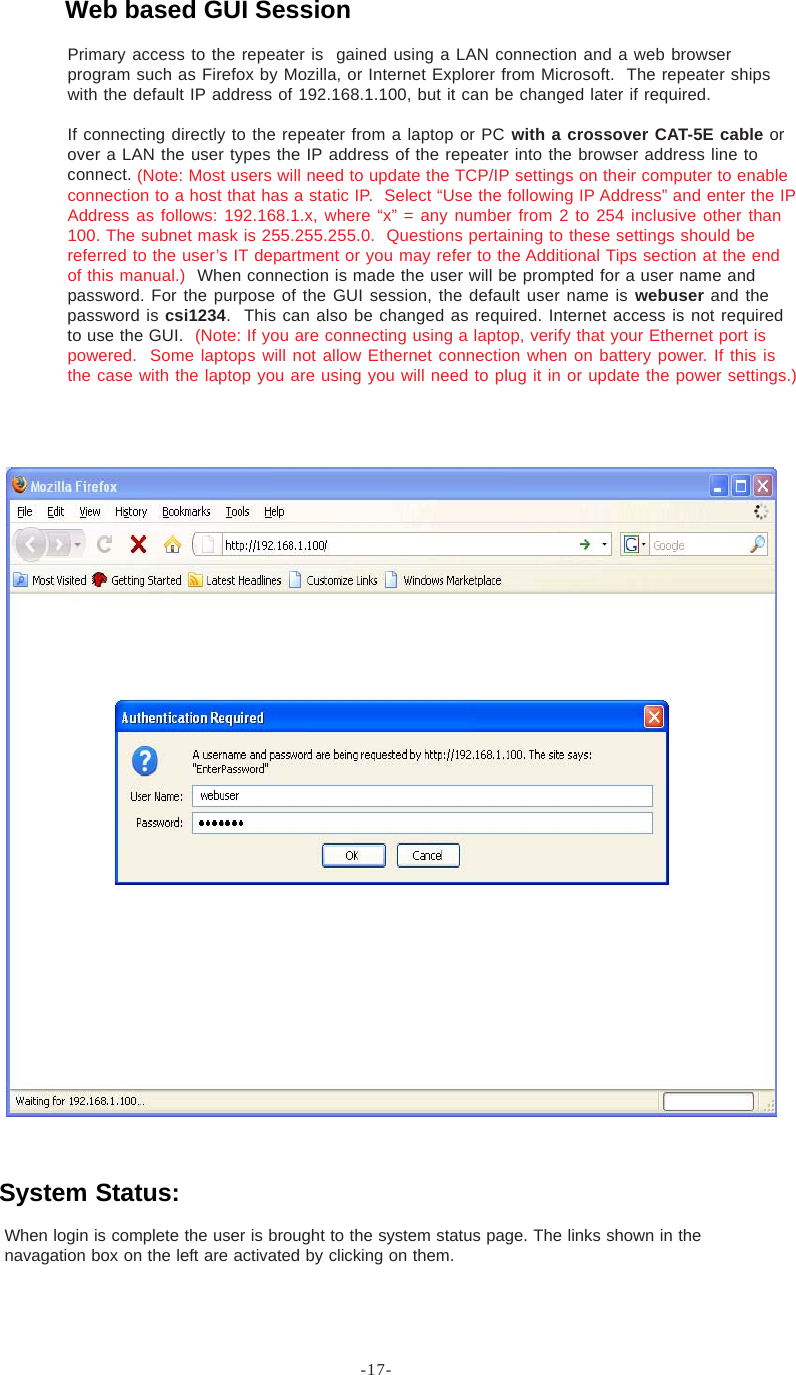
Westell CSI-DSP85-L7AB DSP85 DIGITAL REPEATER LTE 700 MHz LOWER A AND B BAND User Manual D960 1041 009 rA MANUAL SINGLE LTE A B AND C pmd

Westell, Inc. DSP85 DIGITAL REPEATER LTE 700 MHz LOWER A AND B BAND D960 1041 009 rA MANUAL SINGLE LTE A B AND C pmd

Users Manual

   CSI-DSP85-L7AB/CSI-DSP85-U7C                    Installation Manual
Table of ContentsDocument Purpose / Intended Users ................................................................................................................................. 4Application ........................................................................................................................................................................... 4Safety Guidelines ................................................................................................................................................................. 4Product Registration Information....................................................................................................................................... 4Important Safety Information ............................................................................................................................................. 5Product Introduction ........................................................................................................................................................... 5Terms used in this manual ................................................................................................................................................. 5Band Plan and Filter Naming Convention ........................................................................................................................... 6Functional Overview ............................................................................................................................................................ 7LED Indicators ..................................................................................................................................................................... 7Local Communication Interface Ports ............................................................................................................................... 8Approximate Signal Strengths of Bargraph Display ......................................................................................................... 8Ethernet ................................................................................................................................................................................ 8EIA232 Pin Specifications ................................................................................................................................................... 8USB Interface....................................................................................................................................................................... 8Monitoring & Alarms ........................................................................................................................................................... 9System Set-Up Considerations .......................................................................................................................................... 9Selection of external attenuators to be used in line with the Antenna Port(s) ............................................................... 9DONOR PORT ..................................................................................................................................................................... 10SERVER PORT .................................................................................................................................................................... 10Attenuator Selection Guidelines....................................................................................................................................... 10Wall Mounting the Digital Repeater ...................................................................................................................................11Important Installation Notes ............................................................................................................................................. 12Installation Tips ................................................................................................................................................................. 12Optional Accessories ....................................................................................................................................................... 12Circuit Operational Description ........................................................................................................................................ 13Functional Block Diagram ................................................................................................................................................. 13Mechanical Specifications ............................................................................................................................................... 14Environmental Requirements ........................................................................................................................................... 14AC Power Specifications .................................................................................................................................................. 14Operating Power Parameters .......................................................................................................................................... 15Mechanical Drawing.......................................................................................................................................................... 16System Status: .................................................................................................................................................................. 17Web based GUI Session.................................................................................................................................................... 17Local Network:................................................................................................................................................................... 18Program a Filter: ................................................................................................................................................................ 19RF Configuration: ............................................................................................................................................................... 19Remote Network:............................................................................................................................................................... 20SNMP Configuration: ......................................................................................................................................................... 20Install & Upload: ................................................................................................................................................................. 21System Health:................................................................................................................................................................... 21Reboot: ............................................................................................................................................................................... 22Email Configuration: .......................................................................................................................................................... 22Alarm Configuration: ......................................................................................................................................................... 22Log Configuration: ............................................................................................................................................................. 23Text Menu Interface (Local Access) ................................................................................................................................ 23Terminal Emulation Program ............................................................................................................................................ 24Terminal Emulation Set-up ................................................................................................................................................ 25TMI Login ............................................................................................................................................................................ 26Telnet Session (Remote Access) ..................................................................................................................................... 28Telnet Session Login ......................................................................................................................................................... 29Modem Interface (Remote Access with login) ................................................................................................................ 30Additional Tips ................................................................................................................................................................... 31Suggested spectrum analyzer setting:............................................................................................................................ 33RF Notes: ............................................................................................................................................................................ 33Industry Certifications/Registration Numbers:................................................................................................................ 34Index ................................................................................................................................................................................... 35
-4-Product Registration InformationDISCLAIMER: All information and statements contained herein are accurate to the best of the knowledgeof Cellular Specialties, Inc. (CSI), but Cellular Specialties makes no warranty with respect thereto, includingwithout limitation any results that may be obtained from the products described herein or the infringementby such products of any proprietary rights of any persons. Use or application of such information orstatements is at the users sole risk, without any liability on the part of Cellular Specialties, Inc. Nothingherein shall be construed as licence or recommendation for use, which infringes upon any proprietaryrights of any person. Product material and specifications are subject to change without notice. CellularSpecialties’ standard terms of sale and the specific terms of any particular sale apply.The general safety information in this guideline applies to both operating and service personnel.Specific warnings and cautions will be found in other parts of this manual where they apply, butmay not appear in this summary. Failure to comply with these precautions or specific warningselsewhere in the manual violates safety standards of design, manufacture, and intended use ofequipment. Cellular Specialties, Inc. assumes no liability for the customer’s failure to comply withthese requirements:GroundingThis Digital Repeater system is designed to operate from 100-240 VAC and should alwaysbe operated with the ground wire properly connected. Do not remove or otherwise alter thegrounding lug on the power cord.Explosive AtmospheresTo avoid explosion or fire, do not operate this product in the presence of flammablegases or fumes.Lightning DangerDo not install or make adjustments to this unit during an electrical storm. Use of a suitablelightning arrester, such as CSI’s model number CSI-CAP, is very strongly recommended.No User Serviceable Parts InsideHAZARDOUS VOLTAGES ARE PRESENT WHEN THE COVER IS REMOVED. Opening thechassis will void your warranty. If you suspect a malfunction with this product, call your dealer orthe Cellular Specialties Support Line at: (603) 626-6677, Toll Free (USA) 1-877-844-4274.Safety GuidelinesThis guide should be applied whenever a need exists to add Digital Repeater capability to anexisting system or when this capability is being included with a new installation.ApplicationDocument Purpose / Intended UsersThe purpose of this document is to provide a step-by-step procedure to help the experiencedtechnician/engineer install and commission an in-building wireless enhancement repeatersystem using CSI’s Digital Repeater. Following the procedures outlined will minimize risksassociated with modifying a live system and prevent service interruptions. This documentassumes the technician/engineer understands the basic principles and functionality involvedwith Repeater and in-building systems. It is geared to the practical concerns of the installer.The serial number may be found on the label on the bottom panel near the powerconnectors. Note this number below. Retain this manual, along with proof of pur-chase, to serve as a permanent record of your purchase.MODEL NUMBER SERIAL NUMBER DATE OF PURCHASEPOINT OF SALE COMPANYNOTE: This equipment has been tested and found to comply with the limits for a Class A digitaldevice, pursuant to Part 15 of the FCC rules. These limits are designed to provide reasonableprotection against harmful interference when the equipment is operated in a commercialenvironment.  This equipment generates, uses and can radiate radio frequency energy and,if not installed and used in accordance with the instruction manual, may cause harmfulinterference to radio communications. Operation of this equipment in a residential area islikely to cause harmful interference in which case the user will be required to correct theinterference at his own expense.Radio and Television Interference
- 5 -Cellular Specialties, Inc. (CSI) developed the DSP85 digital repeater for use within enclosed structures where signal from local dispatchsites is insufficient to operate on scene communication equipment. Adequate signal must be available outside the structure as a prerequi-site to achieving in-building coverage. The Digital Repeater is connected to an external antenna, usually on the roof, and to one or moreinternal antennas placed strategically throughout the area where wireless service is desired.The external antenna typically is directional, such as a “yagi”. Internal antennas are typically omnidirectional, although various other typesmay be used depending on the coverage application. The CSI DSP Repeater amplifies both the “uplink” (Transceiver to tower) &“downlink”(tower to Transceiver) signals thus facilitating communications to and from the intended wireless infrastructure.With a maximum total of +85dB nominal gain on both the up and down links, gain can be adjusted over a range from +53.5dB to +85dB in0.5dB steps. Control of the repeater is achieved utilizing a computer connected to comm. port 1 or 2 or via a Crossover Ethernet cableconnected to the Ethernet port. There are also LED indicators near the display to indicate ALARM status, AGC status, UL PWR, DL PWR,OSC, SHUT DWN and a D/L SIGNAL STRENGTH bargraph.A specific filtering process modifies each amplification chain. This process digitally converts the assigned spectrum and then appliesdigital signal processing (DSP) techniques. DSP is used to create passbands that selects the RF energy passing through either the uplinkor downlink paths. After the digital processing is complete, the information is converted back to an analog signal that is applied to theremaining stages of amplification. The resulting signals emitted by the repeater are specific to the network service providers’  require-ments. If these requirements change, only the DSP configuration parameters need change in order to adapt. Configuration parameters arecreated at the factory and supplied as files that may be downloaded to the repeater. The filter set configurations stored in memorydetermine the unit’s adaptability to various field applications. The following pages describe the public safety band plan as well as theconvention CSI uses to identify and store the files that make up the filter set. All DSP85 repeaters are shipped with an active filter set thatis programmed according to the ordering parties’ specifications.  In most cases, the installer will not have to program a filter.AGC= Automatic Gain Control ERP= Effective Radiated PowerAPC= Automatic Power Control FPGA= Field Programmable Gate ArrayAUI= Attachment Unit Interface LED= Light Emitting DiodeCPU= Central Processing Unit OIP3= Third-Order Intercept PointCSI= Cellular Specialties, Inc. RF= Radio FrequencyDAS= Distributed Antenna System SBC= Single board Computer              DHCP= Dynamic Host Configuration   SNMP= Simple Network Management Protocol                          Protocol TMI= Text Menu InterfaceDSP= Digital Signal Processing USB = Universal Serial BusEEPROM= Electrically Erasable UHCI = Universal Host Controller Interface  Programmable read-  only MemoryAntennas used for the purpose of radiating signals indoors are limited to a maximum gain of 3 dBi. The outdoor antenna used for thepurpose of communicating to the wireless infrastructure is limited to 14dBi gain, or any combination of gain and loss that equates to14dB at input. Each antenna must be positioned to observe minimum separation requirements from all users and bystanders. Thefollowing guidelines should be used when considering separation distances.INDOOR antennas must be placed such that, under normal conditions,  personnel cannot come within 20 cm (~8.0 in.) from any insideantenna. Adhering to this minimum separation will ensure that the employee or bystander cannot exceed RF exposures beyond themaximum permissible limit as defined by section 1.1310 i.e. limits for General Population/Uncontrolled Exposure.OUTDOOR antenna must be positioned such that, under normal conditions,  personnel cannot approach closer than 120 cm. (~4 ft.). Adirectional antenna having a maximum gain of 14 dBi is used, precautions should be taken to prevent personnel from routinely passingthrough the main radiation beam at a distance closer than specified.Product IntroductionTerms used in this manualImportant Safety Information
- 6-CSI’s DSP II LTE Lower A & B Band PlanUp Link (MHz)Down Link (MHz) 728698A0UL698-704DL728-734B0UL704-710DL734-740A1UL698.5-703.5DL728.5-733.5B1UL704.5-709.5DL734.5-739.5AB704 710734 740Up Link (MHz )Down Link (MHz)A2 A3 A4 A5 A6 A7UL698-699DL728-729UL699-700DL729-730UL700-701DL730-731UL701-702DL731-732UL702-703DL732-733UL703-704DL733-734B2 B3 B4 B5 B6 B7UL704-705DL734-735UL705-706DL735-736UL706-707DL736-737UL707-708DL737-738UL708-709DL738-739UL709-710DL739-740CSI’s DSP II LTE Upper C Band PlanUp Link (MHz)Down Link (MHz) 746776C0UL776-787DL746-757C1UL776.5-786.5DL746.5-756.5C787757Up Link (MHz )Down Link (MHz)781.5751.5Note: All Variant/Guard Band designators other than 0 are user definedcustom filters.Band Plan and Filter Naming Convention
- 7 -The CSI-repeater incorporates the following features for convenient operation, access, protection, and control.•Network Configuration and Control using  either a webpage style GUI through any standard  browser or a menu driven user interface using the serial port. (Note: GUI does not require Internet access.)•User Gain Control (affects all passbands)•Automatic Gain Control•Automatic Power Control•Oscillation Protection•Over Drive Protection (P.A. limiting)•Under/Over Voltage Protection•Fault Protection•Alarm Notification - Local/Remote•Upgrade Support - Local/Remote•External Interfaces - USB/Ethernet/Serial•Re-loadable filters - Local/Remote•Web-based monitoring and control - Local/Remote•Persistent Status and Error informationAutomatic safety precautions are built into the amplifier system. In the case of a catastrophic system event, a shutdown circuit is incorporatedthat will disable all emissions should the uplink input or downlink input be overdriven or should an oscillation or output overpower event occur. Theamplifier will periodically attempt to recover from the detected condition automatically. Warning light indicators are as follows:UL PWR: Indicated by a red LED. Uplink power has been affected by a system event andwill need to be addressed by either the system software or a technician tobe reset to original system settings, using the GUI or text menu interface.See the event log to determine the nature of the fault.DL PWR: Indicated by a red LED. Downlink power has been affected by a system eventor condition, such as insufficient antenna isolation, and will need to beaddressed by either the system software or a technician to be reset to originalsystem settings, using the GUI or menu driven user interface. See the event logto determine the nature of the fault.OSC: Indicated by a red LED. An oscillation event has occurred or is occurring. Thesystem has been affected by the event and  the problem will need  to beaddressed by the system software or  a technician to be reset to original ystemsettings. This is an indication of a major fault.SHUT DWN: Indicated by a red LED. The RF stages of the unit are disabled due to anunresolved system event such as oscillation, effectively taking the unit off                             the air. The problem will need to be addressed by a technician before the onair operation can be restarted. The repeater is not equipped with an ON/OFFpower switch. Hard power down will require that the unit be unplugged.D/L SIGNALSTRENGTH: Indicated by a green LED bargraph. This indicates the relative signal strengthbeing received from the cell site. Note: the last bar of the bargraph will turnred in the event of very strong adjacent channel interference.Alarm: Indicated by a red LED. The unit has sensed an alarm condition. This LED maylight alone or in conjunction with one of the other indicator LEDs. In both cases thecause(s) can be reviewed by going to the System Health menu.AGC: When Illuminated, this yellow LED indicates that automatic gain control is activeand has reduced the gain of the unit in order to prevent very strong inputsignals from overloading the amplifier. The amplifier will periodically evaluateinput signal and attempt to recover from this condition.Functional OverviewLED Indicators
-8-EIA232 Pin SpecificationsThe diagram to the left is for reference only, it’s intended to providea quick source for pinout information in the event it should benecessary to adapt your serial cable because of an unusualconnector configuration.  In the vast majority of cases thisinformation will not be needed.To allow monitoring and control, the repeater is equipped with four ports that provide external communication access (1 EthernetCAT-5, 2 DB-9 serial, and 1 USB). The Ethernet, CAT-5 port is provided as a primary communications port to the PC. One serialinterface provides communications to local PC and the second to an external modem when provided. The  USB interface provides ameans to download files from a memory device and may also be used by an external modem.  The DB-9 pin assignments conformto the standard Electronic Industries Association (EIA232) specification. A diagram of the pin descriptions is provided on this pagefor reference.Connecting a null modem cable to one of the COM ports and using a terminal emulation program with a PC will allow communicationto the control processor’s Text Menu Interface (TMI). See command line interface section for further detail.Approximate Signal Strengths of Bargraph DisplayILLUMINATED      BARS SIGNAL AT INPUT  CONNECTOR0*12310< -81 dBm-81dBm to -79dBm-78dBm to -75dBmAdjacent Channel     Interference456789-74dBm to -71dBm-70dBm to -67dBm-66dBm to -63dBm-62dBm to -59dBm-58dBm to -55dBm-54dBm to -51dBmThe minimum measurable input level is -81 dBm at 85 dB gain, -71 dBm at 75 dB gain,  -61 dBm at 65 dB gain, and -51 dBm at 55 dB gain.The Universal Serial Bus (USB) interface conforms toIntel’s Universal Host Controller Interface (UHCI) version1.1 dated March 21, 1996. This interface will support datatransfer rates up to 12 Mbps and can be used for soft-ware updates and filter file uploads.*Note:  During Power up, the unit will require a approximately three minutes for the internal computer to boot up. During this timethe LEDs on the front panel will light and go out several times. When boot  is complete and no alarm conditions exist, none of the LEDindicators will be illuminated. The CSI logo is illuminated when ever the repeater is powered. One or more bars on the LED bargraphmay also be lit, depending on the strength of the signal being received from the donor site. Signals weaker than -81dBM will notilluminate any bars.                                     Do not unplug the unit while it is in the boot up process!Local Communication Interface PortsUSB InterfaceThe Ethernet AUI conforms to IEEE 802.3 and is capable ofsupporting 10/100 Mbps communications speeds. This port isused to provide access to the GUI.Ethernet
- 9 -All cables should be checked for shorts and opens. Also verify that there are no cables with loose or poor connec-tions. RF leakage could cause oscillation to occur under some conditions.The rooftop antenna (Donor Antenna), if directional, should be checked for proper alignment along the calculatedcompass heading. Typically, the directional antenna would be aimed at the same site that your handset uses, but it maynot always be so. It is critical the installer contact the service provider for information on, and approvalof, the site he or she has selected before the system is turned on.If cables and alignment are acceptable and a problem persists, it may be necessary to use a spectrum analyzer toexamine the signal environment in which the DSP85 is operating. The existence of strong  adjacent channel signalswithin the frequency band(s) can cause the AGC to reduce the amplifier’s gain or cause alarms. In some casesadditional filtering or attenuation might be required to reject these unwanted signals. In some instances, the donorantenna can be reoriented horizontally, to place the interference source in an antenna pattern “null”. There also may besome cases where the interference from outside signals is so great that they cannot be filtered or otherwise reducedor eliminated without expensive and possibly prohibitive measures. In these cases it may not be practical to use theCSI-DSP85 for providing coverage to these sites.TO INSIDE ANTENNA TO OUTSIDE ANTENNA1:1 PORT CONFIGURATION   Input: One single band port, from the single band donor.Output: One single band port to the DAS.There are no physical connections provided to specifically communicate system or alarm status. This information isembedded in the information accessible via the communication ports described earlier.Monitoring & AlarmsSystem Set-Up ConsiderationsSelection of external attenuators to be used in line with the Antenna Port(s)
- 10 -If a CSI-DSP85 is installed in an area with very strong desired and/or undesired signals, it is important to ensure that the overall signal levels areoptimized to be within the best operating range of the repeater.  Additionally, de-sensing of a nearby base station site must be avoided.  These goalscan be accomplished by properly attenuating the antenna port(s) in the path of the donor antenna(s).  In effect, one can imagine that the particularrepeater deployment is electrically moved farther from the base station using attenuators that are equivalent to increasing the path loss from thedonor antenna to the base station. The following potential outcomes result from the use of attenuators on the donor port(s) of the CSI-DSP85:  Uplinkoutput power, as reported by the CSI-DSP85, is reduced by the value of the attenuation, protecting nearby base stations.  Downlink signal to noiseratio is high at the point of the attenuator, resulting in slight but negligible reduction in downlink performance. Other performance is essentiallyunchanged.DONOR PORTServer port attenuation may also be necessary, particularly where a powered DAS is present.  The selection guidelines below apply to both serverand donor ports.  In order to properly measure uplink signal strength, a signal generator should be used.  If a signal generator is not available, placinga test call while under the server antenna with the least path loss to the repeater should provide reasonable data.The following potential outcomes result from the use of attenuators on the server port(s) of the CSI-DSP85:  Downlink output power, as reportedby the CSI-DSP85, is reduced by the value of the attenuation.  Uplink incoming power from the DAS is reduced, along with potentially strong and/or harmful out-of-band signals (including noise) that are generated by the DAS.SERVER PORTAttenuator Selection GuidelinesAccurate attenuator values need to be chosen to ensure that the maximum total power (higher of Composite or In-Band Input) applied to the donorand server port(s) does not exceed the following thresholds:Input Signal Max Gain Input Signal Max Gain                   <-45 dBm 85 dB -32.2 dBm 69 dB                                     -44.3 dBm 84 dB -31.4 dBm 68 dB                                     -43.6 dBm 83 dB  -30.6 dBm 67 dB                                     -42.9 dBm 82 dB  -29.8 dBm 66 dB                                     -42.2 dBm 81 dB  -29 dBm 65 dB                                     -41.5 dBm 80 dB  -28.2 dBm 64 dB                                     -40.6 dBm 79 dB  -27.4 dBm 63 dB                                     -39.7 dBm 78 dB  -26.6 dBm 62 dB                                     -38.8 dBm 77 dB  -25.8 dBm 61 dB                                     -37.9 dBm 76 dB   -25 dBm 60 dB                                     -37 dBm 75 dB   -24.4 dBm 59 dB*                                     -36.2 dBm 74 dB   -23.8 dBm 58 dB*                                     -35.4 dBm 73 dB   -23.2 dBm 57 dB*                                     -34.6 dBm 72 dB   -22.6 dBm 56 dB*                                     -33.8 dBm 71 dB   -22 dBm < 55 dB*                                     -33 dBm 70 dB*We recommend padding this level due to potential for fluctuating signal.-25 dBm is the maximum input signal level that should be applied to the repeater, even if the gain is lower than 55 dB. Input signals exceeding these thresholds will result in composite input attenuation, called “ADC Protect” (Analog to Digital Converter Protection).Output power is reduced whenever the above thresholds are exceeded by reducing the gain by 1dB for each 1 dB that the threshold is exceeded.ADC Protect should not be confused with AGC (Automatic Gain Control), which reduces gain to prevent In-Band (measured) output power fromexceeding the specified maximum output level. To determine the total power applied to the donor and server ports, please reference the “CompositeInput” values as reported in the Web (“System Status”) or Menu (“Link Status”) interfaces (depicted and explained later in this manual).Large delta’s between in-band and composite input signals:Care should be taken to isolate the best donor site to ensure the least possible delta between in-band and composite downlink signals. If the(downlink) composite input exceeds the in-band input by more than 3 dB for the LTE band  the maximum output power will be reduced.  Example:                                                                                                Band  (LTE)                                                                                                In-Band Input -45 dBm                                                                                                Composite Input -38 dBm                                                                                                 Max Gain = 68 dB                                                                                                 Max Output = 23 dBm
- 11 -ITEM # QTY PART # DESCRIPTION  1 1EA CS10-388-409  DSP85-L7AB REPEATER orCS10-388-410             DSP85-L7C REPEATER  2 1EA 453-1010-002 5V/24V POWER SUPPLY  3 1EA 780-0510-001 LINE CORD (AC POWER)  4 1EA 750-2171-001 MOUNTING PLATE (OPTIONAL)  5 1EA 750-2172-002 P/S MOUNTING BRACKETThe following diagram illustrates the best method for mounting the repeater to a wall in an typical installation.Note: for optimal cooling the unit should be mounted vertically on a wall with the antenna ports up.Wall Mounting the Digital Repeater
-12-Warning: power supply cable connectors are keyed for proper orientation, but if forced can be inserted incorrectly.Great care should be taken to avoid this as it may damage the connectors and/or the repeater.Keyed for proper alignment, do not forceconnector into place.A complete line of accessories is available from Cellular Specialties, Inc. Check with your CSI distributor for any additional itemsneeded.  Below are just a few examples suitable for most in-building needs.•Directional Couplers     6dB - model number: CSI-DC6/700-2K/N     10dB - model number: CSI-DC10/700-2K/N     15dB - model number: CSI-DC15/700-2K/N     20dB - model number: CSI-DC20/700-2K/N     30dB - model number: CSI-DC30/700-2K/N•Outside Donor Antenna      Panel - model number: CSI-AP/698/2.2K/7-10•UPS      Battery backup, 2 hr Single band      1 hour dual band - model number: CS48-985-600 Battery backup, 4 hr Single band 2 hour dual band - model number: CS48-985-601•Power Dividers      2:1 - model number: CSI-SPD2/700-2.5K/N      3:1 - model number: CSI-SPD3/700-2.5K/N      4:1 - model number: CSI-SPD4/700-2.5K/N•Grounding Kit - model number: CSI-GKIT•Lightning Arrestor - model number: CSI-CAP•Inside Omnidirectional Antenna      Quad-band - model number: CSI-AO/700/2.5K/3  •Mounting Kit  19” rack or wall mountable -  model number: CSI-RWM-DSP85Optional Accessories•       Inadequate isolation between the outside and inside antennas may cause regenerative feedback in the system. This feedbackcan cause the amplifier to emit a continuous signal at maximum amplitude and, in some cases, interfere with normal operation of thedonor site. Careful consideration of the layout and placement of the system is imperative to minimize this possibility and to minimizethe amount of signal leaking from the building. See installation tips below for general guidelines.•The installer should refer to the Safety Guidelines section on page 4 and the Important Safety Information section on page 5 forproper antenna selection and installation. To avoid serious injury or death and damage to the repeater, do not install donor or serverantennas near overhead power lines or high power components.   Allow enough distance so that if antennas should fall they will notcome in contact  with those components.•••••Close proximity  to the donor or server antennas with the repeater in operation may expose the user or installer to RF fields thatexceed FCC limits for human exposure.WARNING!  AMPLIFIER OR HANDSET DAMAGE MAY OCCUR IF A HANDSET IS CONNECTED DIRECTLY TO THE REPEATER OR THE COAXTHAT LEADS TO THE REPEATER.Important Installation NotesDonor Antenna1. Accurately determine  the azimuth to the donor cell site . Obtain the donor site information and approval fromthe service provider/carrier.2. Ensure that the radiation path to the donor cell site is as unobstructed as possible.3. Mount the donor antenna at or toward the edge of the roof, in the direction of the donor site. Try to avoid having theRF signal from the donor pass above the location(s) of the service antennas.  Normally the service antennas will bebehind and below the donor antenna if viewed from above. This approach will help avoid interference and feed backboth, to and from the service antennas.4. Normally mounting the donor antenna higher will allow a less obstructed path to the donor site.  However, in hightraffic metro areas avoid mounting the donor antenna any higher than necessary as the quality of the donor signal maystart to become less stable and it is more likely to encounter adjacent channel interference.5. When possible shield the donor antenna’s back side by locating it so that any HVAC units and/or penthouse struc-tures are behind the antenna relative to the donor cell site location.Installation TipsIndoor Antennas1. Use omnidirectional antennas (see optional accessories) indoors, and locate them centrally with respect to theintended coverage area to minimize signal leakage to the outside. Use directional antennas indoors only in special caseswhen higher gain and directionality would be helpful and RF exposure limits will not be exceeded.2. To avoid repeater uplink overload and gain limiting mount the indoor antennas away from areas where mobile subscrib-ers frequently use their phones such as desks or dispatch areas.
-13-The repeater uses a single down-conversion/up-conversion scheme. There are multiple  RF amplifier stages prior to each down-convertingmixer. The down-converting mixers are followed by a single IF amplifier. A Digital Signal Processor block then processes the resultant digitizedIF signal that was previously generated by an Analog-to-Digital Converter. The processed (filtered) digital signal is fed to a Digital-to-Analogconverter and then up-converted to RF. A driver amplifier and a final power amplifier make up the final gain stages before application to thediplexer. The maximum total system gain (diplexer input to diplexer output) is nominally 85 dB for either the downlink  or the uplink paths withboth links having independent manual and automatic gain controls (AGC).AGC reacts to analog power detection on both the input and output of the uplink and downlink RF chains. A control algorithm continu-ously monitors these detected values and dynamically adjusts various gain stages  such that the net system gain value, enteredmanually, is maintained without either exceeding FCC parameters or overdriving the A/D converters.Circuit Operational DescriptionFunctional Block DiagramUpon detection of oscillation the unit will shut down.  After a “short duration” of 30 seconds the unit will attempt normal operation.  If no continuedoscillation is occurring the unit will stay on. However, if oscillation is still occurring, the repeater will remain shut down and retry 1 additional time inthe “short duration” loop.  If after these two “short duration” retries, the oscillation is still detected, it will turn off again and wait a “long duration” periodof 10 minutes.  If after 6 “long duration” retries, oscillation continues,  the unit  will go into a “disable duration” of 24 hours. It will continue in the “disableduration” loop and retry every 24 hours.LEDs on the front panel display provide immediate visual indications of the unit’s primary power and major or minor alarm status. Therepeater features automatic shutdown protection, as a safety measure, should excessive drive be applied to the input or an oscillationcondition occur. When in a protected mode, a control algorithm determines the appropriate method of recovery to a normal, previouslydefined state, or maintains the protection until manually reset. If recovery has been established, the associated LED(s) will either beextinguished or available to be reset. The eventsthat trigger the error will be saved in the event log.Indoor Antennas continued3. To determine the quantity and locations of indoor antennas, use an appropriate phone's signal meter to determine areasof weak signals. These are the approximate areas where indoor antennas may be needed. Also be aware the signal froman indoor antenna, in most cases, can be expected to penetrate about two standard office sheetrock type walls to reachusers. After two walls or if the walls are made of other materials, it may be necessary to split the available signal and addmore antennas.
-14-Color     Satin BlackAC Voltage                                       100 - 240 VAC External Power SupplyAC Power Frequency 47 - 63 HzBox Weight 27.5 / 12.47 lbs/kgBox Thermal Management           Convection cooled Large heatsinkSurface Coating Powder CoatAC Current 1.7 Amps @ 120 VAC0.9 Amps @ 230 VACRepeater SizeHeight   4.69 in.Width   18.62 in.Depth   11.25 in.Heat Output 500 BTU/HrParameter Specification NotesMechanical SpecificationsAC Power SpecificationsParameter Specification NotesEnvironmental RequirementsRelative Humidity 5% to 95% Non-condensingIndustrial Dust    <15mg/m3 Telcordia GR-63-CORETemperature Range                             0  to +50  C                                                           (-32  to +122  F)000   0Parameter Specification Notes
-15-OIP3 Measured with 2 CW tones at 14dBm/toneLinear Output Power + 27dBm max Uplink and DownlinkNoise Figure (Avg)      5.0 dB At Maximum GainMaximum RF input Power                  +10 dBmwithout damageLinear Gain  85 dB Factory Calibrated GainPass Band Ripple   +/-1.5 dBAutomatic Gain Control (AGC)  30 dB max In 0.5 dB steps     rangeManual Gain Control  53.5-85 dB max In 0.5 dB stepsRMS Vector Error (EVM)   3% max            E-ULTA, EDGE, W-CDMA, CDMA2000CDMA RHO   0.98 min CDMA2000, 1x-EVD0Spurious Emissions &Applicable DocumentsFCC -13 dBm max Per FCC part 2 and 90Industry Canada -13 dBm maxPropagation Delay       <2.5 usecInput VSWR (Typ)                                 <1.5:1+ 43 dBm1dB Compression Uplink and Downlink+ 33 dBmConnectors  N-Female (2)Operating Power ParametersParameter Specification Notes
-16-ETHERNETUSBCOM 1COM 2POWER DL PWRALARMUL PWRTO OUTSIDE ANTENNATO INS IDE ANTENNAMechanical Drawing
-17-When login is complete the user is brought to the system status page. The links shown in thenavagation box on the left are activated by clicking on them.Primary access to the repeater is  gained using a LAN connection and a web browserprogram such as Firefox by Mozilla, or Internet Explorer from Microsoft.  The repeater shipswith the default IP address of 192.168.1.100, but it can be changed later if required.If connecting directly to the repeater from a laptop or PC with a crossover CAT-5E cable orover a LAN the user types the IP address of the repeater into the browser address line toconnect. (Note: Most users will need to update the TCP/IP settings on their computer to enableconnection to a host that has a static IP.  Select “Use the following IP Address” and enter the IPAddress as follows: 192.168.1.x, where “x” = any number from 2 to 254 inclusive other than100. The subnet mask is 255.255.255.0.  Questions pertaining to these settings should bereferred to the user’s IT department or you may refer to the Additional Tips section at the endof this manual.)  When connection is made the user will be prompted for a user name andpassword. For the purpose of the GUI session, the default user name is webuser and thepassword is csi1234.  This can also be changed as required. Internet access is not requiredto use the GUI.  (Note: If you are connecting using a laptop, verify that your Ethernet port ispowered.  Some laptops will not allow Ethernet connection when on battery power. If this isthe case with the laptop you are using you will need to plug it in or update the power settings.)System Status:Web based GUI Session
-18-If the user selects Local Network from the System Status page, the following screen is displayedand from here network configuration can be modified as required. The default is set to Static. Checkwith your IT department for explanation and approval of the DHCP and DHCP Server options youplan to use before you select them. *NOTE:  In units with software version 2.2.4 or prior, onlyletters, numbers and underscores are acceptable nomenclature.  In units with software version2.3.0 and up, Underscores are not acceptable; however, hyphens are acceptable.After any changes are made press the refresh button to review the fields and ensurethe change made is correct. Note: changing network settings will cause the current TCP/IPconnection to fail because the change will  take effect immediately. From here the user may returnto the System Status screen or click on the other options.Local Network:
-19-If the user would like to modify RF configuration click on the words RF Configuration in thenavigation box and the screen below is displayed.The user inputs the gain value desired. Gain values from 53.5 dB to 85.0 dB may be selected. Therepeater will not allow the user to set values outside this range. If a new filter set is required, the newfilter may be selected from the “Program a Filter page” below.The user may select the desired filter by pressing the band/sub-band and modulation selectionbuttons. Undesired bands/sub-bands if lit will require the user to manually “deselect” them beforeprogramming.   Pressing the Program button will complete the selection and load the desired filter.The time required to complete this process will take just a few moments.  Note: If the filter desiredis not currently in the unit, additional filters along with instructions on how to load them areavailable by contacting CSI.RF Configuration:Program a Filter:
-20-To change SNMP settings click SNMP Configuration in the navigation box, the screen below will bedisplayed. If the user is not well versed in Simple Network Management Protocol he or she shouldcheck with their IT professional for proper setting requirements.If the repeater includes a modem kit, click on Remote Network in the navigation box and the screenbelow is displayed.Highlight the carrier on whose network the repeater and modem will be configured and click theChange Settings button. Refer to the documentation included with the modem kit for addtionalinformation on configuring the modem.Remote Network:SNMP Configuration:
-21-By clicking System Health the current state of the repeater can be reviewed.Should a software install or upgrade be needed it can be done from the Install & Upload screenshown below. As with the other screens it can be reached by clicking the words in thenavigation box. Contact CSI for updates and instructions.System Health:Install & Upload:***The user may clear LED indicators, alarms and the Event Log by clicking the Clear Log button.******* If required in your municipality, visit the “System Health” screen and click on “Trigger TestAlarm” and wait for confirmation that the Service Provider representative that is responsiblefor monitoring the repeater has been notified of the alarm. Be sure to “Clear All Logs” prior tologging out of the Web Interface.****
-22-If a reboot of the repeater becomesnecessary click on the Reboot option in thenavigation box and the Reboot page isdisplayed.Reboot: Alarm Configuration:The Alarm Configuration page allows the user to specify whatevents will trigger an alarm.*NOTE:  Letters, numbers & hyphens are the onlyacceptable nomenclature for the Location field and hyphensmay not be used as the first or last character.Email Configuration page allows the user to enter up to five Email addresses to which the repeater can send specifiedalarm messages when Email Alarm Notification and Remote Networking are enabled, and the repeater is equipped withan active wireless modem.  *NOTE:  In all fields the software will not allow the user to enter invalid characters.Email Configuration:
-23-To end the session exit  the browser, the user will be automatically logged out.The Log Configuration page provides the user with the means to modify three aspects of howlog files are created and stored as shown below.Log Configuration:Figure 1 Figure 2Local access to  the repeater TMI, also known as the console interface, is made by connecting a serialcable (optional), as shown in figure 1, from  the serial connector of the laptop to either of the serial ports onthe bottom end panel of the repeater. These connectors are labeled COM 1 and COM 2. In some cases, ifthe gender of the connector is not the same as shown in figure 1, a null modem adapter (optional) as shownin figure 2 may also be required.Text Menu Interface (Local Access)
-24-Many terminal emulation programs will work if properly configured.  In the following description,“TeraTerm” is used to establish the TMI session. This program is readily available via the Internetand is free from Ayera Technologies at:http://www.ayera.com/teraterm/TeraTerm Pro Web works on Windows 95/98, 2000, XP. Here is the latest TeraTerm Pro Webrelease: Version 3.1.3, October 8, 2002. ttpro313.zipWhen the program is started, the following screen is displayed.Select the Serial radio button and press OK as shown below.Note: It may be necessary, in the System Properties section of the control panel; using DeviceManager to determine what COM port your computer uses for the communications port. In this caseit is COM 1. This is not to be confused with the serial port on the bottom panel of the repeaterlabeled COM 1.Terminal Emulation Program
-25-Pressing “OK” will open up a blank dialog screen. Go to the setup dropdown menu andselect Serial port to make changes to the serial port setup.Configure the terminal program for the correct COM port, in this case COM 1 and 115200baud rate as shown below.Terminal Emulation Set-up
-26-After completing the serial port changes (pressing the enter key will be required to completethe action) the user will be prompted for a user name and password. The default user name is“user”. The password is “csi1234”.  After entering the password and pressing return theTMI main menu will appear. Note: by default the Set Parameters option is disabled. To re-enablethe user will press 1 and will be prompted for a username and password.   The default username is csi and the password is csi1234.The actions displayedare self-explanatory.Pressing “1” willcontinue to expand thissession screen andallow the followingparameters to be set.TMI Login
-27-After selecting option 1, downlink, the current user gain is displayed and the option to change itis accomplished by typing the desired gain at the prompt. The user is then returned to theprevious menu.Each “Set Parameter” selection, when chosen will be expanded to allow changing or setting of thatparameter. For example from the Link Configuration menu on the previous page, selecting 1 - AdjustGain will display the menu shown below.
-28-All the other options operate in much the same way. Some of the options will offer the useradditional selections and will be self-explanatory. Below is one example of these additional options,the one shown below is the result of selecting (3) Filter Programming.Note: Graceful session termination is important. Use Disconnect under the file dropdown menuto terminate a session, otherwise the port may become disabled and force the system to berebooted.Remote access to the repeater may be gained through a LAN connection and a terminalemulation program for TCP/IP. As with the serial connection, many terminal emulation programswill work, if properly configured.  In the following description, “TeraTerm” is used to establish theTelnet session. Also, it will be required that the network configuration of the computer and therepeater being controlled be set up with the same Sub Net and Sub Net Mask in order to establisha link. In other words, the IP addresses of both the computer used and the repeater must use thesame group of IP address number sets. For example, the repeater ships with the default IPaddress of 192.168.1.100 and a Sub Net Mask of 255.255.255.0. In order to connect, thecomputer to be used for the link would normally need an IP address of something like192.168.1.12 with a Sub Net Mask of 255.255.255.0, the same Sub Net Mask as the repeater. Inthis example note: the last digit of the IP address may be any number except 1,100 and 255.Configuring your PC is normally fairly straight forward but it does vary somewhat with theoperating system involved.  If you require assistance, contact your IT department and they willbe able to set up your PC for you or you may review the Additional Tips Section at the end of themanual.When the TeraTerm program is started, the following screen is displayed. Change the defaulthost IP address to the IP address of the repeater to be controlled. In the case of a new install, thedefault address is 192.168.1.100 and has been assigned at the factory. Select the serviceTelnet. The TCP Port must be 23.Telnet Session (Remote Access)
-29-Pressing the “OK” button will bring the user to the following screen, which will require the userto log in.  The default user name is “user”. The default password is “csi1234”.In the field after the prompt “DSP85-cell-X login;” type the user name and password. After typingthe password press the enter key and the main menu will be displayed as shown next.Telnet Session Login
-30-Telnet and serial sessions both provide access to the same Text Menu Interface. Wehave already shown many of the options available and all are self explanatory, so theywill not be repeated.A modem can also be used to gain remote access to the unit provided the repeater has beenproperly equipped. A selection of modems is available as an option. If the modem requires a SIMcard for activation, special requirements must be met for the SIM card to become fully functional,contact the service provider. In addition, an IP address must be obtained and entered into the CSI-DSP85-PSS8.Once the modem has been installed and activated, it can be accessed from any terminal emulationprogram just as in the serial and Telnet examples provided earlier.  Access response time willdepend on many factors, some of which are:•Quality of the connection (RF signal in the case of wireless modems)•Technology (CDMA, EDGE, GPRS, etc.)•Network congestion (Throughput)When a connection has been established,  the same login screen shown in both the serial andTelnet examples is presented.Modem Interface (Remote Access with login)
-31-Instructions to change TCP/IP settings on your Windows computer.Click in the Network Connections Icon in the Control Panel. See below.Right click on Local Area Connection - and select “Properties”.Scroll down to “Internet Protocol (TCP/IP) and click on the “Properties” button.Additional Tips
-32-If you are set up to use DHCP, the window shown below will be displayed.Select “Use the following IP address:” and enter “192.168.1.2.”  The subnet maskshould automatically populate to “255.255.255.0”.Nothing else will need  to be chosen or entered. Click “OK”, then “OK again andretry connection.A crossover Ethernet cable (supplied) must be used for Web Interface access.  Asa reminder, you must verify the Ethernet port on your laptop is powered. If yourlaptop is on battery power, the Ethernet port may be inactive by default.  If this isthe case simply plug in the laptop to a 110vac source or change the power settingsto enable the Ethernet port when the laptop is using battery power.
-33-When  troubleshooting RF issues,  and when surveying challengingRF environments, it’s important to have a spectrum analyzer capableof measuring the frequency that you are working with.  An attenua-tor should be used to protect the input, when connected to a sourceof RF power such as the repeater or a powered DAS.Both Uplink and Downlink should be measured.  Downlink should bemeasured on the donor cable and at the output (server) port of thepowered up repeater, and Uplink at the lead from the DAS (on fiber/powered DAS’s, where the lead would connect to the server port onthe repeater) and at the donor port with the repeater powered up.Measurements may also be necessary at server antenna locations.Your spectrum analyzer will need to be equipped with a whipantenna for this.Resolution Bandwidth (RBW) should be set at 200 kHz for GSM and 1MHz for CDMA.  If you cannot select these values, the closestavailable values should be used.  Video filter should be about onetenth of RBW.  Other settings like span are whatever is appropriate.One should also make sure that there are no signals above the topof the screen.If you cannot see an adjacent out of band signal when using the 1MHz RBW filter, you can decrease the RBW, to see the close-in-frequency signals.  Be sure to set the RBW back when you want tomeasure the power level.Suggested spectrum analyzer setting:RF Notes:To prevent overload of the DSP input stages, the maximum measuredlevel of in-band or out of band signals should be less than -50 dBm whenthe DSP gain is set to 85 dB, -40 dBm when set to 75 dB, etc.  This applieswhen there is one dominant signal and applies TO BOTH THE DOWNLINKAND UPLINK.  If there are two dominant signals, and the gain is set to 85dB, then the level of each signal should be kept to less than -53 dBm.With three signals, each should be less than -55 dBm.  With ten signalseach should be less than -60 dBm.  This latter reduction prevents thecomposite power of the multiple signals from exceeding an acceptablelevel.  Add fixed attenuators in line with the donor antenna line/DAS feedto keep signals below the levels indicated above.
-34-Seller warrants that its products are transferred rightfullyand with good title; that its products are free from any lawfulsecurity interest or other lien or encumbrance unknown toBuyer; and that for a period of one year from the date ofinstallation or fifteen months from the date of original ship-ment, whichever period expires first, such products will befree from defects in material and workmanship which ariseunder proper and normal use and service. Buyer’s exclusiveremedy hereunder is limited to Seller’s correction (either atits plant or at such other place as may be agreed upon be-tween Seller and Buyer) of such defects by repair or replace-ment at no cost to Buyer. Transportation costs in connectionwith the return of products to Seller’s plant or designatedfacility shall be paid by Buyer. The provisions of this war-ranty shall be applicable with respect to any product whichSeller replaces pursuant to it. SELLER MAKES NO WAR-RANTY, EXPRESS OR IMPLIED, OTHER THAN AS SPECIFI-CALLY STATED ABOVE. EXPRESSLY EXCLUDED ARE THEIMPLIED WARRANTIES OF MERCHANTABILITY AND FIT-NESS FOR PURPOSE. THE FOREGOING SHALL CONSTI-TUTE ALL OF SELLER’S LIABILITY (EXCEPT AS TO PATENTINFRINGEMENT) WITH RESPECT TO THE PRODUCTS. INNO EVENT SHALL SELLER BE LIABLE FOR SPECIAL, CON-SEQUENTIAL OR INCIDENTAL DAMAGES, INSTALLATIONCOSTS, LOST REVENUE OR PROFITS, OR ANY OTHERCOSTS OF ANY NATURE AS A RESULT OF THE USE OFPRODUCTS MANUFACTURED BY THE SELLER, WHETHERUSED IN ACCORDANCE WITH INSTRUCTIONS OR NOT.UNDER NO CIRCUMSTANCES SHALL SELLER’S LIABILITYTO BUYER EXCEED THE ACTUAL SALES PRICE OF THEPRODUCTS PROVIDED HEREUNDER. No representative isauthorized to assume for Seller any other liability in connec-tion with the products.FCC: NVRCSI-DSP85-L7AB, NVRCSI-DSP85-L7C IC: 4307A-DSP85-L7AB, 4307A-DSP85-L7COne Year Limited WarrantyIndustry Certifications/Registration Numbers:
-35-IndexAAC Current  14AC Power Frequency  14AC Power Specifications  14AC Voltage  14Additional Tips  31AGC  5AGC:  7Alarm  7Alarm Configuration  22APC  5Application  4AUI  5Automatic Gain Control  15BBargraph Display  8Box Weight  14CCDMA RHO  15Circuit Operational Description13, 18, 19, 20, 21, 22Connectors  15CPU  5CSI  5DD/L SIGNALSTRENGTH:  7DAS  5Depth  14DHCP  5DL PWR  7Document Purpose / Intended Users4DSP  5EEEPROM  5Email Configuration:  22Environmental Requirements  14ERP  5Event Log  21Explosive Atmospheres  4FFPGA  5Functional Block Diagram  13Functional Overview  7GGrounding  4HHeight  14IILLUMINATED      BARS  8Important Installation Notes  12Important Safety Information  5Inadequate isolation  12Industrial Dust  14Industry Certifications/RegistrationNumbers  34Input VSWR  15Install Software  21LLED  5LED Indicators  7Lightning Danger  4Linear Gain  15Liner Output Power  15Local Network  18login  17MManual Gain Control  15Maximum RF input Power  15Modem Interface  30modulation selection  19Monitoring & Alarms  9NNoise Figure  15null modem adapter  23OOIP3  15OSC  7PPass Band Ripple  15Power supply cable connectors  12Product Registration Information  4Program a Filter  19Propagation Delay  15RReboot  22Relative Humidity  14Remote Network  20Resolution Bandwidth  33RF Configuration  19RF Notes  33RMS Vector Error  15SSBC  5serial cable  23SHUT DWN  7SNMP  5SNMP Configuration  20Spurious Emissions  15Suggested spectrum analyzer setting33Surface Coating  14System Health  21System Status  18TTCP/IP settings  31Telnet Session  28, 29Temperature Range  14terminal emulation programs  24Terms used in this manual  5Thermal Management  14TMI  5troubleshooting RF issues  33UUHCI  5UL PWR  7USB  5USB Interface  8WWall Mounting  11Warranty  34Web based GUI Session  17Width  14
-36-Notes
-37-Notes
-38-Notes
-39-Notes
960-1041-009  rev A  ECO 2266

Navigation menu