Westell CSI310-03 Bidirectional amplifier User Manual
Westell, Inc. Bidirectional amplifier
UserManual.wiki
>
Westell
>
CSI310-03 User Manual
>
User Manual
Contents
1.
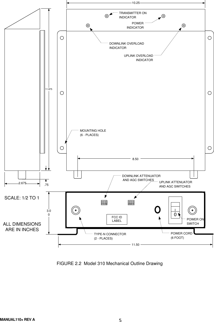
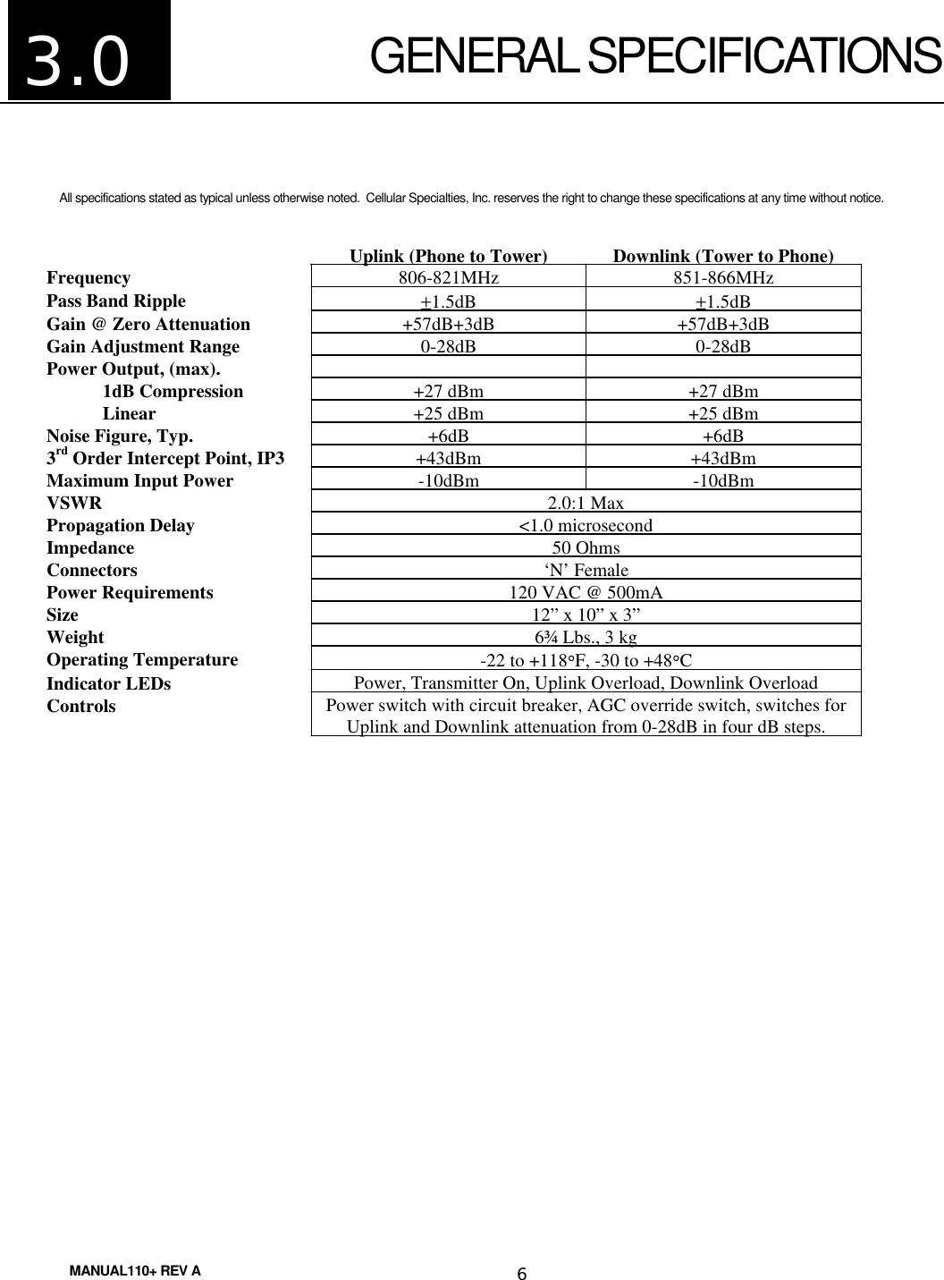
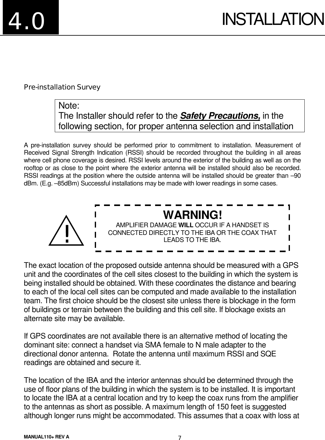
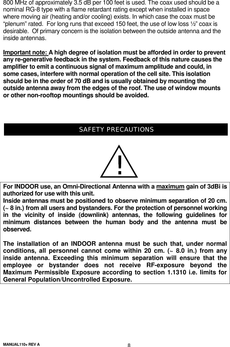
User Manual
2.
User Manual March 2000
User Manual
Navigation menu
Upload a User Manual
Namespaces
Wiki Guide
HTML
PDF
Info
Views
User Manual
Discussion / Help
Navigation