Westell CSI610-04 Bidirectional Amplifier User Manual 610smr 900 Usermanual Omni
Westell, Inc. Bidirectional Amplifier 610smr 900 Usermanual Omni
Westell >
Exhibit D Users Manual per 2 1033 c3

Model 610SMR -900In-Building Amplifier
Installation and Users Manual
Cellular Specialties, Inc.

MANUAL 610 SMR-OMNI 1
DISCLAIMER
All information and statements contained herein are accurate to the best of the knowledge of Cellular Specialties, but Cellular Specialties makes no warranty
with respect thereto, including without limitation any results which may be obtained from the products described herein or the infringement by such products of
any proprietary rights of any persons. Use or application of such information or statements is at the user's sole risk, without any liability on the part of Cellular
Specialties, Inc. Nothing herein shall be construed as license or of recommendation for use, which infringes upon any proprietary rights of any person.
Product material and specifications are subject to change without notice. All sales of the product or products described herein are subject to Cellular
Specialties' standard terms of sale and the specific terms of any particular sale.
FCC ID NVRCSI610-04
This device complies with parts 90 and 2 of the
FCC rules
MANUAL610SMR-900 OMNI
2
TABLE OF CONTENTS
1.0 SAFETY GUIDELINES 3
2.0 PRODUCT DESCRIPTION 4
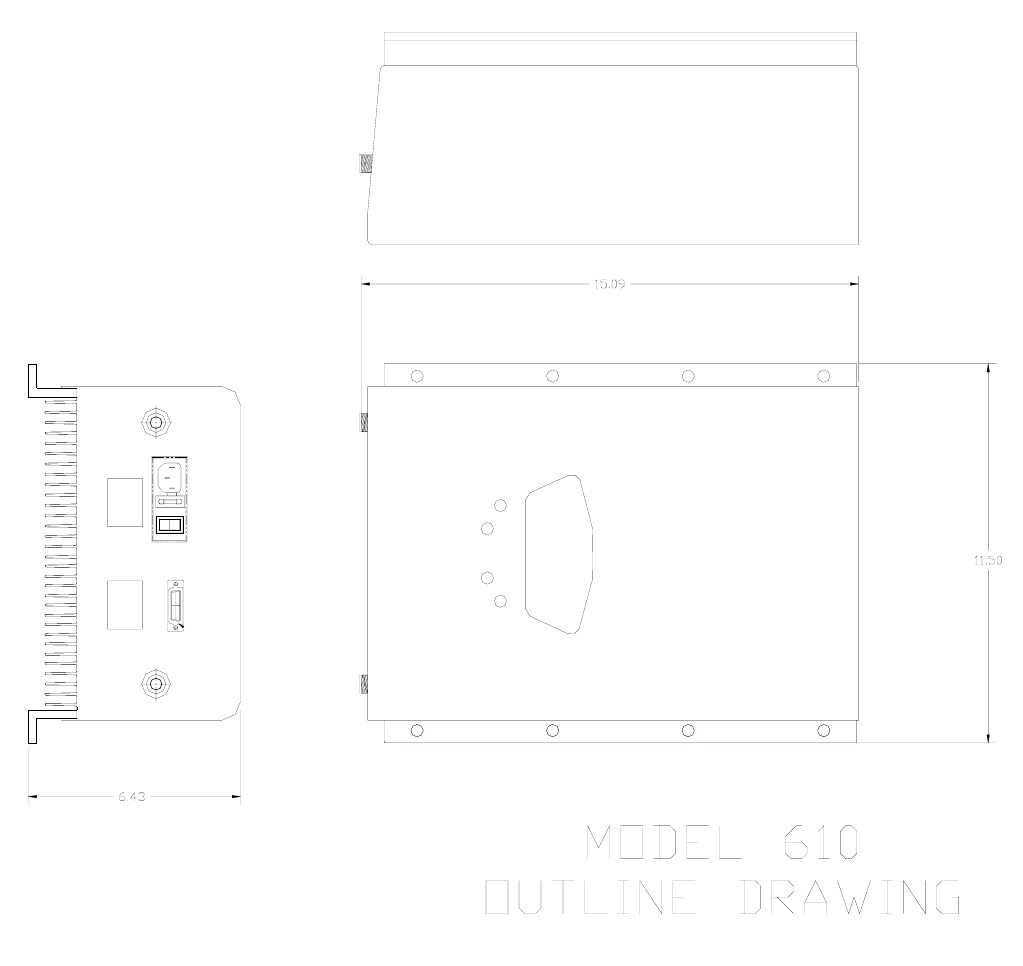
MECHANICAL OUTLINE DRAWING 5
3.0 GENERAL SPECIFICATIONS 6
4.0 INSTALLATION 7
5.0 AMPLIFIER ADJUSTMENT 9
6.0 TROUBLESHOOTING 10

MANUAL610SMR-900 OMNI
3
SAFETY GUIDELINES
GROUNDING
This amplifier system is designed to operate from single-phase 120VAC power and should
always be operated with both the neutral and ground wires properly connected. Do not
remove or otherwise alter the grounding lug on the power cord.
EXPLOSIVE ATMOSPHERES
This product has an integral circuit breaker, which may cause an electrical flash if the
breaker should reset. To avoid explosion or fire, do not operate this product in the presence of
flammable gases or fumes.
LIGHTNING DANGER
Do not install or make adjustments to this unit during an electrical storm.
NO USER SERVICEABLE PARTS INSIDE
HAZARDOUS VOLTAGES ARE PRESENT WHEN THE COVER IS REMOVED.
Opening the chassis will void your warranty. If you suspect a malfunction with this product, call
your dealer or the Cellular Specialties Support Line at (603) 626-6677.
!
The general safety information in this guideline applies to both operating
and service personnel. Specific warnings and cautions will be found in
other parts of this manual where they apply, but may not appear in this
summary. Failure to comply with these precautions or specific warnings
elsewhere in the manual violates safety standards of design,
manufacture, and intended use of equipment. Cellular Specialties, Inc.
assumes no liability for the customer's failure to comply with these
requirements.
1.0
MANUAL610SMR-900 OMNI
4
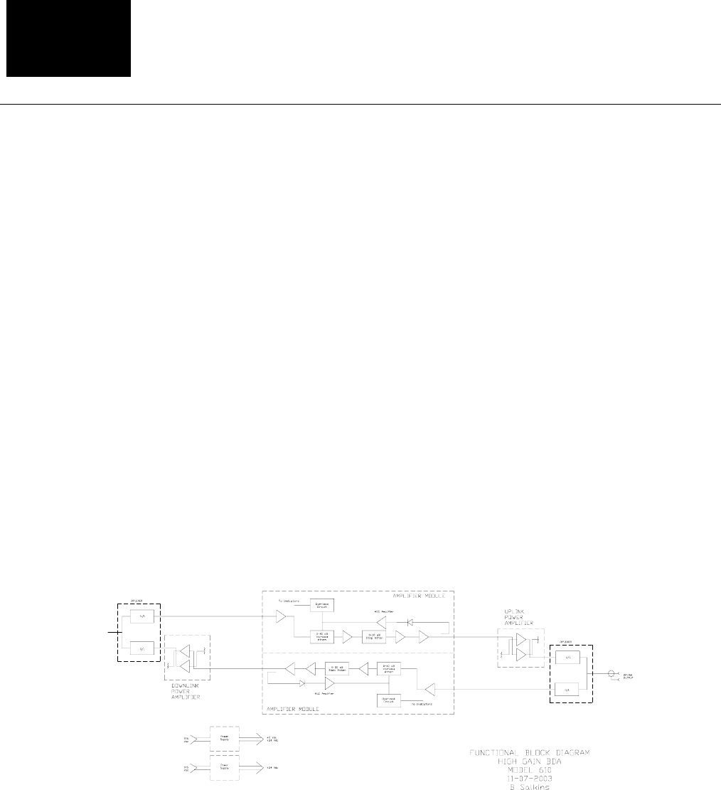
PRODUCT DESCRIPTION
Cellular Specialties, Inc. developed the Model 610smr In-Building Amplifier (IBA) for use in enclosed
structures where sufficient signal from local cell sites to operate cell phones was unavailable within the
building. It is, of course, necessary that sufficient signal be available on the roof of the structure. The
IBA is connected to an external antenna, usually on the roof, and to one or more internal antennas
placed strategically throughout the area where phone service is desired.
The external antenna is an omni-directional antenna, used when the building is located in close
proximity to one or more cell sites. Internal antennas are usually omni-directional although various other
types may be used for certain installations. The IBA amplifies both the "uplink" (phone to tower) and
"downlink" (tower to phone) signals thus facilitating communications to and from the local cell site
There are seven amplification stages on the downlink and seven on the uplink for a total of +85dB
nominal gain for each link. (see Figure 2.1) Both links have manual gain control settings accessed
through DIP switches on the top cover plus an AGC control for both the uplink and downlink. There are
also LED indicators on the top cover for power on, transmitter on, uplink overload and downlink
overload.
An automatic amplifier safety shutdown circuit is also present that will disable the transmitters for ten
seconds should the uplink or downlink overloads be reached to prevent excessive intermodulation and
oscillation.
2.0
MANUAL610SMR-900 OMNI
5
I
O
INSIDE
ANTENNA
OUTSIDE
ANTENNA
AC INPUT MONITOR
FCC / IC
LABEL
SERIAL
NUMBER
MANUAL610SMR-900 OMNI
6
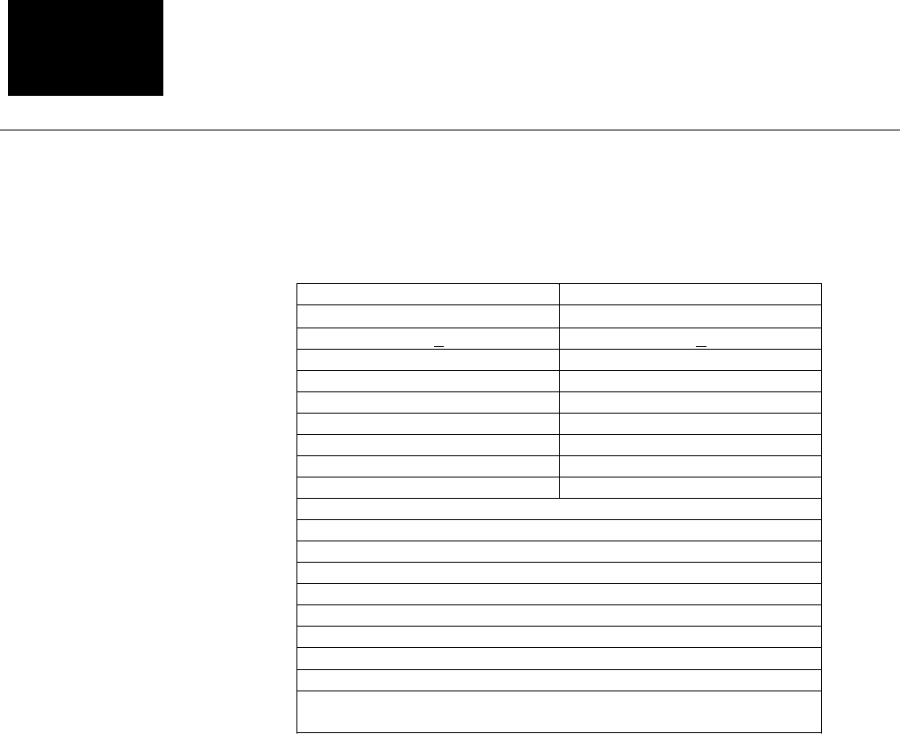
GENERAL SPECIFICATIONS
All specifications stated as typical unless otherwise noted. Cellular Specialties, Inc. reserves the right to change these specifications at any time without notice.
3.0
Uplink (Phone to Tower) Downlink (Tower to Phone)
Frequency 896-901 MHz 935-940 MHz
Pass Band Ripple ±1.5 db ±1.5 db
Gain @ Zero Attenuation +85 dB+3 db +85 dB+3 db
Gain Adjustment Range -28 db -28 db
Power Output, (max).
*Linear +28.1 dBm +30.2 dBm
Noise Figure, Typ. +4.5 db +4.5 db
3rd Order Intercept Point, IP3 +50 dBm +54 dBm
**Maximum Input Power -10 dBm -10 dBm
VSWR 2.0:1 Max
Propagation Delay <1.0 microsecond
Impedance 50 Ohms
Connectors ‘N’ Female
Power Requirements 120 VAC @ 1500mA
Size 15” x 13.5” x 4”
Weight 6¾ Lbs., 3 kg
Operating Temperature -22 to +118°F, -30 to +48°C
Indicator LEDs Power, Transmitter On, Uplink Overload, Downlink Overload
Controls Power switch with fuse, AGC override switch, switches for Uplink
and Downlink attenuation from 0-28dB in four dB steps.
NOTES
*Maximum total output power without exceeding the FCC allowable emissions of –13 dBm.
** Maximum safe input power at maximum gain with no damage.
MANUAL610SMR-900 OMNI
7
INSTALLATION
Pre-installation Survey
Note:
The Installer should refer to the Safety Precautions, in the
following section, for proper antenna selection and installation
A pre-installation survey should be performed prior to commitment to installation. Measurement of
Received Signal Strength Indication (RSSI) should be recorded throughout the building in all areas
where cell phone coverage is desired. RSSI levels around the exterior of the building as well as on the
rooftop or as close to the point where the exterior antenna will be installed should also be recorded.
RSSI readings at the position where the outside antenna will be installed should be greater than –80
dBm. (E.g. –75dBm) Successful installations may be made with lower readings in some cases.
4.0
!
WARNING!
AMPLIFIER DAMAGE WILL OCCUR IF A HANDSET IS
CONNECTED DIRECTLY TO THE IBA OR THE COAX THAT
LEADS TO THE IBA.
MANUAL610SMR-900 OMNI
8
The location of the IBA and the interior antennas should be determined through the
use of floor plans of the building in which the system is to be installed. It is important
to locate the IBA at a central location and try to keep the coax runs from the amplifier
to the antennas as short as possible. A maximum length of 150 feet is suggested
although longer runs might be accommodated. This assumes that a coax with loss at
800 MHz of approximately 3.5 dB per 100 feet is used. The coax used should be a
nominal RG-8 type with a flame retardant rating except when installed in space
where moving air (heating and/or cooling) exists. In which case the coax must be
“plenum” rated. For long runs that exceed 150 feet, the use of low loss ½” coax is
desirable. Of primary concern is the isolation between the outside antenna and the
inside antennas.
Important note: A high degree of isolation must be afforded in order to prevent
any re-generative feedback in the system. Feedback of this nature causes the
amplifier to emit a continuous signal of maximum amplitude and could, in
some cases, interfere with normal operation of the cell site. This isolation
should be in the order of 70 dB and is usually obtained by mounting the
outside antenna away from the edges of the roof. The use of window mounts
or other non-rooftop mountings should be avoided.
SAFETY PRECAUTIONS
For INDOOR use, an Omni-Directional Antenna with a maximum gain of 3dBi is
authorized for use with this unit.
Inside antennas must be positioned to observe minimum separation of 20 cm.
(~ 8 in.) from all users and bystanders. For the protection of personnel working
in the vicinity of inside (downlink) antennas, the following guidelines for
minimum distances between the human body and the antenna must be
observed.
The installation of an INDOOR antenna must be such that, under normal
conditions, all personnel cannot come within 20 cm. (~ 8.0 in.) from any
inside antenna. Exceeding this minimum separation will ensure that the
employee or bystander does not receive RF-exposure beyond the
Maximum Permissible Exposure according to section 1.1310 i.e. limits for
General Population/Uncontrolled Exposure.
!
MANUAL610SMR-900 OMNI
9
For OUTDOOR use, an Omni-Directional Antenna with a maximum gain of 3dBi
is authorized for use with this unit.
Outside antennas must be positioned to observe minimum separation of 20
cm. (~ 8 in.) from all users and bystanders. For the protection of personnel
working in the vicinity of outside (uplink) antennas, the following guidelines for
minimum distances between the human body and the antenna must be
observed.
The installation of an OUTDOOR antenna must be such that, under normal
conditions, all personnel cannot come within 20 cm. (~ 8 in.) from the
outside antenna. Exceeding this minimum separation will ensure that the
worker or bystander does not receive RF-exposure beyond the Maximum
Permissible Exposure according to section 1.1310 i.e. limits for General
Population/Uncontrolled Exposure.
Physical Installation
The coaxial cable discussed above should be pulled from the rooftop location to the
space designated for the amplifier installation. Additional coax should be pulled from
the amplifier to where power splitters are located and thus to the position designated
for the Omni-directional antennas. Usually this is accomplished by using existing
cableways and running the cable above suspended ceilings. In many cases the
Omni-directional antennas can be located above the suspended ceilings however,
when this is not possible, alternatives such as ceiling or wall mounted antennas may
be used.
When mounting the amplifier, take care to avoid areas of high heat or extreme cold.
In general, do not place the unit on or near the top of high ceilings, by heaters or in
cold storage areas.
!

MANUAL610SMR-900 OMNI 1
0
AMPLIFER ADJUSTMENT
In most cases the IBA will need very little adjustment. After connecting the coax and
powering up the IBA, the signal levels within the previously surveyed areas should be
checked for adequate RSSI and Signal Quality Equivalent (SQE) levels.
Measurements should be made at the perimeter of the building both inside and
outside. It is important that the RSSI levels measured outside the building remain
close to those measured prior to installation of the IBA.
Both the uplink and downlink overload indicators should remain off. If either indicator
is illuminated, the gain of the appropriate link should be reduced.
If the gain of the amplifier needs adjustment the uplink and the downlink may be
adjusted by means of the step attenuators on the top of the unit. Attenuation from 0
dB to 28 dB in steps of 4 dB may be inserted by proper selection of the 4, 8 and 16
dB attenuators. If satisfactory cell (or two-way) phone performance is not obtained
when the phone is in close proximity to the interior antenna it may be necessary to
decrease the gain of one or both of the links.
5.0

MANUAL610SMR-900 OMNI 11
TROUBLESHOOTING
All external cables should be carefully checked for “shorts” and “opens”.
The rooftop antenna should be placed so that line of sight obstructions are
minimized.
If cables and alignment are O.K. it may be necessary to use a spectrum analyzer to
examine the signal environment in which the IBA is operating. The existence of
strong analog signals within the frequency bands can cause problems particularly on
the downlink. In some cases additional filtering might be required to reject these
unwanted signals. Automatic Gain Control (AGC) may be switched on by moving the
leftmost dip switch to the on (up) position.
6.0