Westell CSI610-S89 Dual Band Bidirectional Amplifier User Manual Manual Morph Rev2
Westell, Inc. Dual Band Bidirectional Amplifier Manual Morph Rev2
Westell >
Exhibit D Users Manual per 2 1033 c3
MORPH MANUAL
WORD FORMAT
Table of Contents
Product Registration/Certification Information................1
Safety Guidelines.....................................................…..1
Product Information....................................................…2
Pin-Out Chart..............................................…..2
LED Indicators.............................................…..2
Mechanical Outline Drawing..........................…3
Installation..............................................................…….4
Important Safety Information....................................…..5
Amplifier Adjustment.................................................….6-9
Troubleshooting........................................................….10
Product Warranty.....................................................…..11
Product Certification/Registration Information
The serial number may be found on the label on the rear panel of the unit. For your convenience, note
this number below. Retain this manual, along with proof of purchase, to serve as a permanent record of
your purchase for future reference or in the event of theft.
Safety Guidelines
The general safety information in this guideline applies to both operating and service personnel. Specific warnings and
cautions will be found in other parts of this manual where they apply, but may not appear in this summary. Failure to comply
with these precautions or specific warnings elsewhere in the manual violates safety standards of design, manufacture, and
intended use of equipment. Cellular Specialties, Inc. assumes no liability for the customer’s failure to comply with these
requirements.
Grounding
This amplifier system is designed to operate from 120 Vac @ 1.3A maxpower and should always be operated with the
ground wire properly connected. Do not remove or otherwise alter the grounding lug on the power cord.
Explosive Atmospheres
This product has an integral circuit breaker, which may cause an electrical flash if the breaker should reset. To avoid
explosion or fire, do not operate this product in the presence of flammable gases or fumes.
Lightning Danger
Do not install or make adjustments to this unit during an electrical storm.
No User Serviceable Parts Inside
HAZARDOUS VOLTAGES ARE PRESENT WHEN THE COVER IS REMOVED. Opening the chassis will void your
warranty. If you suspect a malfunction with this product, call your dealer or the Cellular Specialties Support Line at
(603) 626-6677.
DISCLAIMER: All information and statements contained herein are accurate to the best of the knowledge of Cellular
Specialties, Inc. (CSI), but Cellular Specialties makes no warranty with respect there to, including without limitation any results
which may be obtained from the products described herein or the infringement by such products of any proprietary rights of any
persons. Use or application of such information or statements is at the users sole risk, without any liability on the part of Cellular
Specialties, Inc. Nothing herein shall be construed as license or of recommendation for use, which infringes upon any
proprietary rights of any person. Product material and specifications are subject to change without notice. Specialties’ standard
terms of sale and the specific terms of any particular sale.
Product Description
Cellular Specialties, Inc. (CSI) developed the LCD Model Bi-Directional Amplifier (BDA) for use in enclosed structures where
sufficient signal from local cell sites to operate cell phones was unavailable within the building. It is necessary that sufficient
signal be available on the roof of the structure. The BDA is connected to an external antenna, usually on the roof, and to one or
more internal antennas placed strategically throughout the area where phone service is desired.
The external antenna is usually a directional type such as a “Yagi”. Internal antennas are usually omni directional, although
various other types may be used for certain installations. The BDA amplifies both the “uplink” (phone to tower) and “downlink”
(tower to phone) signals thus facilitating communications to and from the local cell site.
There are seven amplification stages on the downlink and seven on the uplink for a total of +80dB nominal gain for each link.
Gain can be set using the LCD display and select/up/down switches. There are also LED indicators on the top cover for power
overload and gain reduction to prevent oscillation.
LED Indicators
Warning: The unit has sensed instability due to insufficient isolation between the inside antenna and the
outside antenna, and has reduced the gain of the amplifier. This is done to prevent oscillation, which can
interfere with the handsets in the covered area and/or the wireless service provider’s base station.
Fault: The gain of the unit has been reduced to a minimum in order (Red) to prevent very strong input
signals from overloading the amplifier. The amplifier will attempt to recover from this condition, initially at
fifteen-second intervals and then at four-minute intervals.
An automatic amplifier safety shutdown circuit is also incorporated that will disable the transmitters should the uplink or downlink
overloads be reached to prevent excessive intermodulation and oscillation. The amplifier will periodically attempt to recover
from this condition.
The BDA is also equipped with an interface connector (RJ-15) designed for use with an optional remote monitor. A second
Connector (RJ-11) is used for remote monitoring and shutdown. The RJ-11 pin-out is listed below.
Pin-Out Chart
Pin Description
1 Alarm Relay - Common
2 N/C
3 Shutdown (Input TTL)
4 Uplink Power
5 Alarm Relay – Active Open
6 N/C
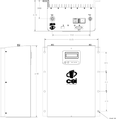
LCD Model Mechanical Drawing
I
O
DISPLAY
Installation
CSI recommends that all BDA installations be coordinated through the local wireless provider.
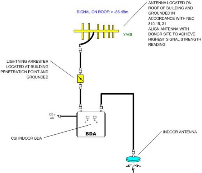
Example: Standard Single Internal Antenna System Design
Optional Accessories
Accessories are available directly from Cellular Specialties, Inc. or any of CSI’s distributors.
• Outside High Gain Yagi Antennas
PCS – model number (CSI-AY/1.85-1.99/10)
SMR and Cellular – model number (CSI-AY/806-960/11) and (CSI-AY/806-960/14)
• Inside Omni directional Antennas
PCS – model number (CSI-AS/1.85-1.99/2)
SMR – model number (CSI-AS/806-866/4)
Dual-Band – model number (CSI-AO/800/2K/3)
• Power Dividers
2:1 - model number (CSI-S2BSC)
3:1 - model number (CSI-S3BSC)
4:1 - model number (CSI-S4BSC)
• Grounding Kit - model number (CSI-GKIT)
• Lightning Arrestor - model number (CSI-CAP)
• Directional Couplers and Cross Band Couplers are also available
Important Installation Notes
• A high degree of isolation must be afforded to prevent any re-generative feedback in the system. Feedback of this nature
causes the amplifier to emit a continuous signal of maximum amplitude and could, in some cases, interfere with normal
operation of the cell site. The minimum required isolation of 80 dB can usually be obtained by mounting the outside antenna
away from the edges of the roof. The use of window mounts or other non-rooftop mountings should be avoided.
• The Installer should refer to the Safety Precautions, in the following section, for proper antenna selection and
installation
Warning! Amplifier Damage will occur if a handset is connected directly to the BDA or the coax that leads to the
BDA.
Important Safety Information
For INDOOR use, an omni-directional antenna with a maximum gain of 3 dBi is authorized for use with
this unit. Inside antennas must be positioned to observe minimum separation of 20 cm. (~ 8 in.) from all
users and bystanders. For the protection of personnel working in the vicinity of inside (downlink)
antennas, the following guidelines for minimum distances between the human body and the antenna must
be observed.
The installation of an INDOOR antenna must be such that, under normal conditions, all personnel cannot
come within 20 cm. (~ 8.0 in.) from any inside antenna. Exceeding this minimum separation will ensure
that the employee or bystander does not receive RF-exposure beyond the maximum permissible
exposure according to section 1.1310 i.e. limits for General Population/Uncontrolled Exposure.
For OUTDOOR use, an omni-directional antenna with a maximum gain of 3 dBi is authorized for use with
this unit. Outside antennas must be positioned to observe minimum separation of 20 cm. (~ 8 in.) from all
users and bystanders. For the protection of personnel working in the vicinity of outside (uplink) antennas,
the following guidelines for minimum distances between the human body and the antenna must be
observed.
The installation of an OUTDOOR antenna must be such that, under normal conditions, all personnel
cannot come within 20 cm. (~ 8.0 in.) from any outside antenna. Exceeding this minimum separation will
ensure that the employee or bystander does not receive RF-exposure beyond the maximum permissible
exposure according to section 1.1310 i.e. limits for General Population/Uncontrolled Exposure.
Performance Adjustment
The menu system can be navigated with five buttons: UP, DOWN, EDIT, SAVE, and
MENU. Feedback is given to the operator through the LCD panel.
Generally speaking, the MENU button is used to switch among various menus available
on the LCD panel without altering the contents of non-volatile memory. The EDIT button is
used to alter values that are present, when possible. The UP and DOWN buttons permit choice
among various options available within a given menu. Once a desired value is found this way, it
can be saved in the 610’s non-volatile memory by pressing SAVE.
Here, then, is a complete list of the menus the operator can expect to encounter during
normal operation and how to navigate them.
Default Menu. This menu is what the LCD panel will show after a power cycle, or after
no button has been pressed for at least an hour and a button is pressed to “wake up” the LCD
panel again. It reveals how much power is currently being carried through the uplink and
downlink channels (dBm), as well as how much automatic gain control is being exerted by the
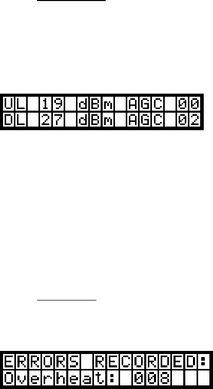
attenuators (dB). A typical display might look like this:
In this instance, through the uplink channel, 19 dBm are being sent; there is no
attenuation. Through the downlink channel, 27 dBm are being sent, and the signal is being
attenuated by 2 dB by the AGC.
It should be noted that under circumstances when the power through a channel is less
than 0 dBm, the display will show “<0” in the location where the reading usually appears.
The UP, DOWN, EDIT, and SAVE buttons have no effect in this menu. However,
pressing the MENU button will advance the LCD panel to the Error Menu.
Error Menu. This menu shows the total of various errors logged by the unit, up to 999 of
each type. If more than 999 errors occur in a particular category, 999 will be displayed. A
typical display might look like this:
There are three errors that the Morph Board currently tracks: Oscillation errors,
which are a total of the number of times the signal has gone into oscillation, combined between
uplink and downlink; Fan Speed errors, which are discrepancies between the speed to which
the fans were set and the speed at which they were found to operate; and Overheat errors,
which are catalogued when the temperature of the board runs too high despite the fans running at
full speed.
Pressing UP and DOWN permits the user to examine the number of errors logged in each
category. Pressing EDIT clears the counters of all errors. Pressing SAVE has no effect. Pressing
MENU sends the user to the Peak Power Menu.
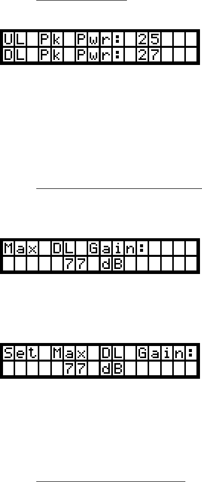
Peak Power Menu. This menu shows the peak power registered by the unit on both the
uplink and the downlink channels. A typical screen for this menu might look like this:
In this instance, the uplink channel has registered a maximum of 25 dBm, and the
downlink channel has registered a maximum of 27 dBm. The maximum power read is stored
until a power cycle or until the user resets the peak power readings, which can be done by
pressing EDIT. Pressing UP, DOWN, or SAVE in this menu has no effect. Pressing MENU
moves the LCD screen to the Maximum Downlink Gain Menu.
Maximum Downlink Gain Menu. This menu shows the maximum gain the unit is
permitted, within its range of acceptable values. Upon entering this menu, the unit defaults to
showing you its current maximum downlink gain.
If the user wants to skip this menu and move on, she may do so by pressing the MENU
button. If, however, she wishes to change the maximum gain the unit will permit, she can press
the EDIT button. The screen will then change to resemble this:
The user can then change the maximum gain of the unit by pressing the UP and DOWN
keys. When the desired maximum gain is shown on the screen, the user can lock this number
into memory by pressing the SAVE key, which will automatically move the unit on to the next
menu: the Maximum Uplink Gain Menu.
Maximum Uplink Gain Menu. This menu behaves in much the same manner as the
Maximum Downlink Gain Menu. If the user changed the maximum downlink gain previously,
this menu will default to showing the same maximum uplink gain. If not, the screen defaults to
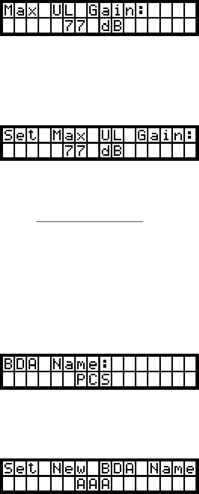
showing the current maximum uplink gain. Upon entering this menu, the screen will resemble
this:
The user can move on to the next menu by pressing the MENU key, or change the value
by pressing EDIT and scrolling to the desired value with the UP and DOWN keys. If the user
chooses to change the maximum uplink gain allowed, the screen will change subtly to resemble
this:
Whether the user moves past this menu or selects a new value and locks it in by pressing
SAVE, the screen will move on to the Network Name menu.
Network Name Menu. This displays the amplifier’s name – which consists of three
characters – on the CAN network, provided the unit is to be plugged into such a network
including a Web Monitor. The characters can be any of the uppercase letters (‘A’ through ‘Z’),
any of the lowercase letters (‘a’ through ‘z’), any of the numerals (‘0’ through ‘9’), or a blank
space, in any order desired.
When the user enters this menu, the screen displays the current name for the amplifier in
a screen like this:
If the user wishes to move on to the next menu, she may do so by pressing the MENU
key. If she wishes to change the amplifier’s name, however, she should press the EDIT key.
Doing so will alter the screen to resemble this:
A blinking cursor shows which character the user is editing. She can change the value of
the given character by pressing UP and DOWN. Once a desired character is reached, it can be
locked in by pressing SAVE, and the cursor will advance to the next character. If moving back a
character is desired, the cursor can be moved to edit the previous character by pressing EDIT.
Once SAVE is pressed while the cursor is on the last character, the new name is locked into non-
volatile memory.
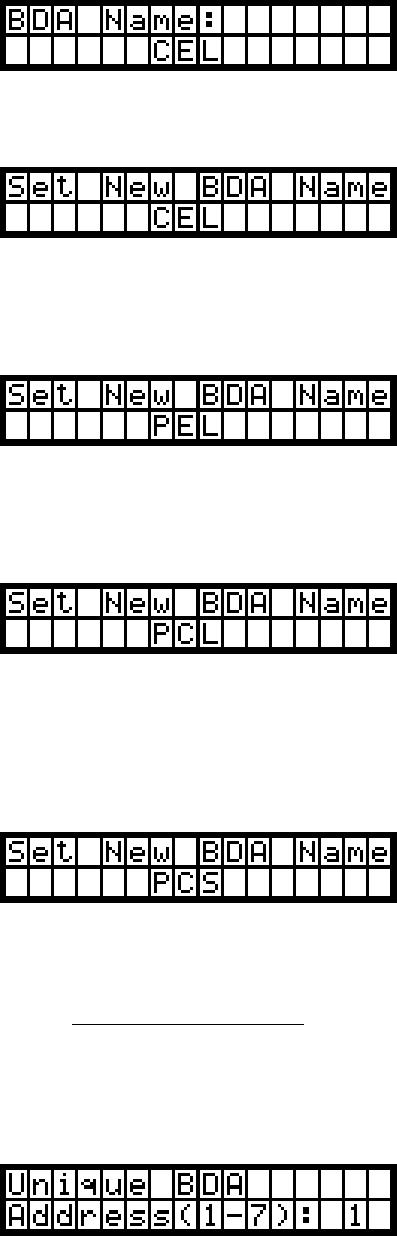
As an example, let’s say the user wants to change the name of the amplifier on the
network from “CEL” to “PCS”. She gets to the menu by pressing MENU until this screen
appears:
Then, to inform the amplifier that she wants to change the name, she presses EDIT, and
this screen appears:
To change ‘A’ to ‘P’, she needs to press the UP key fifteen times. (Alternatively, she
could hold the UP key down until the proper letter appears.) Once she does this, the display
would look like this:
Pressing SAVE would move the blinking cursor from the first letter’s position to the
second letter’s position.
Changing an ‘E’ to a ‘C’ merely requires pressing the DOWN key twice:
Pressing SAVE moves the cursor from the second letter’s position to the third letter’s
position.
Finally, changing an ‘L’ to an ‘S’ requires pressing the UP key seven times, resulting in
this display:
Pressing SAVE at this point would save the new name to memory and move on to the
Network Address Menu.
Network Address Menu. Each amplifier on a CAN network including a Web Monitor
must have a unique address on the network that the Web Monitor can read and write to. This
number can be between one and seven, inclusive. The default address is one.
When the user encounters this menu, the display might look like this:

As usual, the user can move past this menu by pressing MENU, which would return the
user to the Default Menu above. Pressing EDIT, however, changes the screen to resemble this:
The user can then use the UP and DOWN arrows to scroll to a desired address. Pressing
SAVE locks the selected address in non-volatile memory and returns the user to the Default
Menu.
It should be noted that while two amplifiers with the same address on the same network
will not cause a crash, the Web Monitor will only report on the most recent amplifier to send it
information. In addition, commands sent through the Web Monitor to one amplifier will also
affect the other.
Final Note: If the amplifier should become impossible to resuscitate for some reason, and none
of these menu commands are working, the amplifier can be reset to factory defaults by pressing and
holding the UP, DOWN, and MENU keys simultaneously for one second. This is a drastic measure,
however, and should not be implemented unless all other attempts at regaining functionality of the
amplifier have failed.
Troubleshooting
All cables should be carefully checked for “shorts” and “opens”.
The rooftop antenna, if directional, should be checked for proper alignment along the calculated compass heading. Typically,
the directional antenna should be aimed at the same site that your handset uses in the area where the outside antenna is
placed.
If cables and alignment are acceptable, it may be necessary to use a spectrum analyzer to examine the signal environment in
which the BDA is operating. The existence of strong analog signals within the frequency bands can cause the AGC to reduce
the amplifier’s gain particularly on the downlink. In some cases additional filtering might be required to reject these unwanted
signals. In some instances the directional outside antenna can be reoriented, horizontally to place the interfering source in an
antenna pattern “null”. There also may be some cases where the interference from outside signals is so great that they cannot
be filtered or otherwise reduced or eliminated without expensive and possibly prohibitive measures. In these cases it may not
be practical to use the BDA for providing coverage at these sites.
One Year Limited Warranty
Seller warrants that its products are transferred rightfully and with good title; that its products are free from
any lawful security interest or other lien or encumbrance unknown to Buyer; and that for a period of one
year from the date of installation or fifteen months from the date of original shipment, whichever period
expires first, such products will be free from defects in material and workmanship which arise under
proper and normal use and service. Buyer’s exclusive remedy hereunder is limited to Seller’s correction
(either at its plant or at such other place as may be agreed upon between Seller and Buyer) of such
defects by repair or replacement at no cost to Buyer. Buyer shall pay transportation costs in connection
with the return of products to Seller’s plant or designated facility. The provisions of this warranty shall be
applicable with respect to any product that Seller repairs or replaces pursuant to it. SELLER MAKES NO
WARRANTY, EXPRESS OR IMPLIED, OTHER THAN AS SPECIFICALLY STATED ABOVE.
EXPRESSLY EXCLUDED ARE THE IMPLIED WARRANTIES OF MERCHANTABILITY AND FITNESS
FOR PURPOSE. THE FOREGOING SHALL CONSTITUTE ALL OF SELLER’S LIABILITY (EXCEPT AS
TO PATENT INFRINGEMENT) WITH RESPECT TO THE PRODUCTS. IN NO EVENT SHALL SELLER
BE LIABLE FOR SPECIAL, CONSEQUENTIAL OR INCIDENTAL DAMAGES, INSTALLATION COSTS,
LOST REVENUE OR PROFITS, OR ANY OTHER COSTS OF ANY NATURE AS A RESULT OF THE
USE OF PRODUCTS MANUFACTURED BY THE SELLER, WHETHER USED IN ACCORDANCE WITH
INSTRUCTIONS OR NOT. UNDER NO CIRCUMSTANCES SHALL SELLER’S LIABILITY TO BUYER
EXCEED THE ACTUAL SALES PRICE OF THE PRODUCTS PROVIDED HEREUNDER. No
representative is authorized to assume for Seller any other liability in connection with the products.