Westell CSICPBHMG-C4 The Co-Pilot Beacon C4 User Manual D960 1146 002 r006 MANUAL ICEbreaker III indd
Westell, Inc. The Co-Pilot Beacon C4 D960 1146 002 r006 MANUAL ICEbreaker III indd
UserManual.wiki
>
Westell
>
CSICPBHMG C4 User Manual
USER MANUAL
Navigation menu
Upload a User Manual
Namespaces
Wiki Guide
HTML
PDF
Info
Views
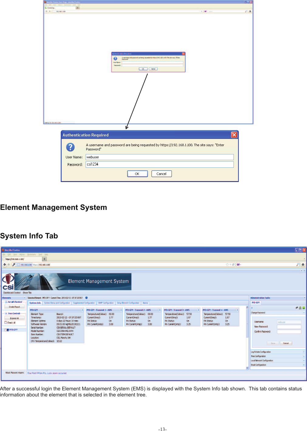
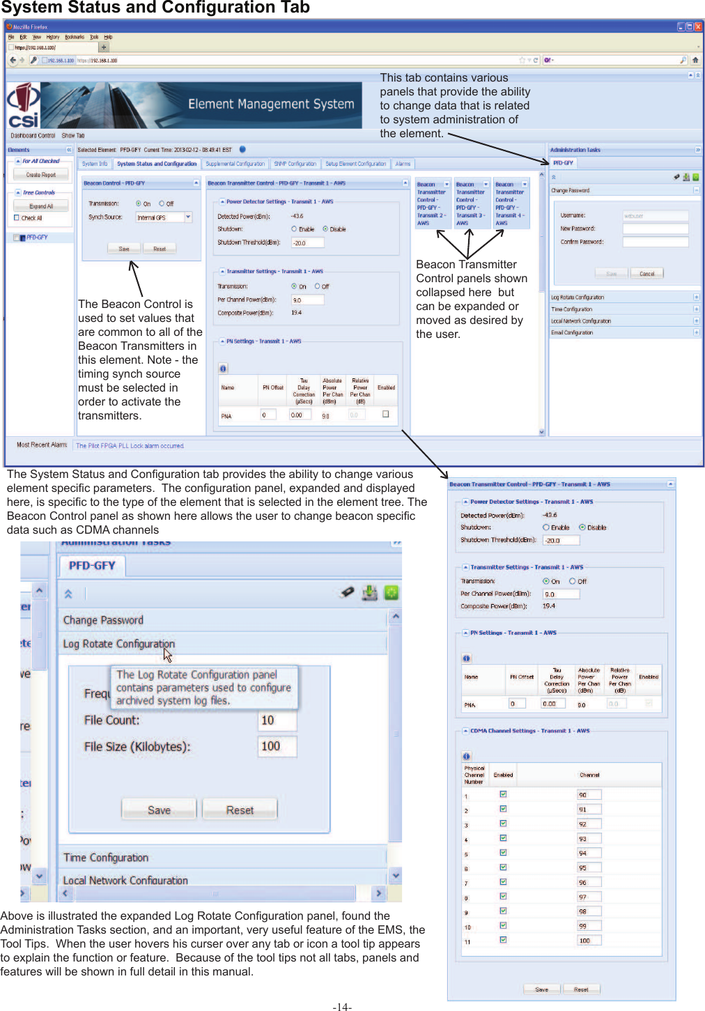
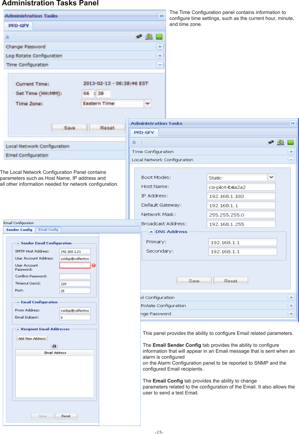
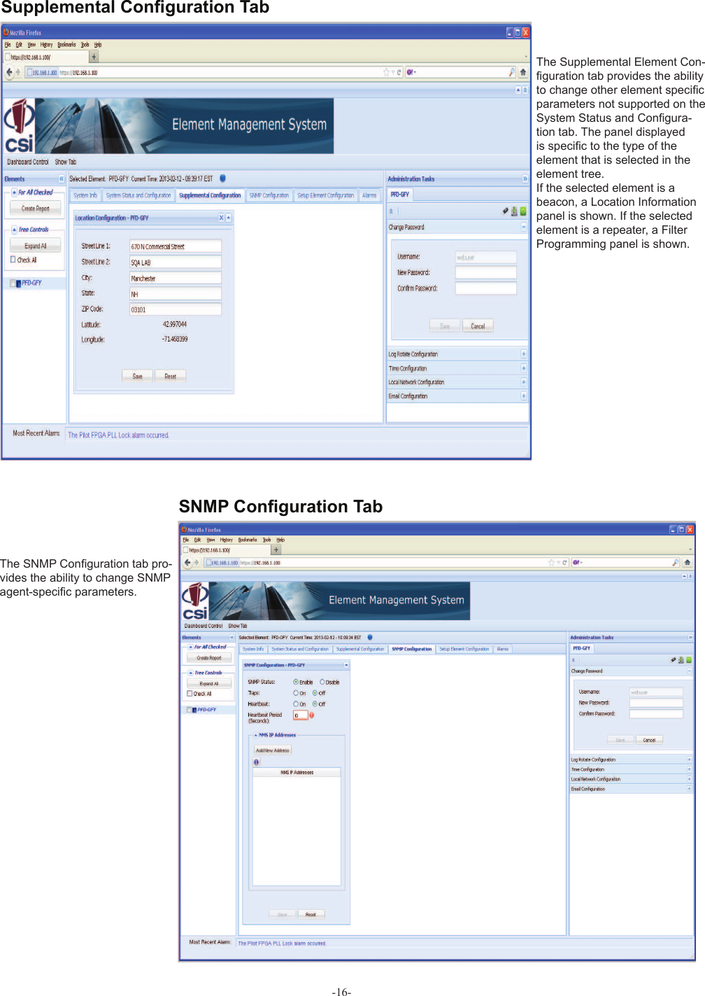
User Manual
Discussion / Help
Navigation