Westell CSICPBHMG-P4 THE CO-PILOT BEACON P4 User Manual D960 1146 002 r006 MANUAL ICEbreaker III indd
Westell, Inc. THE CO-PILOT BEACON P4 D960 1146 002 r006 MANUAL ICEbreaker III indd
Westell >
User Manual
CSI-CPBH-MG-C4, CSI-CPBH-MG-P4,
CSI-CPBH-MG-C2/P2, CSI-CPBH-MG-AW4,
CSI-CPBH-MG-C2/AW2, CSI-CPBH-MG-P2/AW2,
CSI-CPBH-MO-C4, CSI-CPBH-MO-P4,
CSI-CPBH-MO-C2/P2, CSI-CPBH-MO-AW4,
CSI-CPBH-MO-C2/AW2, CSI-CPBH-MO-P2/AW2,
CSI-CPBH-MX-C4, CSI-CPBH-MX-P4,
CSI-CPBH-MX-C2/P2, CSI-CPBH-MX-AW4 ,
CSI-CPBH-MX-C2/AW2, CSI-CPBH-MX-P2/AW2,

Table of Contents
Product Registration Information ........................................................................................................................ 4
Document Purpose / Intended Users ................................................................................................................. 4
Radio and Television Interference ...................................................................................................................... 4
Application .......................................................................................................................................................... 4
Safety Guidelines ............................................................................................................................................... 4
Important Safety Information .............................................................................................................................. 4
Acronyms and Defi nitions ................................................................................................................................... 5
Product Introduction ........................................................................................................................................... 5
Functional Overview ........................................................................................................................................... 6
Electrical Characteristics .................................................................................................................................... 6
Mechanical Specifi cations .................................................................................................................................. 6
AC Power Specifi cations .................................................................................................................................... 6
Environmental Requirements ............................................................................................................................. 6
Mechanical Drawing ......................................................................................................................................... 7
System Set-Up Considerations .......................................................................................................................... 7
Mounting the Co-Pilot Beacon ............................................................................................................................ 7
Typical Co-Pilot/BTS Interconnection with Internal CDMA Timing (MO Series) ................................................. 8
Typical Co-Pilot/Repeater Interconnection with Internal GPS Timing (MG Series) ............................................ 9
Typical Co-Pilot/Repeater Interconnection with External TM-4 (MX Series) .................................................... 10
Optional Accessories .........................................................................................................................................11
Important Installation Notes ...............................................................................................................................11
Powering Up the Unit.........................................................................................................................................11
Local Communication Interface Ports................................................................................................................11
Web based GUI Session .................................................................................................................................. 12
Element Management System ......................................................................................................................... 13
System Info Tab ................................................................................................................................................ 13
System Status and Confi guration Tab .............................................................................................................. 14
Administration Tasks Panel .............................................................................................................................. 15
Supplemental Confi guration Tab ...................................................................................................................... 16
SNMP Confi guration Tab .................................................................................................................................. 16
Alarms Tab ........................................................................................................................................................ 17
Setup Element Confi guration Tab ..................................................................................................................... 17
Special Icons .................................................................................................................................................... 18
Install Software Icon ......................................................................................................................................... 18
Copy Logs Icon................................................................................................................................................. 18
Reboot Icon ...................................................................................................................................................... 18
Collapse/Expand Icon....................................................................................................................................... 19
Alarm Status Icon ............................................................................................................................................. 19
Administration Tasks Collapse/Expand Icon .................................................................................................... 20
Elements Collapse/Expand Icon...................................................................................................................... 21
EIA232 Pin Specifi cations ................................................................................................................................ 22
USB Interface ................................................................................................................................................... 22
Ethernet ............................................................................................................................................................ 22
Monitoring & Alarms ......................................................................................................................................... 22
Text Menu Interface .......................................................................................................................................... 23
Local Access..................................................................................................................................................... 23
User Interface ................................................................................................................................................... 25
Login ................................................................................................................................................................. 25
Main Menu ........................................................................................................................................................ 25
Telnet Session (Remote Access) ...................................................................................................................... 26
Set Parameters Menu....................................................................................................................................... 26
Co-Pilot Beacon Confi guration ......................................................................................................................... 30
Transmitter Confi guration ................................................................................................................................. 30

System Confi guration ....................................................................................................................................... 31
Networking Confi guration ................................................................................................................................. 32
System Commands .......................................................................................................................................... 33
Key Features .................................................................................................................................................... 34
Multiple Beacon Confi guration.......................................................................................................................... 34
Detected RF Power Shutdown ......................................................................................................................... 34
Timing Reference Source ................................................................................................................................. 34
Control Parameter Details ................................................................................................................................ 34
Master Shutdown.............................................................................................................................................. 34
Timing Reference Selection ............................................................................................................................. 34
Channel Frequency Numbers........................................................................................................................... 35
Signal Transmit Enables ................................................................................................................................... 35
PN Offset .......................................................................................................................................................... 36
Tau (Delay Correction)...................................................................................................................................... 36
Co-pilot beacon Per Channel Transmit Power ................................................................................................. 36
Composite Transmit Power .............................................................................................................................. 36
Manual Shutdown ............................................................................................................................................ 36
Auto Shutdown Enable ..................................................................................................................................... 36
Auto Shutdown Threshold ................................................................................................................................ 36
Detected Power ................................................................................................................................................ 36
Additional Tips .................................................................................................................................................. 37
One Year Limited Warranty .............................................................................................................................. 39
Industry Certifi cations/Registration Numbers .................................................................................................. 39
Index ................................................................................................................................................................. 40

-4-
The general safety information in this guideline applies to both operating and service personnel. Specifi c warnings and cautions will be
found in other parts of this manual where they apply, but may not appear in this summary. Failure to comply with these precautions or
specifi c warnings elsewhere in the manual violates safety standards of design, manufacture, and intended use of equipment. Cellular
Specialties, Inc. assumes no liability for the customer’s failure to comply with these requirements:
Grounding
This pilot beacon system is designed to operate from 100-240 VAC and should always
be operated with the ground wire properly connected. Do not remove or otherwise alter the
grounding lug on the power cord.
Explosive Atmospheres
To avoid explosion or fi re, do not operate this product in the presence of fl ammable
gases or fumes.
Lightning Danger
Do not install or make adjustments to this unit during an electrical storm. Use of a suitable lightning arrester, such as CSI’s model
number CSI-CAP, is very strongly recommended.
No User Serviceable Parts Inside
HAZARDOUS VOLTAGES ARE PRESENT WHEN THE COVER IS REMOVED. Opening the chassis will void your warranty. If you
suspect a malfunction with this product, call your dealer or the Cellular Specialties Support Line at: (603) 626-6677, Toll Free (USA)
1-877-844-4274.
The purpose of this document is to provide a step-by-step procedure to help the experienced technician/engineer install and commission
an in-building wireless enhancement pilot beacon system. Following the procedures outlined will minimize risks associated with modifying
a live system and prevent service interruptions. This document assumes the technician/engineer understands the basic principles and
functionality involved with the system. It is geared to the practical concerns of the installer.
Antennas used for the purpose of radiating signals indoors are limited to a maximum gain of 3 dBi. Each antenna must be positioned to
observe minimum separation requirements from all users and bystanders. The following guidelines should be used when considering
separation distances.
INDOOR antennas must be placed such that, under normal conditions, personnel cannot come within 20 cm (~8.0 in.) from any inside
antenna. Adhering to this minimum separation will ensure that the employee or bystander cannot exceed RF exposures beyond the maxi-
mum permissible limit as defi ned by section 1.1310 i.e. limits for General Population/Uncontrolled Exposure.
Document Purpose / Intended Users
Safety Guidelines
Important Safety Information
Product Registration Information
DISCLAIMER: All information and statements contained herein are accurate to the best of the knowledge of Cellular Specialties, Inc. (CSI), but Cellular Specialties makes
no warranty with respect thereto, including without limitation any results that may be obtained from the products described herein or the infringement by such products of
any proprietary rights of any persons. Use or application of such information or statements is at the users sole risk, without any liability on the part of Cellular Specialties,
Inc. Nothing herein shall be construed as licence or recommendation for use, which infringes upon any proprietary rights of any person. Product material and specifi cations
are subject to change without notice. Cellular Specialties’ standard terms of sale and the specifi c terms of any particular sale apply.
The serial number may be found on the label on the bottom panel near the power
connectors. Note this number below. Retain this manual, along with proof of pur-
chase, to serve as a permanent record of your purchase.
MODEL NUMBER SERIAL NUMBER PURCHASE DATE
POINT OF SALE COMPANY
NOTE: This equipment has been tested and found to comply with the limits for a Class A digital device, pursuant to Part 15 of the FCC
rules. These limits are designed to provide reasonable protection against harmful interference when the equipment is operated in a
commercial environment. This equipment generates, uses and can radiate radio frequency energy and, if not installed and used in
accordance with the instruction manual, may cause harmful interference to radio communications. Operation of this equipment in a resi-
dential area is likely to cause harmful interference in which case the user will be required to correct the interference at his own expense.
Changes and Modifi cations not expressly approved by Cellular Specialties, Inc. can void your authority to operate this equipment under
Federal Communications Commission’s rules.
Radio and Television Interference
This device complies with Industry Canada licence-exempt RSS standard(s). Operation is subject to the following two conditions: (1) this
device may not cause interference, and (2) this device must accept any interference, including interference that may cause undesired
operation of the device.
Industry Canada Notice for 850 and 1900MHz Band Models
Cet appareil est conforme aux normes CNR d’Industrie Canada applicables aux appareils radio exempts de licence. Son exploitation est
soumise aux deux conditions suivantes: (1) cet appareil ne doit pas causer d’interférence radioélectrique, et (2) cet appareil doit accepter
toute interférence radioélectrique, incluant les interférences susceptibles d’affecter son fonctionnement de façon indésirable.
Avis de conformité des modèles 850 et 1900 MHz à la réglementation d’Industrie
Canada
-5-
The pilot beacon generator facilitates E911 and other location based services (LBS) for in building and/or DAS based installations of
CDMA2000/1xEV-DO cellular networks. In these situations the normal methods based for location determination, direct reception of
GPS by the mobile station or triangulation using the signals from multiple base stations, do not work. Signals from the GPS system are
suffi ciently weak that even if the mobile station’s GPS receiver might ultimately be able to lock on to the satellites, the acquisition time will
be too long. And since indoor service is typically provided either by a single strong local cell or by using a repeater, there aren’t multiple
signals on which to triangulate while DAS based deployments result in too many signals with indeterminate timing. By placing a pilot
signal at a known PN offset the LBS algorithm can quickly and reliably be made aware that it is within a specifi c building or other location
where normal location determining solutions are ineffective. This information can be used to aid the GPS receiver in acquiring signals if
they are present or be used as a position report directly until more accurate information becomes available.
3GPP2 The standards body comprised of representatives of interested companies that is responsible for the development
and maintenance of the operational standards for the CDMA2000 system. Http://www.3gpp2.org
AGC Automatic Gain Control
CDMA Code Division (or, Domain) Multiple Access: The general term for the technology used in the CDMA2000 system as
well as others. Also a shorthand reference to the CDMA2000 system and its derivatives such as 1xEV-DO
Chip A single element, a ‘1’ or a ‘0’, of the PN Sequence in a CDMA system. The chip rate for the CDMA2000 system is
1.2288 Mchips/second.
CSI Cellular Specialties Incorporated
DAS Distributed Antenna System
ERP Effective Radiated Power
EST Even Second Tick: In the CDMA2000 cellular system all time values are referenced to the start of the even seconds
of time as indicated by GPS.
FCC Federal Communications Commission
FPGA Field Programmable Gate Array
GPS Global Positioning System
IF Intermediate Frequency
LED Light Emitting Diode
NEMA National Electrical Manufacturers Association
PA Power Amplifi er
PN Pseudo random Number: A number chosen by some algorithm that approximates a random process. Can be short
for “PN Sequence”, “PN Number”, or “PN Offset” when discussing the CDMA2000 system.
PN Number In the CDMA2000 system only a subset of the possible PN Offsets are used for base station identifi cation. Each of
these allowed offsets is given a unique number from 0 to 511.
PN Offset In the CDMA2000 System each base station is identifi ed by the offset in time from the EST at which the start of the
Pilot PN Sequence occurs. The offset is specifi ed in terms of number of chips.
PN Sequence A sequence of pseudo random numbers. In the CDMA2000 system several such sequences are used. The one
relevant to ICEBreaker is the Pilot, or Short, sequence which is a 215 element long sequence of ones and zeros.
PPS Pulse per Second: Refers the pulse repetition rate of the timing signal used as a time reference.
RF Radio Frequency
SBC Single Board Computer
Tau Timing Offset or Delay Adjustment: In the CDMA2000 system the timing of the downlink signal is required to be
aligned with the EST as it is transmitted from the antenna. Tau allows the timing of the internal PN Sequence to
be adjusted to compensate for the delays of the base station hardware such that the timing will be correct at the
antenna
USB Universal Serial Bus
Acronyms and Defi nitions
Product Introduction

-6-
Functional Overview
Color Satin Black
Weight 8.4lbs / 3.8kg
Thermal Management Fan Cooled
Surface Coating Powder Coat
Parameter Specifi cation Notes
Pilot Beacon Size
Height 1.73 in.
Width 19.00 in.
Depth 18.02 in.
Mechanical Specifi cations
AC Voltage 100 - 240 VAC External Power Supply
AC Power Frequency 47 - 63 Hz
AC Current 1.7 Amps @ 120 VAC
0.9 Amps @ 230 VAC
Heat Output 500 BTU/Hr
Relative Humidity 5% to 95% Non-condensing
Temperature Range -30° to +48°C
(-22° to +118°F)
AC Power Specifi cations
Parameter Specifi cation Notes
Environmental Requirements
Parameter Specifi cation Notes
Electrical Characteristics
Characteristic Performance Limit
Number of Bands per Beacon 1
CDMA Band Class 0 (Cell), 1 (PCS) and 15 (AWS)
Max # Simultaneous Channels/Beacon 8 (Cell) 11 (PCS and AWS)
Number of Unique PN Offsets/Beacon 1
Composite TX Power +20 dBm
Spurious Emissions Limits < -45 dBc Δf .75 to 1.98 MHZ
< -60 dBc Δf 1.98 to 4.0 MHZ
< -65 dBc Δf 4.0 to 16 MHZ
< -75 dBc Δf > 16 MHZ
Carrier Frequency Accuracy 20 Hz (.2 ppm) Cell Band
40 Hz (.2 ppm) PCS Band
45 Hz (.2 ppm) AWS Band
When locked to GPS
Pilot Timing Jitter < 10 nsec rms, <50 nsec peak
Rho > 0.98
Tau Adjustment Range - 166.7 to + 166.7 µsec (+/- 25.6 CDMA chips)
Tau Adjustment Resolution 20 nsec (one 40th of a CDMA chip)
-7-
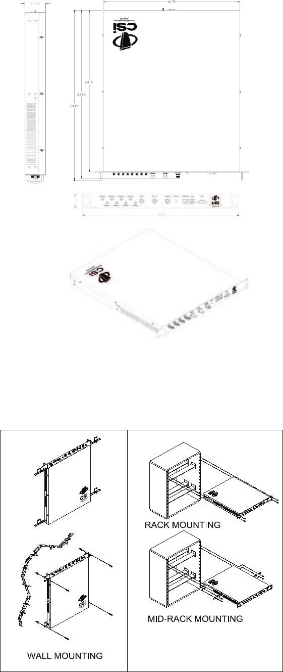
Mechanical Drawing
All cables should be checked for shorts and opens. Also verify that there are no cables with loose or poor connections. It is critical that
the installer contact the service provider before the system is turned on.
The following diagram illustrates the best method for mounting the pilot beacon to a wall in an typical installation.
System Set-Up Considerations
Mounting the Co-Pilot Beacon
-8-
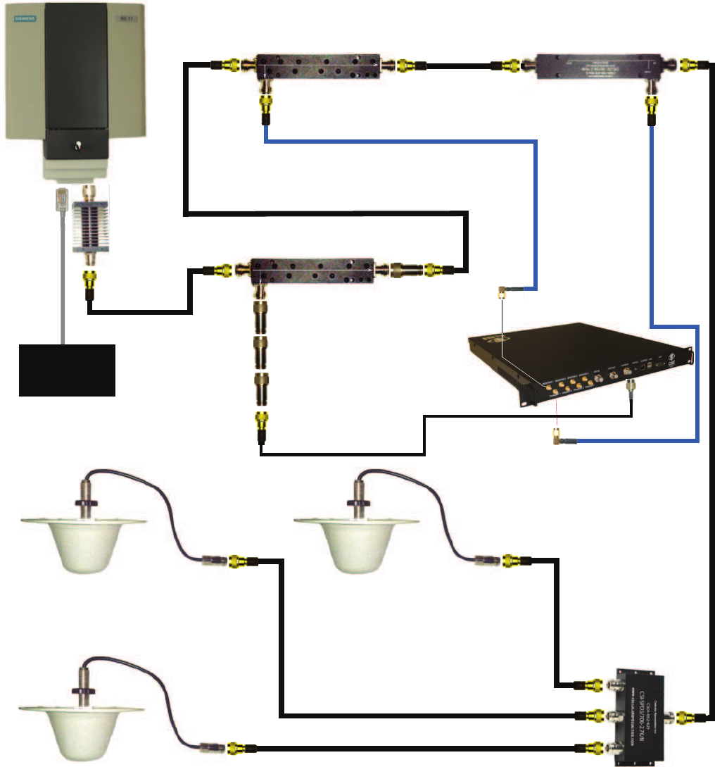
+9.6dBm +9.0dBm
-10.4dBm
Directional Coupler 2 (-20dB)
+8.9dBm +8.3dBm
-15.1dBm
Directional Coupler 3 (-20dB)
+20.0dBm
BTS
Co-Pilot Beacon (MO Series)
Equipped with Praecis II CDMA
Timing Module
-10.5dBm
+20.0dBm
-0.1dBm
-15.2dBm
-50.2dBm
DAS
RF
Jumper
NM-NM
RF Jumper
NM-NM
IN OUT
-20dB
RF Jumper
NM-SMAM
RF
Jumper
NM-SMAM
-15.8dBm
-15.9dBm
IN
OUT -20dB
See note 4
Network
IN OUT
-30dB
Directional Coupler 1 (-30dB)
RF Jumper
NM-NM
+19.9dBm
20dB Fixed
Attenuator
RF Jumper
NM-TNCM
-10.1dBm
-60.1dBm
+9.7dBm
-16.0dBm
+19.9dBm
-68.5dBm
-16.2dBm
-138.5dBm
-138.6dBm
20dB Fixed
Attenuator
See note 6
Notes:
1. It is recommended that all unused ports be terminated at 50 ohms. When properly terminated, the possibility of false shutdown is minimized because high reflections at open
ports are eliminated.
2. The values shown in this drawing are only an example. Power levels encountered at each installation may require different coupling, pads, and threshold values.
3. This example assumes a BTS with power at the output set to 40dBm, co-pilot beacon output set at 20dBm.
4. Threshold Power Level in this example is set to -20dBm (Approximately 10dB below the power level at the monitor input.)
5. DAS Power Detection and Shutdown functionality:
- If RF Detector measures Input power lower than the Threshold Power Level set by
the user, then the Co-Pilot Beacon’s RF power output will be shut down.
- An alarm occurs. (Delay approximately one second on-off and one second off-on.
6. Co-pilot beacon signal reflecting back to the input of the CDMA timing source must never be allowed to exceed -124dBm.
-60.2dBm
10dB Fixed
Attenuator
10dB Fixed
Attenuator
20dB
Fixed
Attenuator
Typical Co-Pilot/BTS Interconnection with Internal CDMA Timing (MO Series)
-9-
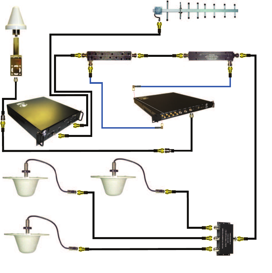
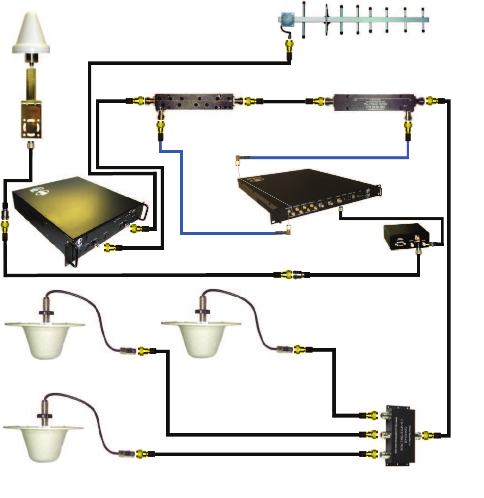
Typical Co-Pilot/Repeater Interconnection with Internal GPS Timing (MG Series)
9.9dBm +9.3dBm
-10.1dBm
Directional Coupler 1 +9.2dBm +8.6dBm
-15.1dBm
Directional Coupler 2
+10.0dBm
Donor
-75.0dBm
-10.2dBm
-0.1dBm
-15.2dBm
-50.2dBm
DAS
IN OUT
-20dB
+19.9dBm
-15.8dBm
-15.9dBm
IN
OUT -20dB
See note 4
GPS Antenna
Antenna
Bracket
RF
Jumper
NF-TNCM
RF Jumper
NM-SMAM
RF Jumper
NM-SMAM
+20.0dBm
RF Jumper
NF-TNCM
RF
Jumper
NM-NM
RF
Jumper
NM-NM
Co-Pilot Beacon (MG Series)
Equipped with Trimble Embedded
GPS Timing Receiver
Notes:
1. It is recommended that all unused ports be terminated at 50 ohms. When properly terminated, the possibility of false shutdown is minimized because
high reflections at open ports are eliminated.
2. The values shown in this drawing are only an example. Power levels encountered at each installation may require different coupling, pads, and threshold
values.
3. This example assumes -75dBm input at the repeater, repeater gain set to 85dB, co-pilot beacon output set at 20dBm and use of 20dB directional
couplers with 20dB coupling, and assumed 15dB worst case directivity.
4. Threshold Power Level in this example is set to -20dBm (Approximately 10dB below the power level at the monitor input.)
5. DAS Power Detection and Shutdown functionality:
- If RF Detector measures Input power lower than the Threshold Power Level set by the user, then the Co-Pilot Beacon’s
RF power output will be shut down.
- An alarm occurs. (Delay approximately one second on-off and one second off-on.
Repeater
-10-
+9.9dBm +9.3dBm
-10.1dBm
Directional Coupler 1 +9.2dBm +8.6dBm
-15.1dBm
Directional Coupler 2
+10.0dBm
Donor
-75.0dBm
-10.2dBm
-0.1dBm
-15.2dBm
-50.2dBm
DAS
IN OUT
-20dB
+19.9dBm
-15.8dBm
-15.9dBm
IN
OUT -20dB
See note 4
GPS Antenna
Antenna
Bracket
RF
Jumper
NF-TNCM
RF Jumper
NM-SMAM
RF Jumper
NM-SMAM
+20.0dBm
RF Jumper
NF-TNCM
RF Jumper
NM-NM
RF
Jumper
NM-NM
Co-Pilot Beacon (MX Series)
Notes:
1. It is recommended that all unused ports be terminated at 50 ohms. When properly terminated, the possibility of false shutdown is minimized because high
reflections at open ports are eliminated.
2. The values shown in this drawing are only an example. Power levels encountered at each installation may require different coupling, pads, and threshold values.
3. This example assumes -75dBm input at the repeater, repeater gain set to 85dB, co-pilot beacon output set at 20dBm and use of 20dB directional couplers with
20dB coupling, and assumed 15dB worst case directivity.
4. Threshold Power Level in this example is set to -20dBm (Approximately 10dB below the power level at the monitor input.)
5. DAS Power Detection and Shutdown functionality:
- If RF Detector measures Input power lower than the Threshold Power Level set by
the user, then the Co-Pilot Beacon’s RF power output will be shut down.
- An alarm occurs. (Delay approximately one second on-off and one second off-on.
Repeater
RF Jumper
BNCM-TNCM
TM-4
Typical Co-Pilot/Repeater Interconnection with External TM-4 (MX Series)

-11-
During Power up, the pilot beacon will require approximately three minutes for the internal computer to boot up. During this time the LED
on the front panel may light and go out several times. When boot is complete and no alarm conditions exist, the LED indicators will be
illuminated green.
Do not unplug the unit while it is in the boot up process!
Powering Up the Unit
To allow monitoring and control, the pilot beacon is equipped with four ports that provide external communication access (1 Ethernet
CAT-5, 1 DB-9 serial, and 2 USB). The Ethernet, CAT-5 port is provided as a primary communications port to the PC. One serial inter-
face, COM 1, can provide communications to local PC. The USB interface provides a means to download fi les from a memory device.
The DB-9 pin assignments of COM 1 conform to the standard Electronic Industries Association (EIA232) specifi cation. A diagram of the
pin descriptions is provided on the next page for reference.
Connecting a null modem cable to the COM 1 port and using a terminal emulation program with a PC will allow communication to the
control processor’s Text Menu Interface (TMI) for trouble shooting and advanced diagnostics. Call CSI technical support for assistance if
you need to access these advanced features or for further information.
The proprietary external GPS receiver connection is made at the port labeled “GPS”. Do not connect other devices or non-straight-
through serial extension cables to this port. Place the GPS receiver in a location with the best view of the unobstructed sky that is
possible, although a 100% open view of the sky is not necessary to achieve a stable time lock.
Local Communication Interface Ports
• The installer should refer to the Safety Guidelines section and the Important Safety Information section for proper antenna selection and
installation. To avoid serious injury or death and damage to the pilot beacon, do not install server antennas near overhead power lines or
high power components. Allow enough distance so that if antennas should fall they will not come in contact with those components.
• Close proximity to the server antennas with the pilot beacon in operation may expose the user or installer to RF fi elds that exceed FCC
limits for human exposure.
WARNING! PILOT BEACON AND/OR HANDSET DAMAGE MAY OCCUR IF A HANDSET IS CONNECTED DIRECTLY TO THE
PILOT BEACON OR THE COAX THAT LEADS TO THE PILOT BEACON.
Important Installation Notes
A complete line of accessories is available from Cellular Specialties, Inc. Check with your CSI distributor for any additional items needed.
Below are just a few examples suitable for most in-building needs.
• Directional Couplers
6dB - model number: CSI-DC6/700-2.7K/N
10dB - model number: CSI-DC10/700-2.7K/N
15dB - model number: CSI-DC15/700-2.7K/N
20dB - model number: CSI-DC20/700-2.7K/N
30dB - model number: CSI-DC30/700-2.7K/N
Battery backup, 4 hr Single band
2 hour dual band - model number: CS48-985-601
• Power Dividers
2:1 - model number: CSI-SPD2/700-2.7K/N
3:1 - model number: CSI-SPD3/700-2.7K/N
4:1 - model number: CSI-SPD4/700-2.7K/N
• Grounding Kit - model number: CSI-GKIT
• Lightning Arrestor - model number: CSI-CAP
• Inside Omnidirectional Antenna
Quad-band - model number: CSI-AO/700/2.7K/3
Optional Accessories
Warning: Power supply cable connector is keyed for proper orientation and is designed to lock into place.
Keyed for proper
alignment, do not
force connector
into place.
-12-
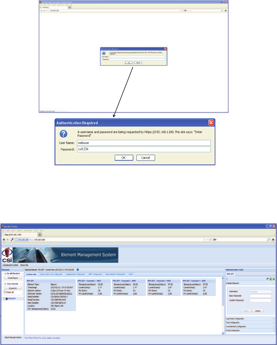
Primary access to the unit is gained using a LAN connection and a web browser program such as Firefox by Mozilla, or Internet Explorer
from Microsoft. The beacon ships with the default IP address of 192.168.1.100, but it can be changed later if required.
Connecting directly to the unit from a laptop or PC with a crossed CAT-5E cable or over a LAN the user types the IP address of the unit
into the browser address line to connect. Most users will need to update the TCP/IP settings on their computer to enable connection to a
host that has a static IP. Select “Use the following IP Address” and enter the IP Address as follows: 192.168.1.x, where “x” = any number
from 2 to 254 inclusive other than 100. The subnet mask is 255.255.255.0. Questions pertaining to these settings should be referred to
the user’s IT department or you may refer to the Additional Tips section at the end of this manual. When connection is made the user will
be prompted for a user name and password. For the purpose of the GUI session, the default user name is webuser and the password
is csi1234. This can also be changed as required. Internet access is not required to use the GUI. If you are connecting using a laptop,
verify that your Ethernet port is powered. Some laptops will not allow Ethernet connection when on battery power. If this is the case with
the laptop you are using you will need to plug it in or update the power settings. °See below for detail with regard to cables and connect-
ing to your PC.
Web based GUI Session
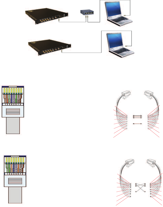
The diagram below shows the normal use of Crossed and Straight cables.
Straight Cable
Crossed Cable
Straight Cable
Straight Cable
Crossed Cable
PC
PC
Hub or
Switch
Co-Pilot
Beacon
Co-Pilot
Beacon
Pin # Signal AT&T 258A
1 Transmit+ White/Orange
2 Transmit- Orange/White
or Orange
3 Receive+ White/Green
4 N/A Blue/White
or Blue
5 N/A White/Blue
6 Receive- Green/White
or Green
7 N/A White/Brown
8 N/A Brown/White
or Brown
Pin # Signal AT&T 258A
1 Receive+ White/Orange
2 Receive- Orange/White
or Orange
3 Transmit+ White/Green
4 N/A Blue/White
or Blue
5 N/A White/Blue
6 Transmit- Green/White
or Green
7 N/A White/Brown
8 N/A Brown/White
or Brown
A B
1
2
3
4
5
6
7
8
8
7
6
5
4
3
2
1
1
2
3
4
5
6
7
8
8
7
6
5
4
3
2
1
-13-
After a successful login the Element Management System (EMS) is displayed with the System Info tab shown. This tab contains status
information about the element that is selected in the element tree.
Element Management System
System Info Tab
-14-
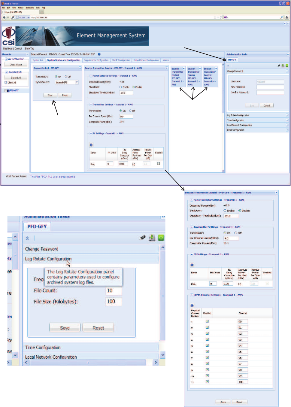
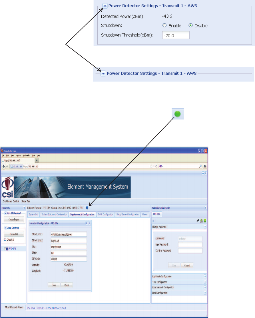
The System Status and Confi guration tab provides the ability to change various
element specifi c parameters. The confi guration panel, expanded and displayed
here, is specifi c to the type of the element that is selected in the element tree. The
Beacon Control panel as shown here allows the user to change beacon specifi c
data such as CDMA channels
Beacon Transmitter
Control panels shown
collapsed here but
can be expanded or
moved as desired by
the user.
The Beacon Control is
used to set values that
are common to all of the
Beacon Transmitters in
this element. Note - the
timing synch source
must be selected in
order to activate the
transmitters.
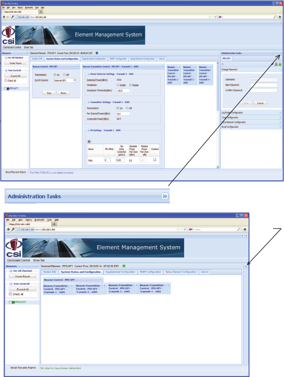
This tab contains various
panels that provide the ability
to change data that is related
to system administration of
the element.
Above is illustrated the expanded Log Rotate Confi guration panel, found the
Administration Tasks section, and an important, very useful feature of the EMS, the
Tool Tips. When the user hovers his curser over any tab or icon a tool tip appears
to explain the function or feature. Because of the tool tips not all tabs, panels and
features will be shown in full detail in this manual.
System Status and Confi guration Tab
-15-
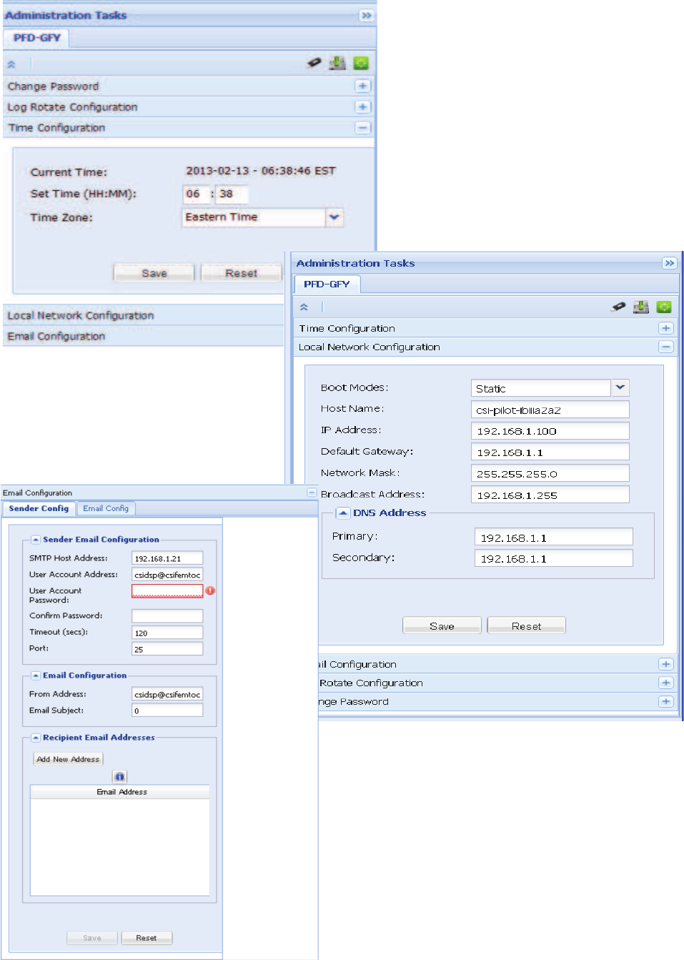
The Time Confi guration panel contains information to
confi gure time settings, such as the current hour, minute,
and time zone.
The Local Network Confi guration Panel contains
parameters such as Host Name, IP address and
all other information needed for network confi guration.
This panel provides the ability to confi gure Email related parameters.
The Email Sender Confi g tab provides the ability to confi gure
information that will appear in an Email message that is sent when an
alarm is confi gured
on the Alarm Confi guration panel to be reported to SNMP and the
confi gured Email recipients.
The Email Confi g tab provides the ability to change
parameters related to the confi guration of the Email. It also allows the
user to send a test Email.
Administration Tasks Panel
-16-
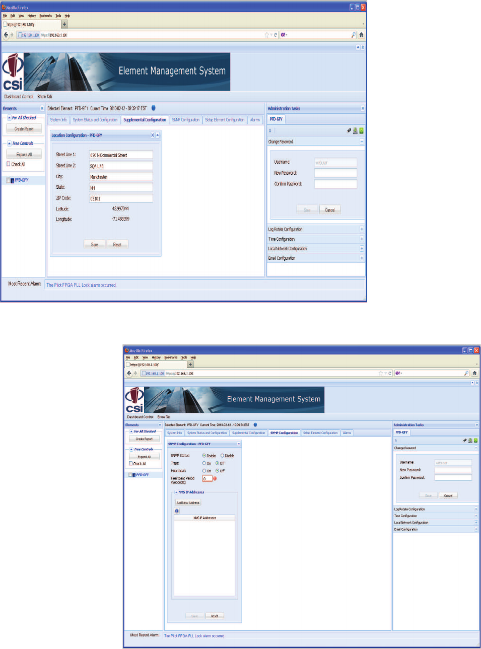
The Supplemental Element Con-
fi guration tab provides the ability
to change other element specifi c
parameters not supported on the
System Status and Confi gura-
tion tab. The panel displayed
is specifi c to the type of the
element that is selected in the
element tree.
If the selected element is a
beacon, a Location Information
panel is shown. If the selected
element is a repeater, a Filter
Programming panel is shown.
The SNMP Confi guration tab pro-
vides the ability to change SNMP
agent-specifi c parameters.
Supplemental Confi guration Tab
SNMP Confi guration Tab
-17-
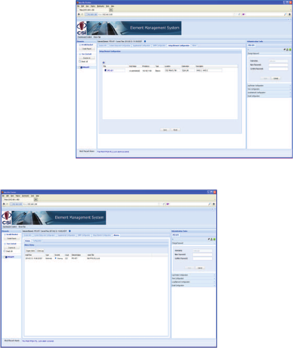
The Setup Element Confi guration
panel allows the user to update
identifi cation information
about the elements in the net-
work.
The Alarms tab shows panels
that allow the user to view the
alarms on the element and to
confi gure alarms for reporting to
SNMP and the confi gured Email
recipients.
Status panel shows alarms that
exist on the element and their
corresponding corrective actions.
Hover over the Alarm Title to
see a description and corrective
action for any alarms that exist
on the element. Alarms can be
cleared and a test alarm can be
triggered on this panel.
Confi guration panel provides
the ability to enable and disable
the reporting of a particular alarm
to SNMP and the confi gured
Email recipients.
Setup Element Confi guration Tab
Alarms Tab
-18-
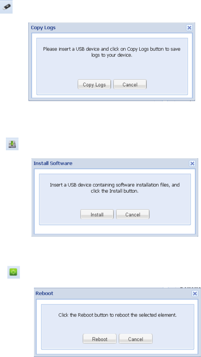
Special Icons
Copy Logs Icon Clicking on the copy logs button will bring the user to the copy logs dialog box shown below.
This feature will allow the user to copy the alarm logs to a thumb drive for archiving and
analysis.
Install Software Icon The Install Software button will bring the user to the Install Software dialog box shown below.
This feature will allow the user to copy and install new software to the co-pilot beacon from a
thumb drive.
Reboot Icon The Install Software button will bring the user to the Install Software dialog box shown below.
This feature will allow the user to copy and install new software to the co-pilot beacon from a
thumb drive.
-19-
To collapse or expand any panel
the user can click on this icon.
Collapse/Expand Icon
Alarm Status Icon This icon indicates alarm status. When
there are no alarms this icon is green.
Major alarms will cause it to turn red.
Clicking the icon will open the Alarms
Tab so that the user can review the
alarms.
-20-
Administration Tasks
Collapse/Expand Icon
To restore the
panel the user
can click on
this icon.
-21-
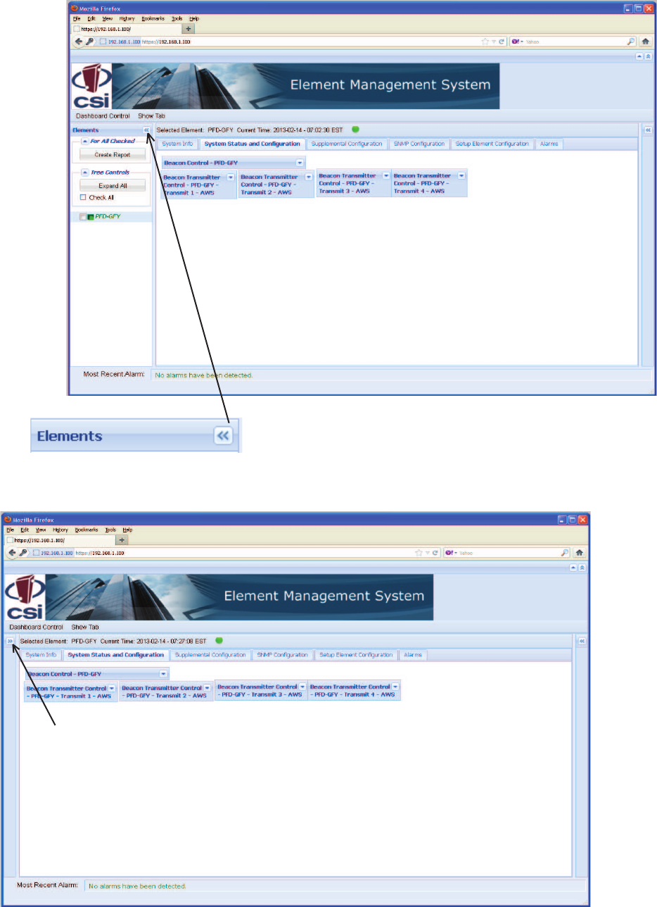
Elements Collapse/Expand Icon
To restore the panel the user can click on this icon.
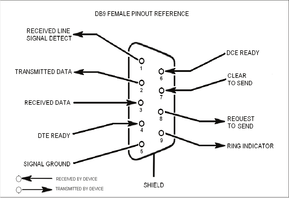
EIA232 Pin Specifi cations
The diagram above is for reference only, it’s intended to provide a quick source for pinout information in the event it should be neces-
sary to adapt your serial cable because of an unusual connector confi guration. In the vast majority of cases this information will not be
needed.
There are no physical connections provided to exclusively and specifi cally communicate system or alarm status. Information with regard
to system or alarm status is provided by the GUI accessible via the communication ports described earlier.
The Universal Serial Bus (USB) interface conforms to Intel’s Universal Host Controller Interface (UHCI) version 1.1 dated March 21,
1996. This interface will support data transfer rates up to 12 Mbps and can be used for software updates.
The Ethernet AUI conforms to IEEE 802.3 and is capable of supporting 10/100 Mbps communications speeds. This port is used to pro-
vide access to the UI.
USB Interface
Ethernet
Monitoring & Alarms
-22-
Text Menu Interface
Figure 1
Figure 2
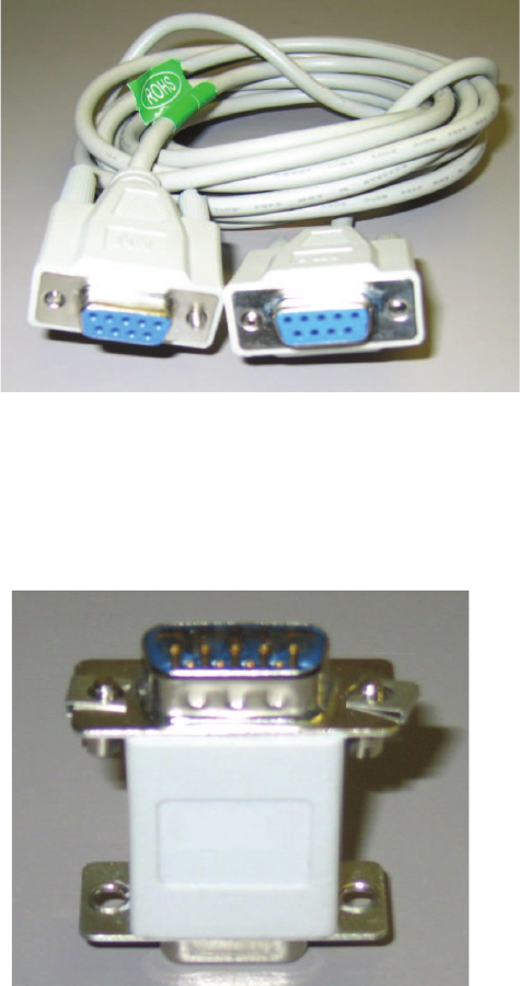
Local access to the repeater Text Menu Interface, also known as the TMI or console interface, is made by connecting a Female to
Female serial cable, (not supplied with the repeater or this software update), as shown in fi gure 1, from the serial connector of the laptop
to either of the serial ports on the bottom end panel of the repeater. These connectors are labeled COM 1 and COM 2. In some cases, a
gender adapter may be needed if the computer serial port or cable connectors are not the same as shown in fi gure 1. Figure 2 shows a
connector gender adapter. In some cases when a newer laptop is used that does not have a serial port, a USB serial adapter may be re-
quired. A Tripp-Lite, model: USA-19HS is recommended. The USB media you’ve used for this upgrade should be inserted in an available
USB port before starting the upgrade process.
Local Access
-23-
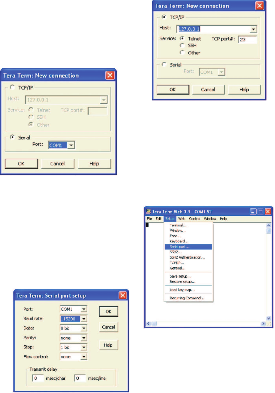
Pressing “OK” will open up a blank dialog screen. Go to the setup
dropdown menu and select Serial port to make changes to the serial
port setup.
Confi gure the terminal program for the correct COM port, in this
case COM 1 and 115200 baud rate as shown below.
Many terminal emulation programs will work if properly confi gured. In the
following description, “TeraTerm” is used to establish the TMI session.
This program is readily available via the Internet and is free from Ayera
Technologies at: http://www.ayera.com/teraterm/
TeraTerm Pro Web works on Windows 95/98, 2000, XP. Here is the latest
TeraTerm Pro Web release: Version 3.1.3, October 8, 2002. ttpro313.zip
When the program is started, the following screen is displayed.
Select the Serial radio button and press OK as shown below.
Note: It may be necessary, in the System Properties section of the control panel; using Device
Manager to determine what COM port your computer uses for the communications port. In this case it is COM 1. This is not to be con-
fused with the serial port on the bottom panel of the repeater labeled COM 1.
-24-
User Interface
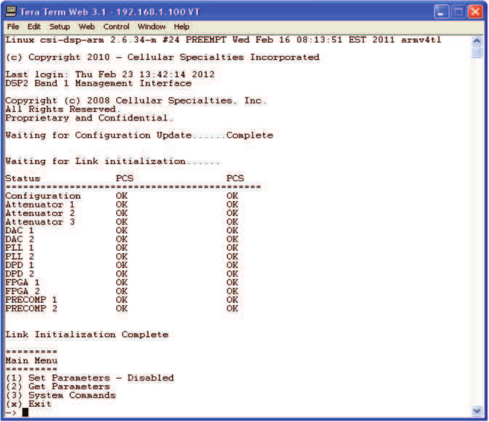
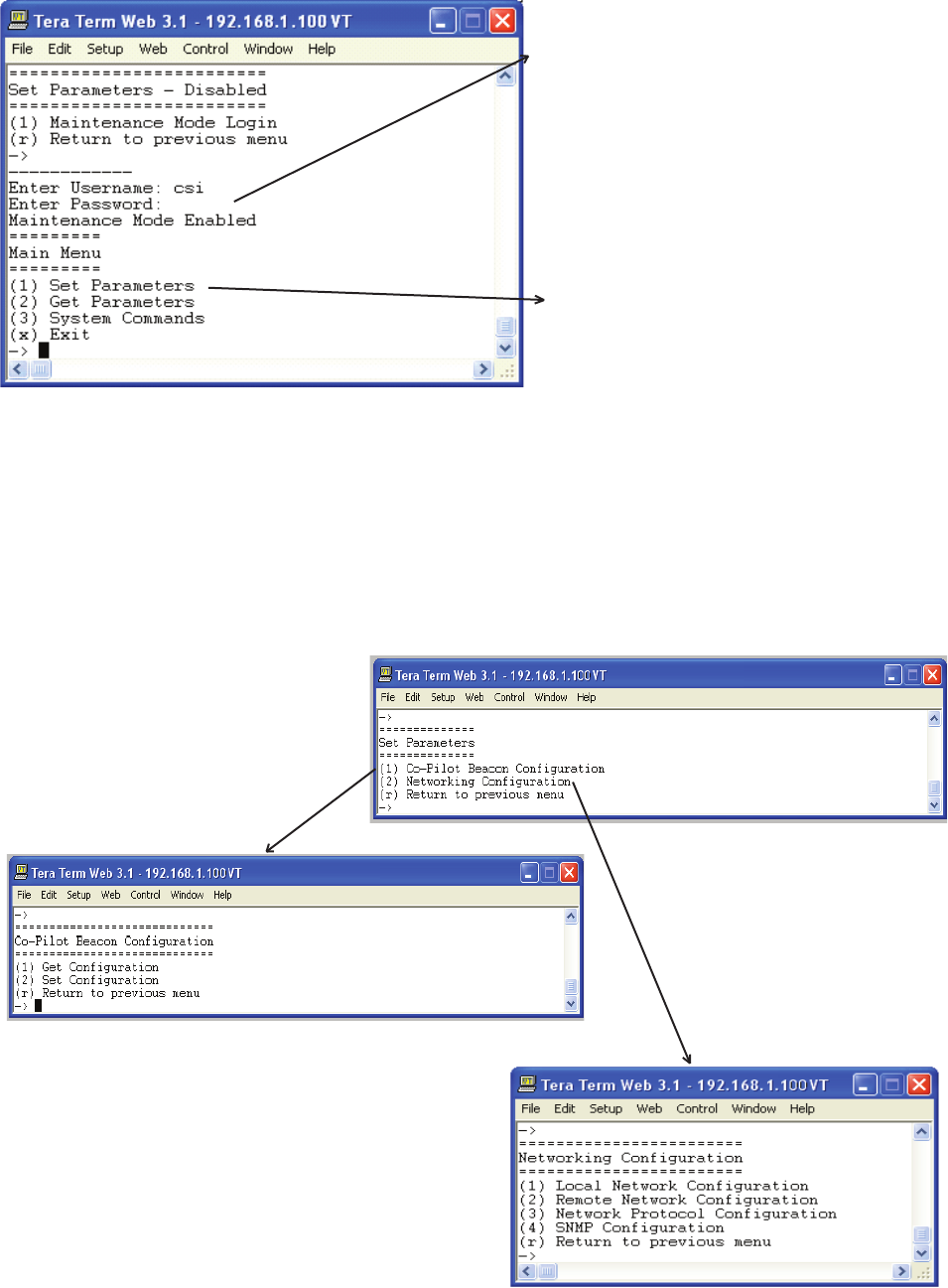
Upon successful login the unit displays the main menu.
Main Menu
Once the unit has completed its boot up and link initialization phases it will display the login prompt. The username is “bandone” for the
fi rst two beacons and “bandtwo” for the second two beacons. The password is “csi1234”.
Login
-25-
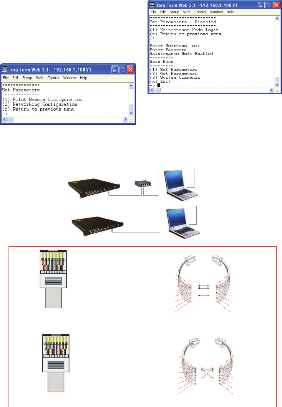
The diagram below shows the normal use of Crossed and Straight cables.
Straight Cable
Crossed Cable
Telnet Session (Remote Access)
Set Parameters Menu
Once the maintenance mode login is performed successfully the
main menu will be displayed again but without the “(Disabled)”
qualifi er on the “Set Parameters” choice.
When “Set Parameters” is fi rst selected the unit will ask for
the maintenance mode login. (The default username for the
maintenance mode is “csi” and the password is “csi1234”.)
Straight Cable
Straight Cable
Crossed Cable
PC
PC
Hub or
Switch
Co-Pilot
Beacon
Co-Pilot
Beacon
Pin # Signal AT&T 258A
1 Transmit+ White/Orange
2 Transmit- Orange/White
or Orange
3 Receive+ White/Green
4 N/A Blue/White
or Blue
5 N/A White/Blue
6 Receive- Green/White
or Green
7 N/A White/Brown
8 N/A Brown/White
or Brown
Pin # Signal AT&T 258A
1 Receive+ White/Orange
2 Receive- Orange/White
or Orange
3 Transmit+ White/Green
4 N/A Blue/White
or Blue
5 N/A White/Blue
6 Transmit- Green/White
or Green
7 N/A White/Brown
8 N/A Brown/White
or Brown
A B
1
2
3
4
5
6
7
8
8
7
6
5
4
3
2
1
1
2
3
4
5
6
7
8
8
7
6
5
4
3
2
1
-26-
Remote access to the repeater may be gained through a LAN connection and a terminal emulation program for TCP/IP. As with the se-
rial connection, many terminal emulation programs will work, if properly confi gured. In the following description, “TeraTerm” is used to
establish the Telnet session. Also, it will be required that the network confi guration of the computer and the repeater being controlled be
set up with the same Sub Net and Sub Net Mask in order to establish a link. In other words, the IP addresses of both the computer used
and the repeater must use the same group of IP address number sets. For example, the repeater ships with the default IP address of
192.168.1.100 and a Sub Net Mask of 255.255.255.0. In order to connect, the computer to be used for the link would normally need an IP
address of something like 192.168.1.12 with a Sub Net Mask of 255.255.255.0, the same Sub Net Mask as the repeater. In this example
note: the last digit of the IP address may be any number except 1,100 and 255. Confi guring your PC is normally fairly straight forward
but it does vary somewhat with the operating system involved. If you require assistance, contact your IT department and they will be able
to set up your PC for you or you may review the Additional Tips Section at the end of the manual.
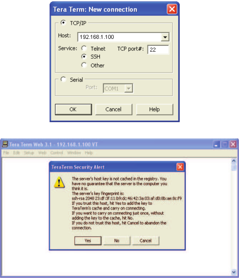
When the TeraTerm program is started, the following screen is displayed. Change the default host IP address to the IP address of the
repeater to be controlled. In the case of a new install, the default address is 192.168.1.100 and has been assigned at the factory. Select
the service Telnet. The TCP Port must be 23.
Pressing the “OK” button will display the security alert shown below.
Click the yes button and the fi rst SSH2 Authentication Challenge screen is displayed. The user then types the username in the space
provided. In multi beacon units, each set of beacons are changed independently and requires an independent login. To make changes
default user names are “bandone” for the fi rst two beacons and “bandtwo” for the second two beacons respectively .
-27-
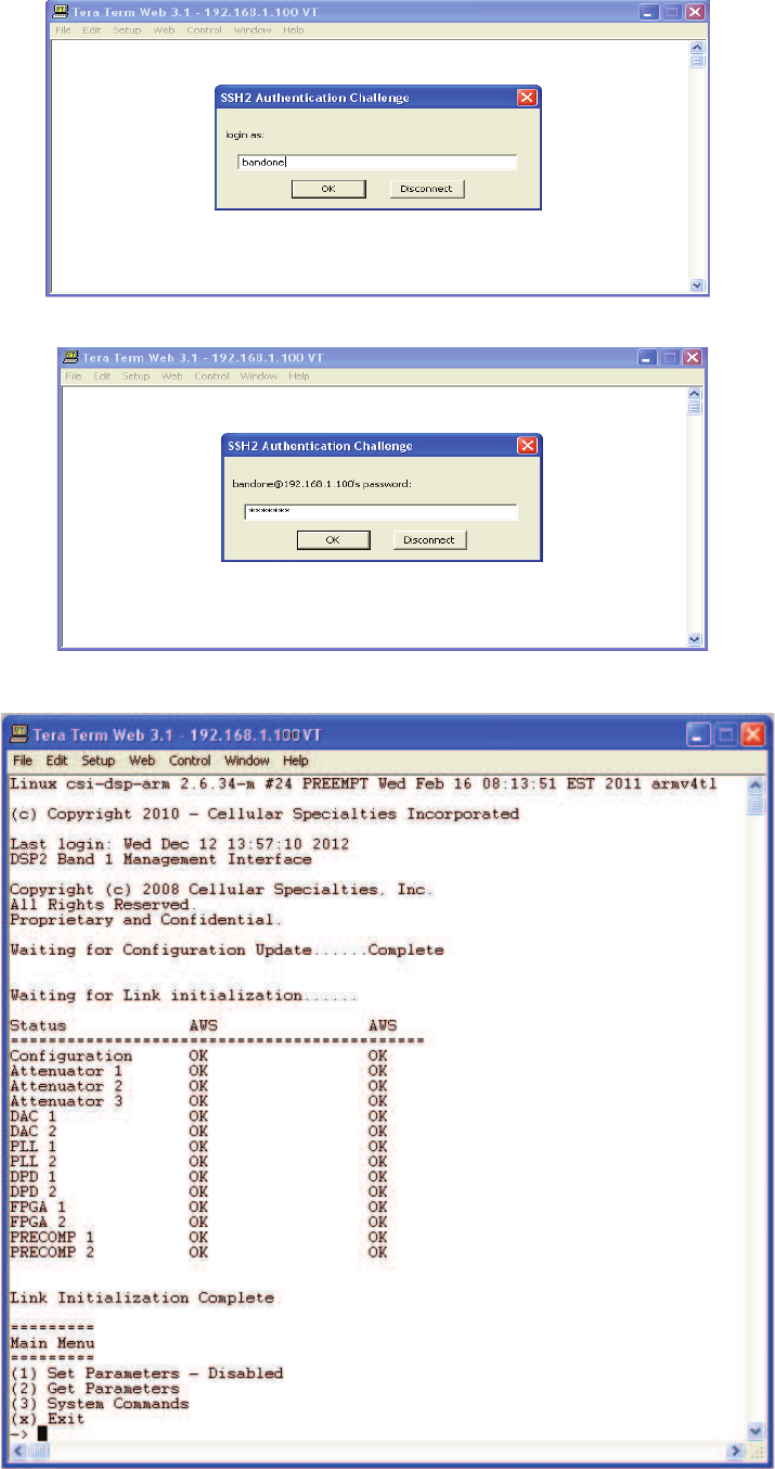
In the fi eld provided, type the user name for the beacon to be changed. The default password is “csi1234” for all beacons. After typing
the password press OK and the main menu will be displayed as shown next.
Press OK after entering the user name and the second SSH2 Authentication Challenge will be displayed.
-27-
Set Parameters Menu
Once the maintenance mode login is performed
successfully the main menu will be displayed again
but without the “(Disabled)” qualifi er on the “Set
Parameters” choice.
When “Set Parameters” is fi rst selected the unit will ask
for the maintenance mode login. (The default username
for the maintenance mode is “csi” and the password is
“csi1234”.)
Selection of option 1 will display the Co-Pilot Confi guration Menu. Option 2 displays the Networking Confi guration Menu. These menus
allow the user to choose set up options menus that are fairly self explanatory but are displayed in the following pages for clarifi cation.
-29-
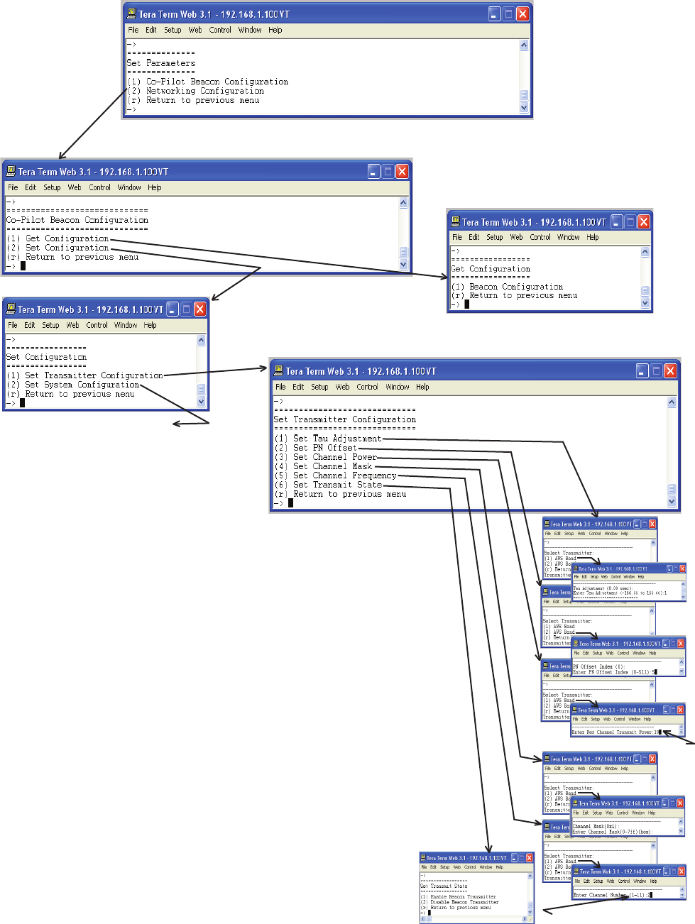
Co-Pilot Beacon Confi guration
Selecting option 1 will display the
current beacon confi guration but does
not allow the user to change any setting.
Acceptable power range is 0-20
Selection of option 2 allows for the
setting of Transmitter and System
Confi guration.
* Note Top line parenthesis shows
current value. Bottom line shows
range of acceptable values.
*
*
*
Acceptable channel range
See next page for the Set System
Confi guration selections.
When selecting each option on
the Set Transmitter Confi guration
menu the user is presented with
the Select Transmitter menu
fi rst to allow for the selection of
transmitter for this section of the
unit.
Transmitter Confi guration
-30-
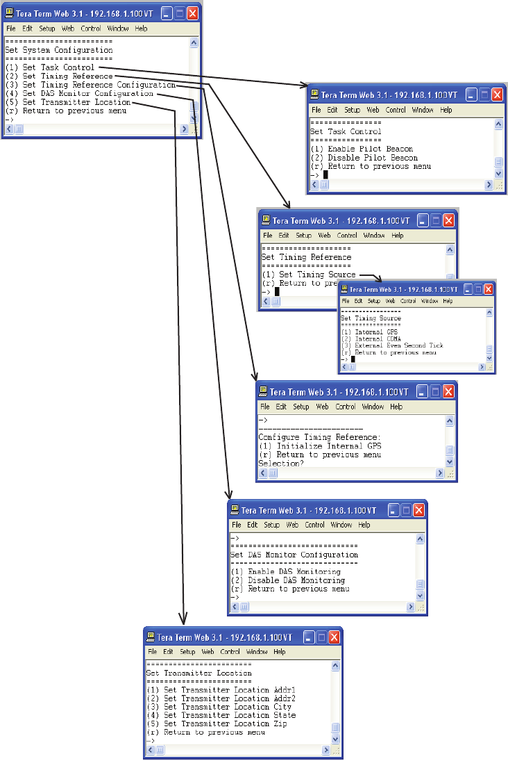
System Confi guration
-31-
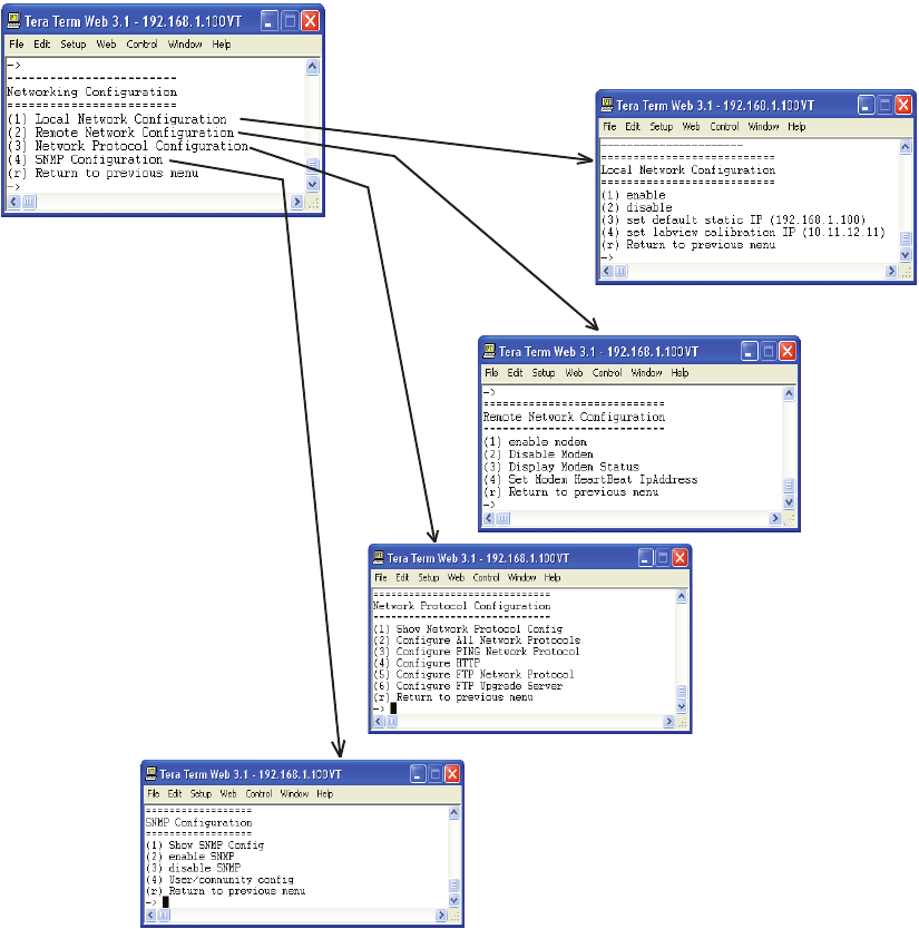
Networking Confi guration
If the user is unclear about the network confi guration that should be used for setup of the Co-Pilot Beacon, he or she should contact the
Network Administrator for information with regard to the specifi c network settings.
-32-
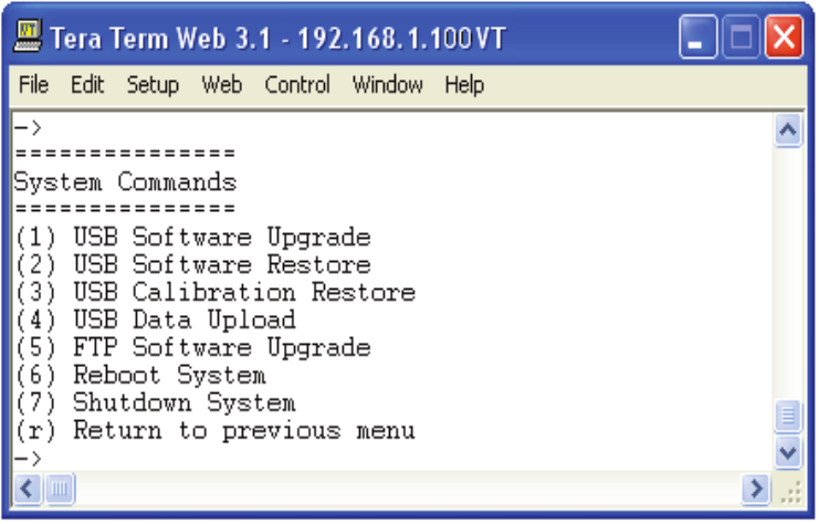
System Commands
The System Commands Menu will allow the user to upgrade and restore the unit OS, restore factory calibration settings, upload new data
fi les, upgrade FTP software, reboot and shutdown the system.
-33-
Key Features
Multiple Beacon Confi guration
Each unit contains four independent beacons. These can be all in the same band or two of one band and two of another.
Detected RF Power Shutdown
The product contains an RF power detector for each transmitter that can be used to sense the power being transmitted by the DAS.
Loss of the DAS requires that the beacon be shut down in order to provide some possibility for mobile devices to connect to the low level
signal of the macro network.
The shutdown threshold is set by the user. When the detected power falls below the set threshold the transmit power of all beacons is
shut down and an alarm is issued. When the power rises above the threshold the beacons are turned back on.
Timing Reference Source
A GPS derived timing reference is always required for the proper operation of the Co-co-pilot beacon. That timing reference can be
provided by one of the following:
• An optional internal GPS receiver
• An optional internal CDMA timing receiver
• The CSI supplied external CDMA Timing Reference Receiver
• The CSI supplied external precision GPS Timing Reference (Spectrum Instruments TM-4)
• Any user-supplied GPS Receiver capable of providing a TTL compatible even second tick aligned to GPS (not UTC)
time.
Control Parameter Details
Master Shutdown
The Master Shutdown shuts down the transmissions from all beacons in the product.
Timing Reference Selection
There are three alternatives for the timing reference source and all beacons in the product use the same reference.
• Internal GPS
• Internal CDMA
• External Even Second Sync
The choices that are available will depend on the product type as follows:
-MX- “External” only
-MG- “External” and “Internal GPS”
-MO- “External” and “Internal CDMA
The default choice will also depend on the product type as follows:
-MX- “External”
-MG- “Internal GPS”
-MO- “Internal CDMA
Selecting “Internal GPS” enables the use of the internal GPS receiver. An appropriate antenna with a clear view of the sky must be
connected to the “Timing In” connector of the Co-pilot beacon. This choice is only available if the unit includes the optional GPS timing
reference.
Selecting “Internal CDMA” enables the use of the internal CDMA receiver. Either an appropriate antenna, or a cable carrying a valid
CDMA Base Station signal, must be connected to the “Timing In” connector of the Co-pilot beacon. This choice is only available if the unit
includes the optional CDMA timing reference.
Selecting “External Even Second” enables the use of a TTL compatible even second pulse via the “EST In” connector of the Co-Co-pilot
beacon. The rising edge of the pulse is used as the time reference and must be aligned with the start of the even second of GPS (not
UTC) Time.
The even second tick provided by the selected Timing Reference will appear on the “EST Out” connector.
-34-
Each co-pilot beacon can transmit up to eleven simultaneous CDMA2000 signals. The carrier frequency for each signal is set by entering
the desired CDMA channel number for that signal.
Thus, there are eleven Channel Number fi elds, one for each of the possible signals.
The CDMA channel number is a unit less integer value
The range is 1 to 799 and then 991 to 1023 for cell band, 1 to 1199 for PCS band, and 25 to 875 for AWS band. Duplicate channel num-
bers are not allowed.
The default values for a Cell Band beacon are: The default values for a PCS Band beacon are:
Signal 1: CDMA Channel 1005 Signal 1: CDMA Channel 1
Signal 2: CDMA Channel 1 Signal 2: CDMA Channel 120
Signal 3: CDMA Channel 89 Signal 3: CDMA Channel 239
Signal 4: CDMA Channel 177 Signal 4: CDMA Channel 358
Signal 5: CDMA Channel 265 Signal 5: CDMA Channel 477
Signal 6: CDMA Channel 353 Signal 6: CDMA Channel 596
Signal 7: CDMA Channel 441 Signal 7: CDMA Channel 715
Signal 8: CDMA Channel 529 Signal 8: CDMA Channel 834
Signal 9: CDMA Channel 617 Signal 9: CDMA Channel 953
Signal 10: CDMA Channel 705 Signal 10: CDMA Channel 1072
Signal 11: CDMA Channel 793 Signal 11: CDMA Channel 1192
The default values for a AWS Band beacon are: Channel to frequency formulas are shown below:
Signal 1: CDMA Channel 25 Cell Channels 1-799 - .03 x (Ch# + 870) = (Frequency)MHz.
Signal 2: CDMA Channel 110
Signal 3: CDMA Channel 195 Cell Channels 991-1023 - .03 x (Ch# - 1023)+870 = (Frequency)MHz.
Signal 4: CDMA Channel 280
Signal 5: CDMA Channel 365 PCS Channels 1-1199 - .05 x (Ch# + 1930) = (Frequency)MHz.
Signal 6: CDMA Channel 450
Signal 7: CDMA Channel 535 AWS Channels 25-875 - .05 x (Ch# +2110) = (Frequency)MHz.
Signal 8: CDMA Channel 620
Signal 9: CDMA Channel 705
Signal 10: CDMA Channel 790
Signal 11: CDMA Channel 875
Each of the eleven signals for a given beacon can be individually turned on or off. There is one transmit enable fi eld for each signal.
The default values for Cell Band beacons are: The default values for PCS Band beacons are:
Signal 1: Enabled Signal 1: Disabled
Signal 2 Enabled Signal 2 Disabled
Signal 3: Enabled Signal 3: Disabled
Signal 4: Enabled Signal 4: Disabled
Signal 5: Enabled Signal 5: Disabled
Signal 6: Enabled Signal 6: Disabled
Signal 7: Enabled Signal 7: Disabled
Signal 8: Disabled Signal 8: Disabled
Signal 9: Disabled Signal 9: Disabled
Signal 10: Disabled Signal 10: Disabled
Signal 11: Disabled Signal 11: Disabled
The default values for AWS Band beacons are:
Signal 1: Disabled
Signal 2 Disabled
Signal 3: Disabled
Signal 4: Disabled
Signal 5: Disabled
Signal 6: Disabled
Signal 7: Disabled
Signal 8: Disabled
Signal 9: Disabled
Signal 10: Disabled
Signal 11: Disabled
Channel Frequency Numbers
Signal Transmit Enables
-35-
PN Offset
Each beacon has its own PN Offset. The PN Offset is a unitless integer value with a range of 0 to 511. The default value is zero.
Tau (Delay Correction)
There is a single Tau value for each beacon in a given product unit. Tau is a real value in units of microseconds with a range of -166.7 to
+166.7 μsec and one decimal place of precision. Internally the value will be rounded to the nearest 1/40th of a CDMA chip.
Co-pilot beacon Per Channel Transmit Power
This setting controls the CDMA Channel Power output by a given Co-pilot beacon for each carrier. All enabled carriers are transmitted at
the same power level. The total transmit power will be the sum of the power of all enable carriers. The user must set this power level such
that the total transmit power does not exceed the specifi ed maximum transmit power for the Co-pilot beacon.
The Output Power is specifi ed in dBm with a range of 0.0 to 20.0 and a resolution of 0.5.
Composite Transmit Power
Composite output power is a display only fi eld. The value is calculated from the Per Channel Tx Power and the number of channels that
are enabled.
Manual Shutdown
Manual Shutdown allows the user to shut down transmission from the given beacon
Auto Shutdown Enable
The detected power shutdown feature can be enabled or disabled.
Auto Shutdown Threshold
The shutdown threshold is entered in units of dBm.
The allowable range is -26 to +4 dBm
Detected Power
Detected power is a display only fi eld that displays the current reading of the power detector for the given beacon. The measured power
is displayed in units of dBm and has a range of -30 to +10.
-36-
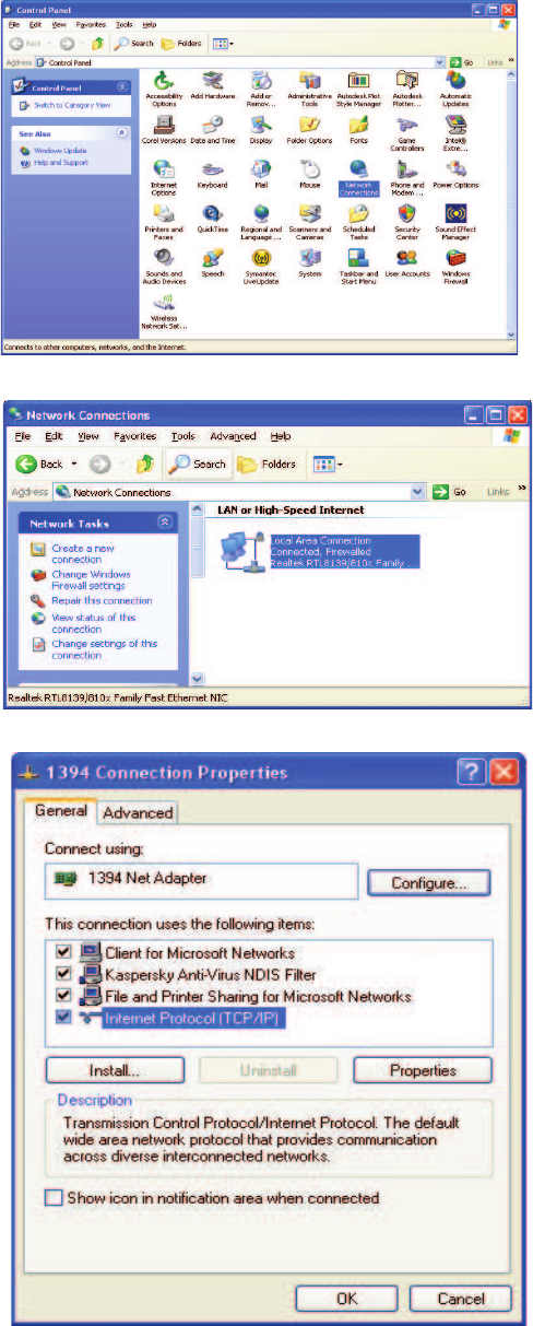
Instructions to change TCP/IP settings on your Windows computer.
Click in the Network Connections Icon in the Control Panel. See below.
Right click on Local Area Connection - and select “Properties”.
Scroll down to “Internet Protocol (TCP/IP) and click on the “Properties” button.
Additional Tips
-37-
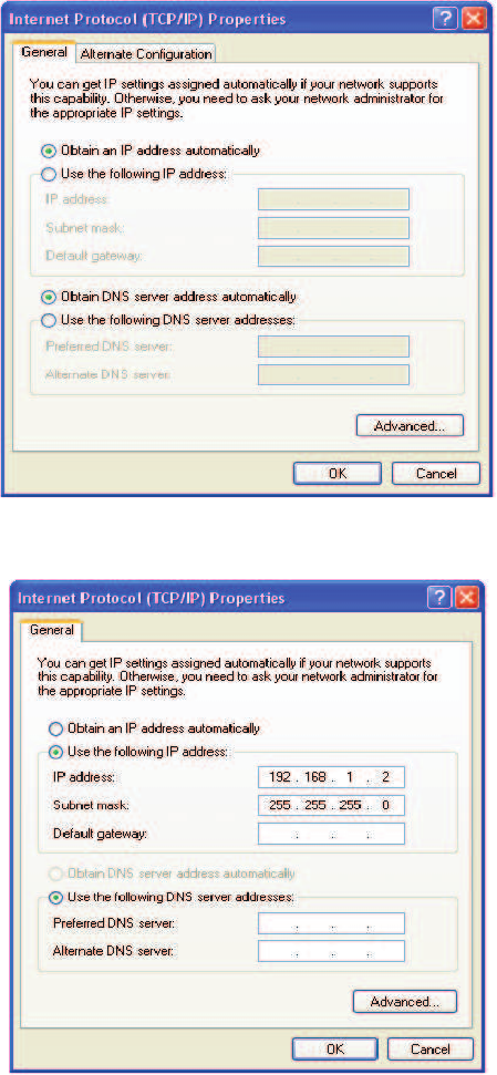
If you are set up to use DHCP, the window shown below will be displayed.
Select “Use the following IP address:” and enter “192.168.1.2.” The subnet mask should automatically populate to “255.255.255.0”.
Nothing else will need to be chosen or entered. Click “OK”, then “OK again and retry connection.
A crossover Ethernet cable (supplied) must be used for Web Interface access. As a reminder, you must verify the Ethernet port on your
laptop is powered. If your laptop is on battery power, the Ethernet port may be inactive by default. If this is the case simply plug in the
laptop to a 110vac source or change the power settings to enable the Ethernet port when the laptop is using battery power.
-38-

Seller warrants that its products are transferred rightfully and with good
title; that its products are free from any lawful security interest or other lien
or encumbrance unknown to Buyer; and that for a period of one year from
the date of installation or fi fteen months from the date of original shipment,
whichever period expires fi rst, such products will be free from defects in
material and workmanship which arise under proper and normal use and
service. Buyer’s exclusive remedy hereunder is limited to Seller’s correc-
tion (either at its plant or at such other place as may be agreed upon be-
tween Seller and Buyer) of such defects by repair or replacement at no cost
to Buyer. Transportation costs in connection with the return of products
to Seller’s plant or designated facility shall be paid by Buyer. The provi-
sions of this warranty shall be applicable with respect to any product which
Seller replaces pursuant to it. SELLER MAKES NO WARRANTY, EXPRESS
OR IMPLIED, OTHER THAN AS SPECIFICALLY STATED ABOVE. EXPRESS-
LY EXCLUDED ARE THE IMPLIED WARRANTIES OF MERCHANTABILITY
AND FITNESS FOR PURPOSE. THE FOREGOING SHALL CONSTITUTE ALL
OF SELLER’S LIABILITY (EXCEPT AS TO PATENT INFRINGEMENT) WITH
RESPECT TO THE PRODUCTS. IN NO EVENT SHALL SELLER BE LIABLE
FOR SPECIAL, CONSEQUENTIAL OR INCIDENTAL DAMAGES, INSTALLA-
TION COSTS, LOST REVENUE OR PROFITS, OR ANY OTHER COSTS OF
ANY NATURE AS A RESULT OF THE USE OF PRODUCTS MANUFACTURED
BY THE SELLER, WHETHER USED IN ACCORDANCE WITH INSTRUCTIONS
OR NOT. UNDER NO CIRCUMSTANCES SHALL SELLER’S LIABILITY TO
BUYER EXCEED THE ACTUAL SALES PRICE OF THE PRODUCTS PROVID-
ED HEREUNDER. No representative is authorized to assume for Seller any
other liability in connection with the products.
One Year Limited Warranty
Industry Certifi cations/Registration Numbers NVRCSI-CPBRW-CP, NVRCSI-CPBRW-AW
UL - Power Supply: UL60950-1
-39-
Index
A
AC Current 6
AC Power Frequency 6
AC Power Specifi cations 6
Acronyms and Defi nitions 5
AC Voltage 6
Additional Tips 37
Administration Tasks Collapse/Expand Icon 20
Administration Tasks Panel 15
Alarms Tab 17
Alarm Status Icon 19
Application 4
Auto Shutdown Enable 36
Auto Shutdown Threshold 36
B
Box Weight 6
C
Channel Frequency Numbers 35
Collapse/Expand Icon 19
Composite Transmit Power 36
Control Parameter Details 34
Co-Pilot Beacon Confi guration 30
Co-pilot beacon Per Channel Transmit Power 36
Copy Logs Icon 18
D
Depth 6
Detected Power 36
Detected RF Power Shutdown 34
E
EIA232 Pin Specifi cations 22
Element Management System 13
Elements Collapse/Expand Icon 21
Environmental Requirements 6
Explosive Atmospheres 4
F
Functional Overview: 6
G
Grounding 4
H
Height 6
I
Important Installation Notes 11
Industry Certifi cations/Registration Numbers 39
Install Software Icon 18
K
Key Features 34
L
Lightning Danger 4
Limited Warranty 39
Local Communication Interface Ports 11
Login 25
M
Main Menu 25
Manual Shutdown 36
Master Shutdown 34
Mechanical Drawing 7
Mechanical Specifi cations 6
Monitoring & Alarms 22
Multiple Beacon Confi guration 34
N
Networking Confi guration 32
null modem adapter 23
O
Optional Accessories 11
P
PN Offset 36
Powering Up the Unit 11
Power supply cable connectors 11
Product Introduction 5
Product Registration Information 4
R
Reboot Icon 18
Relative Humidity 6
S
serial cable 23
Set Parameters Menu 26, 29
Setup Element Confi guration Tab 17
Signal Transmit Enables 35
SNMP Confi guration Tab 16
Supplemental Confi guration Tab 16
Surface Coating 6
System Commands 33
System Confi guration 31
System Info Tab 13
System Set-Up Considerations 7
T
Tau (Delay Correction) 36
TCP/IP settings 37
Telnet Session 26
Telnet Session (Remote Access) 26
Temperature Range 6
terminal emulation programs 24
Text Menu Interface 23
Thermal Management 6
Timing Reference Selection 34
Timing Reference Source 34
Transmitter Confi guration 30
U
UL - Power Supply 39
USB Interface 22
User Interface 25
W
Warranty 39
Web based GUI Session 12, 23
Width 6
-40-

Notes

Notes

Notes

960-1146-002 rev 006