Westell CSIPS51080PS78 Public Safety Repeater User Manual
Westell, Inc. Public Safety Repeater Users Manual
UserManual.wiki
>
Westell
>
CSIPS51080PS78 User Manual
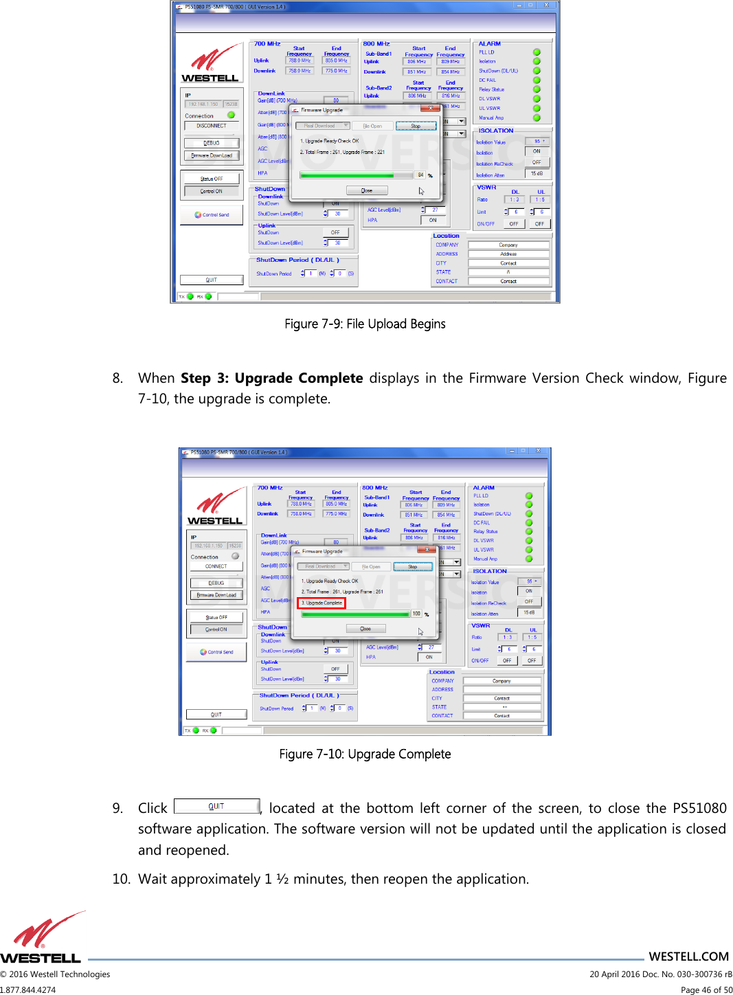
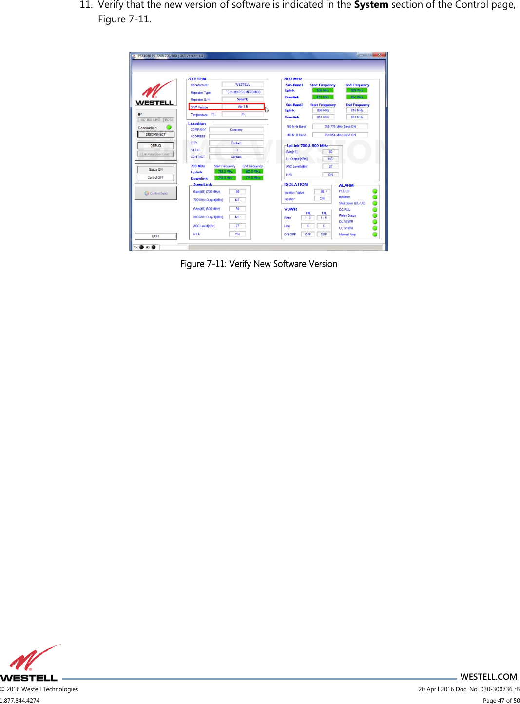
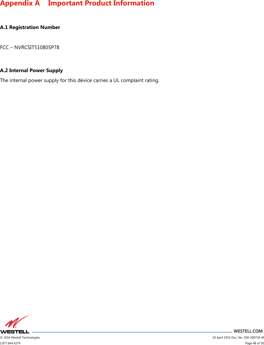
Users Manual
Navigation menu
Upload a User Manual
Namespaces
Wiki Guide
HTML
PDF
Info
Views
User Manual
Discussion / Help
Navigation