Westell CSIT61080-10W Bidirectional Amplifier User Manual D960 1043 001 rB MANUAL Tango dual 700 800 pmd
Westell, Inc. Bidirectional Amplifier D960 1043 001 rB MANUAL Tango dual 700 800 pmd
Westell >
Exhibit D Users Manual per 2 1033 c3
CSI Bi-Directional Amplifier
CSI Bi-directional Amplifier
CSI-T61080-10W-SP78 &
CSI-T61080-10W-WSP78
Installation Manual

Table Of Contents
Product Registration/Certification Information ................ 1
Safety Guidelines .......................................................... 1
Product Information ....................................................... 2
LED Indicators .............................................................. 2
Pin-Out Chart ................................................................ 2
Control and Connector Locations................................... 3
Mechanical Mechanical Outline Drawing ....................... 3
Installation..................................................................... 4-5
Important Safety Information .......................................... 5
Band Selection.............................................................. 6
Performance Adjustment ............................................... 6-17
View Menu Flow Diagram ................................. 7
View Menu Series ............................................ 7-11
Edit Menu Flow Diagram .................................. 12
Edit Menu Series ............................................. 12-17
Troubleshooting ............................................................. 18
Product Warranty .......................................................... 19
- 1 -
The serial number may be found on the label on the rear panel of the unit. For
your convenience, note this number below. Retain this manual, along with
proof of purchase, to serve as a permanent record of your purchase for future
reference or in the event of theft.
Product Certification/Registration Information
Safety Guidelines
The general safety information in this guideline applies to both operat-
ing and service personnel. Specific warnings and cautions will be found
in other parts of this manual where they apply, but may not appear in
this summary. Failure to comply with these precautions or specific
warnings elsewhere in the manual violates safety standards of design,
manufacture, and intended use of equipment. Cellular Specialties, Inc. assumes no
liability for the customer’s failure to comply with these requirements.
Grounding
This amplifier system is designed to operate from 120 Vac @ 1.3A maxpower
and should always be operated with the ground wire properly connected. Do
not remove or otherwise alter the grounding lug on the power cord.
Explosive Atmospheres
This product has an integral circuit breaker, which may cause an electrical flash
if the breaker should reset. To avoid explosion or fire, do not operate this product
in the presence of flammable gases or fumes.
Lightning Danger
Do not install or make adjustments to this unit during an electrical storm.
HAZARDOUS VOLTAGES MAY BE PRESENT WHEN THE COVER IS OPEN.
tampering with the chassis will void your warranty. If you suspect a malfunction
with this product, call your dealer or the Cellular Specialties Support Line at
(603) 626-6677.
DISCLAIMER: All information and statements contained herein are accurate to the best of the knowledge of
Cellular Specialties, Inc. (CSI), but Cellular Specialties makes no warranty with respect there to, including without
limitation any results which may be obtained from the products described herein or the infringement by such
products of any proprietary rights of any persons. Use or application of such information or statements is at the
users sole risk, without any liability on the part of Cellular Specialties, Inc. Nothing herein shall be construed as
license or of recommendation for use, which infringes upon any proprietary rights of any person. Product
material and specifications are subject to change without notice. Specialties’ standard terms of sale and the
specific terms of any particular sale.
MODEL NUMBER SERIAL NUMBER DATE OF PURCHASE
POINT OF SALE COMPANY

- 2 -
Product Description
Cellular Specialties, Inc. (CSI) developed this Bi-Directional Amplifier (BDA) for use
where sufficient signal from local repeater sites to operate public safety
communications devises was unavailable within the building. It is necessary that
sufficient signal be available on the roof of the structure. The BDA is connected to an
external antenna, usually on the roof, and to one or more internal antennas placed
strategically throughout the area where communications service is desired.
The external antenna is usually a directional type such as a “yagi”. Internal antennas
are usually omnidirectional, although various other types may be used for certain
installations. The BDA amplifies both the “uplink” (tranceiver to tower) and “downlink”
(tower to transceiver) signals thus facilitating communications to and from the local
repeater site. There are seven amplification stages on the downlink and seven on
the uplink for a total of +80 dB nominal gain for each link. Gain can be set using the
LCD display and select/up/down switches. There are also LED indicators for power
overload and gain reduction to prevent oscillation.
LED Indicators (located on the User Interface Control Panel)
Warning: The unit has sensed instability due to insufficient isolation
between the inside antenna and the outside antenna, and has
reduced the gain of the amplifier. This is done to prevent oscilla-
tion, which can interfere with the handsets in the covered area
and/or the base station.
Fault:(Red) The gain of the unit has been reduced to a minimum in order
to prevent very strong input signals from overloading the
amplifier. The amplifier will attempt to recover from this condi-
tion, initially at fifteen second intervals and then at four-minute
intervals.
Pin-Out Chart
Pin Description
1 5 Volts
2 Center Contact Alarm Relay
3 Alarm Contact-Open
4 Alarm Contact-Closed
5 Shut Down
6 Ground
An automatic amplifier safety shutdown circuit is
also incorporated that will disable the transmit-
ter, to prevent excessive intermodulation and
oscillation, should the uplink or downlink over-
loads be reached . The amplifier will periodically
attempt to recover from this condition.
The BDA is equipped with an internal interface
connector (RJ-15) designed for use with an
optional remote monitor. A second Connector (RJ-
11) mounted externally is used for remote
monitoring and shutdown. The RJ-11 pin-out is
listed here.
•Pins 3 & 4 will toggle from open to closed
with faults.
•Pin 1 (5 Volts) can be tied to Pin 5 to
shut the unit down.
- 3 -
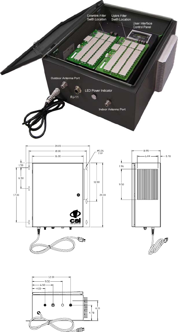
Mechanical Drawing
STA TU S
POR T INSIDE
ANTE NN A
POWEROUTSIDE
ANTE NN A
Control and Connector
Locations
- 4 -
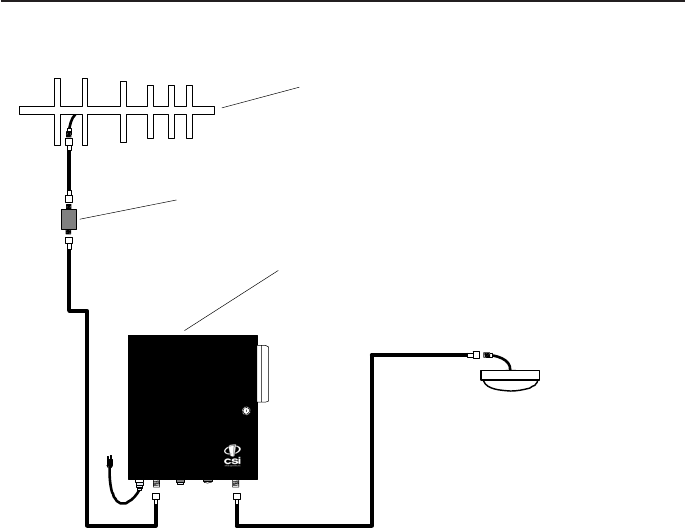
Installation
Indoor Server Antenna
Outdoor Donor Antenna Antenna located on roof of building and
grounded in accordance with NEC 810-15, 21.
Align antenna with donor site to achieve
highest signal strength reading
Lightning arrester located at building
penetration point and grounded.
CSI-T61080-10W-SP78 or CSI-T61080-10W-WSP78
Bi-Directional Amplifier
Example: Typical Single Internal Antenna System Design
Optional Accessories
A complete line of accessories is available from Cellular Specialties, Inc. Check with your CSI
distributor for any additional items needed. Below are just a few examples suitable for most in-
building needs.
•Outside Donor Antenna
SMR700&800 - model number: CSI-AY/700-960/11
•Inside Omnidirectional Antenna
Quad-band - model number (CSI-AO/700/2.5K/3)
•Power Dividers
2:1 - model number (CSI-SPD2/700-2.5K/N)
3:1 - model number (CSI-SPD3/700-2.5K/N)
4:1 - model number (CSI-SPD4/700-2.5K/N)
•Grounding Kit - model number (CSI-GKIT)
•Lightning Arrestor - model number (CSI-CAP)
•Directional Couplers and Cross Band Couplers are also available.
6dB - model number (CSI-DC6/700-2K/N)
10dB - model number (CSI-DC10/700-2K/N)
15dB - model number (CSI-DC15/700-2K/N)
20dB - model number (CSI-DC20/700-2K/N)
30dB - model number (CSI-DC30/700-2K/N)

- 5 -
•A high degree of isolation must be afforded to prevent any re-generative
feedBack in the system. FeedBack of this nature causes the amplifier to emit a
continuous signal of maximum amplitude and could, in some cases, interfere with
normal operation of the donor site. The use of window mounts or other non-rooftop
mountings antennas should be avoided.
•The Installer should refer to the Safety Precautions, in the following section, for
proper antenna selection and installation
Important Installation Notes
WARNING! AMPLIFIER OR HANDSET DAMAGE MAY OCCUR IF A
HANDSET IS CONNECTED DIRECTLY TO THE BDA OR THE COAX THAT
LEADS TO THE BDA.
Important Safety Information
!For INDOOR
use, an
omnidirectional
antenna with a
maximum gain of 3
dBi is authorized for use with this
unit. Inside antennas must be
positioned to observe minimum
separation of 120 cm. (~ 4 ft.) from
all users and bystanders. For the
protection of personnel working in
the vicinity of inside (downlink)
antennas, the following guidelines
for minimum distances between the
human body and the antenna must
be observed.
The installation of an INDOOR
antenna must be such that, under
normal conditions, all personnel
cannot come within 120 cm. (~ 4.0
ft.) from any inside antenna.
Exceeding this minimum separation
will ensure that the employee or
bystander does not receive RF-
exposure beyond the maximum
permissible exposure according to
section 1.1310 i.e. limits for
General Population/Uncontrolled
Exposure.
For OUTDOOR use, a directional
antenna up to a maximum gain of
11dBd is authorized for use with this
unit.The outside antenna must be
positioned to observe minimum
separation of 120 cm. (~ 4 ft.) from
all users and bystanders. For the
protection of personnel working in
the vicinity of outside (uplink)
antennas, the following guidelines
for minimum distances between the
human body and the antenna must
be observed.
The installation of an OUTDOOR
antenna must be such that, under
normal conditions, all personnel
cannot come within 120 cm. (~ 4
ft.) from the outside antenna. In all
installations, the antenna should
never be mounted such that the
main beam is directed toward an
area where workers or bystanders
may be present. Exceeding this
minimum separation will ensure
that the worker or bystander does
not receive RF-exposure beyond
the Maximum Permissible
Exposure according to section
1.1310 i.e. limits for General
Population/Uncontrolled Exposure.
- 6 -
Performance Adjustment
The menu system can be navigated with five buttons: UP, DOWN, EDIT,
SAVE, and MENU. Feedback is given to the operator through the LCD panel.
The LCD Command Interface offers two distinct series of menus: the View
Menu Series, which allow a user to view, but not alter, certain bits of data the
unit maintains; and the Edit Menu Series, which permit the alteration of this
information. The Edit Menu Series are kept secure from general use by a
password, if password control is invoked, so that curious or malicious people
cannot randomly alter data. However, this unit is shipped with this feature
disabled. See page 16 for further details.
In both menu systems the MENU button is used to maneuver between menus
in a sequential fashion. EDIT is generally used to enter the Edit Menu Series,
and SAVE is generally used to exit it. (Pressing SAVE in all menus except
the one that allows you to alter the Edit BDA Name menu (explained below)
will force any changes made while in the Edit Menu Series to be saved in non-
volatile memory. The BDA will then exit the Edit Menu Series; if the user
needs to edit more information, they will need to press EDIT and enter a
password again.) The UP and DOWN buttons are usually used to scroll
through options within a given menu, if several options exist.
What follows is an exploration of each menu series in detail, and how each
menu represents and interprets data.
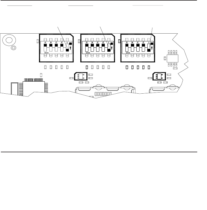
C & KDN DN C & K C & KDN
800 Band 2
UL: 817MHz-824MHz
DL: 862MHz-869MHz
(Control switch shown in
the default ON condition.)
800 Band 1
UL: 806MHz-815MHz
DL: 851MHz-860MHz
(Control switch shown in
the default ON condition.)
700MHz Band
UL: 793MHz-805MHz
DL: 763MHz-775MHz
(Control switch shown in
the default ON condition.)
Band Selection for Channelized Units Only
Note: each channelized BDA is shipped with all bands active (all number 1
switch locations set to the ON position for both up and down links.) To prevent
a band from being passed by the BDA, set the desired band switch off. This
will filter out that band. Note: switch positions 2-5 on each of the band
controls are inactive and not used. It is also important to set the switches on
the uplink and downlink controls in the same positions.
- 7 -
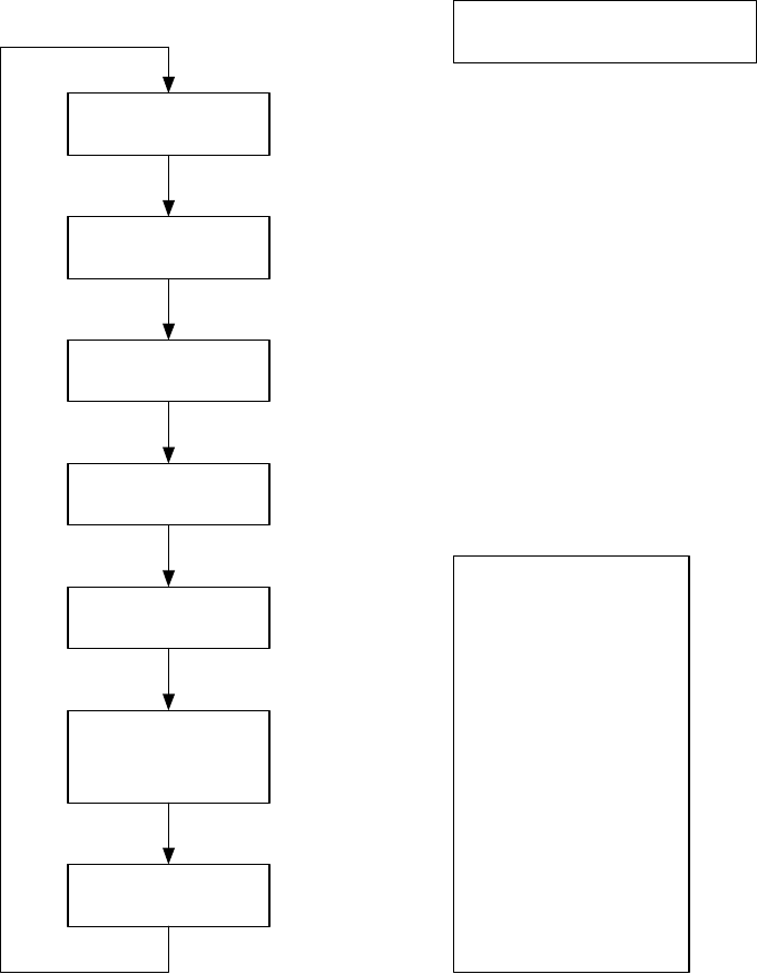
The View Menu Series
View Menu Tree
Screen Saver
Power Readings
Oscillation Events
Overheat Events
Peak Power
Readout
Uplink and
Downlink
Maximum Gain
BDA Name and
Address
MENU
MENU
MENU
MENU
MENU
MENU
MENU
any key Page 8
Page 8
Page 9
Page 9
Page 10
Page 10
Page 11
This series of menus will allow
the user to view, but not alter,
the information stored in the
BDA. Pressing the EDIT button
will cause the BDA to ask for a
password, if password control is
invoked. Password control is
invoked by pressing EDIT and
MENU simultaneously. The
password is a five button
sequence that secures the ability
to change the information within
the BDA. Keys in this password
can consist of any button except
MENU.
This password defaults to the
following sequence until changed
by the user:
UP, DOWN, DOWN, UP, UP
- 8 -
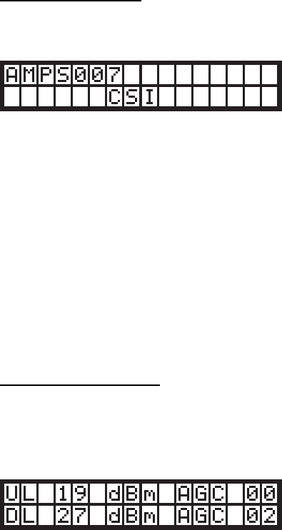
Screen Saver Display
Upon powering up the BDA, a display resembling this will appear on the LCD
panel:
The first row contains the network name of the BDA; this allows the user to
determine which BDA they are looking at. This name can be changed to
whatever the user desires, and can contain blank spaces, capital letters,
lowercase letters, and numerals. It is limited to seven characters to facilitate
communication with a Web Monitor, should one be desired.
This screen is known as the Screen Saver Display because it is the screen
that the BDA will revert to showing if there has been no activity detected on
the keypad for at least ten minutes. If this occurs, the LCD backlight will shut
off to save power and prevent the backlight from burning out. Pressing any
key other than EDIT while in the Screen Saver Display will turn the backlight
back on, and advance the menu to the Power Readout Display. Pressing the
EDIT key will advance you to the EDIT menu series.
Power Readings Display
This menu shows the instantaneous power readings in the BDA, as well as
whether or not the gain is being actively attenuated by Automatic Gain
Control.
A typical Power Readings Display might appear as below:
This shows that the composite power is currently 19 dBm on the output of the
uplink pass band; 27 dBm on the output of the downlink pass band; and
Automatic Gain Control has attenuated the signal 2 dB on the downlink pass
band.
It should be noted that when the power through a channel is less than 0 dBm,
the display will show “<0” in the location where the reading usually appears.
This prevents spurious power readings from occurring because of random
noise.
The UP, DOWN, and SAVE buttons have no effect in this menu. Pressing the
MENU button, however, will advance the user to the Event Readout displays.

- 9 -
Event Readout Displays
Three performance measures are tracked within the BDA, and are recorded
and displayed as events. Up to 999 of each type of event is recorded. If more
than this number of events are detected, the menu system will continue to
display the maximum number of 999.
A typical display might look like this:
Three types of service affecting events that the BDA records can be viewed
within separate windows. Pressing the MENU button will sequence through
these displays. The first window in the sequence displays isolation control
events, and the next abnormal temperature events. A fourth menu press will
display a recording of the UL and DL peak power.
After a window has been bypassed, all windows selectable thru menu presses
must be viewed in order to return to the last viewed display.
Any event will cause a yellow (WARNING) LED to illuminate. The warning
LED can be extinguished by resetting the appropriate event counter(s) via the
EDIT menu or by cycling the primary power. Cycling primary power will reset
the counters as well. Events capable of being recorded are:
•Isolation Control: This event is recorded whenever insufficient
isolation exists between the outdoor and indoor antenna. When that
condition occurs, the Oscillation Event counter will be incremented.
Oscillation control is implemented in the BDA control system. If an
oscillation condition is detected, the BDA control circuitry will attempt
to stabilize the system by immediately reducing the gain 3 dB. A
warning will also be immediately displayed that shows the
accumulated change on the affected link(s) e.g. [UL (003 dB attn).
After a period of time, the system will recheck itself and continue to
reduce the gain in 3 dB increments until the oscillation conditions no
longer exists. Each gain reduction is counted as an event. At some
point, if stability cannot be reached, the BDA amplifier on the affected
link will be shut down. After shutdown, or at any point after stability is
reached, the system will attempt to fully recover lost gain. Until the
system can recover to the original gain setting, the warning LED will
remain illuminated.

- 10 -
•Over Temperature Limit: Amplifier junction temperature is monitored
continuously. If the temperature rises above a factory determined
limit, an Overheat Event will be recorded. If the event is transitory,
each excursion above the limit will increment the Overheat counter. A
yellow LED will remain illuminated until the counter is reset to zero.
Event counters serve as diagnostic tools for maintenance and system health
assessments. Only isolation control will alter the intended performance of the
system. Overheat events have no effect on the BDA.
Pressing MENU within this display will advance the user to the Peak Power
Display.
Peak Power Readout Display
This display shows the highest readings that have registered on the BDA
since power-up or reset.
A typical display might look like this:
Note that since AGC cannot act instantaneously, the peak power seen on the
output might be higher than the power the unit is capable of sustaining. This
is not an error, but an indication that the power did exist – briefly – at the
output port. This is meant to aid in diagnostics if necessary.
Pressing the MENU button will advance the user to the Downlink Gain display.
Gain Display
This display indicates the gain applied to the uplink or downlink pass band.
These values might differ if an offset has been applied.
A typical gain display might look like this:
Pressing the MENU button will advance the user to the BDA Name Display.
- 11 -
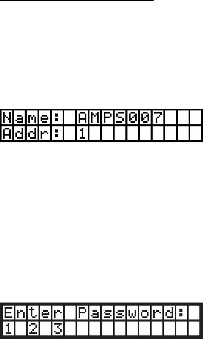
BDA Name and Address Display
In addition to its name, a BDA can be uniquely identified on a network with a
Web Monitor by its name. The name here is identical to the one in the
Screen Saver Display. The BDA name is limited to seven characters. Each
BDA accesible by a single Web Monitor on the network must have a unique
address within that network between one and seven, inclusive. This display
also shows the current BDA’s network address.
A typical BDA name and address display might look like this:
Pressing the MENU button will return the user to the Screen Saver display.
Note that pressing the EDIT button in any of these displays will cause the
BDA to enter the EDIT menu series. A password will be requested from the
user if password control has been invoked. Successful password entries will
permit the user to enter the Edit Menu Series; unsuccessful entries will cause
the BDA to revert to the Screen Saver display. The password menu does not
belong to either the View Menu Series or the Edit Menu Series. It is shown
here for completeness.
A typical password entry display might look like this:
Each password consists of a series of five button presses. None of the
buttons can be MENU. Pressing the menu button or entering an invalid key
in the password key sequence will cause an immediate exit to the Screen
Saver display. In order to keep the password masked as it is entered, the
bottom row reveals how many keys have been entered in the password thus
far. In the example shown, then, three out of the five-key presses have been
received and validated. Regardless of which display the user was viewing prior
to entering the password mode, successful password entry will take them to
the Edit Oscillation Events display.
- 12 -
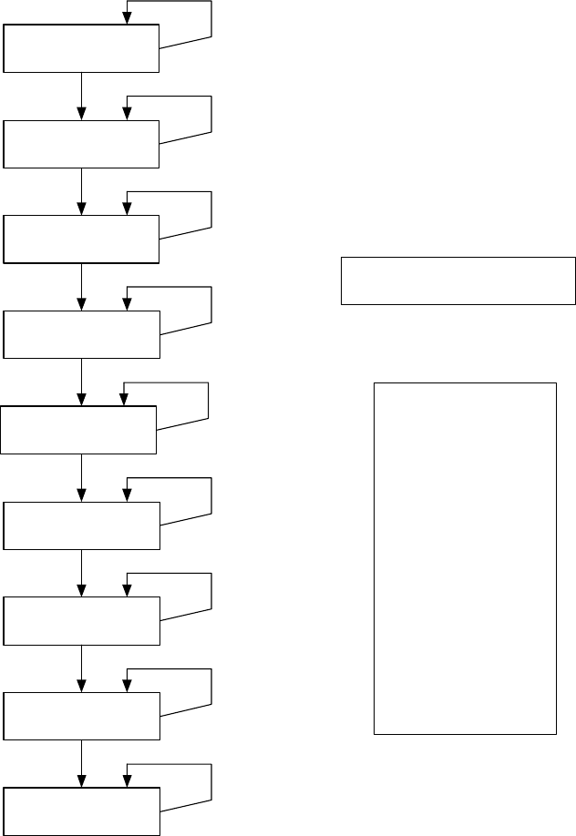
The Edit Menu Series
Edit Menu Tree
Software
Shutdown
Downlink Gain
Oscillation Events
Overheat Events
Peak Power
Readout
BDA Name
MENU
MENU
MENU
MENU
MENU
MENU
MENU
EDIT
Page 13
This series of menus will allow
the user to alter the information
stored in the BDA. These menus
are only accessible if the user
has a password, if password
control is invoked. After getting
into this sequence of menus, the
user can save all changes made
by pressing SAVE. Pressing this
button exits the edit menu series.
However, it is advisable to made
all desired changes before
pressing the SAVE button.
(The Edit BDA Name menu is an
exception; refer to the
documentation for details.) If no
button is pressed within ten
minutes of the last press, these
menus will be exited and no
changes made will be saved.
This password to enter the Edit
Menu Series defaults to the
following sequence until changed
by the user:
UP, DOWN, DOWN, UP, UP
Uplink Gain
BDA Address
Create New
Password
MENU
MENU
EDIT
EDIT
UP
DOWN
UP
DOWN
UP
DOWN
UP
DOWN
UP
DOWN
UP
DOWN
Page 13
Page 13
Page 14
Page 14
Page 14 & 15
Page 15
Page 15 & 16
Page 16

- 13 -
Edit Events Display
These displays will show you the number of events recorded two categories
(Oscillation and Overheat). Each MENU button press will move to the next
display. At any event category, pressing EDIT will clear the counter and rest
the number of events to zero.
To indicate that you are currently in the EDIT series, the first word in the top
line of the display will always be EDIT followed by the name of the display.
A typical EDIT EVENTS display might resemble the following:
.
Edit Peak Power Readout Display
This display will show the same information indicated in the View Menu
Series, however, pressing EDIT clears the peak power readings and captures
the current values.
A typical display might look like this:
Pressing MENU at this point will cause the BDA to enter the Edit Downlink
Gain display.
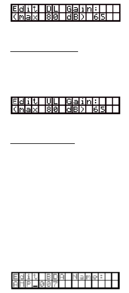
Edit Downlink Gain Display
In this window the downlink gain can be altered, however it cannot be adjusted
lower than the difference between the calibrated maximum output minus 30
dB (max gain -30 dB). The range of the attenuators in either the uplink or the
downlink imposes this constraint. Within that permissible range, the values
can be changed in 1 dB increments by pressing the UP or DOWN keys. If an
attempt is made to change the gain value beyond a 30 dB range, the value will
increment to the highest or lowest acceptable value depending on which end
of the constraint the attempt is initiated.
By example, for an 80 dB gain amplifier the minimum gain setting is 50 dB.
Pressing the DOWN key when 50 dB of gain is currently being displayed will
return gain setting to 80 dB. Likewise, if the gain setting is at 80 dB, pressing
the UP key will change the gain to 50 dB.
Using another illustration, an amplifier having a maximum gain of 65 dB will
have a minimum gain setting of 35 dB.
- 14 -
A typical downlink EDIT Display may look like this:
The MENU button will take the user to the Edit Uplink Gain display.
Edit Uplink Gain Display
This display is functionally identical to the Edit Downlink Gain display, but
alters the gain through the uplink pass band instead of the downlink pass
band.
A typical uplink EDIT Display may look like this:
Pressing the MENU key here will take the user to the Edit BDA Name display.
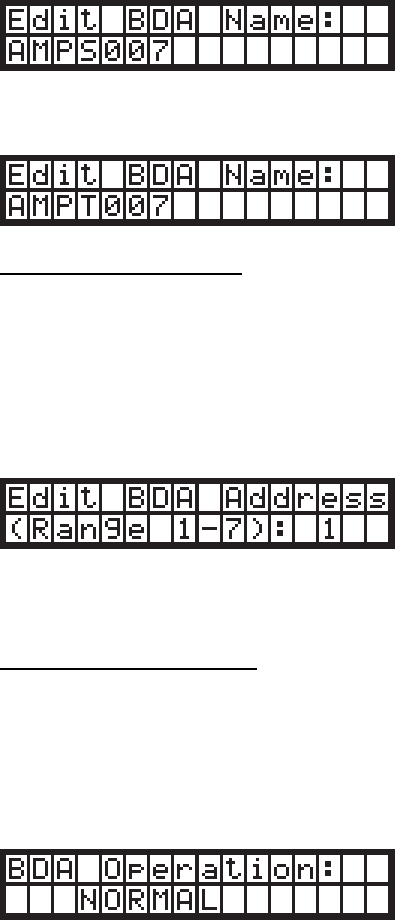
Edit BDA Name Display
This display will let the user set a new name for the BDA for identification
purposes on a Web Monitor network. This also changes the name shown on
the Screen Saver display and the BDA Name display. A name can consist of
uppercase letters, lowercase letters, numerals, and/or blank spaces.
A blinking cursor shows the user which letter they are editing; the edit
process is executed from left to right. In any cursor position, characters are
selected by using the UP and DOWN buttons. Once the user has selected
the letter for that position, SAVE will lock that letter into that position and
advance the cursor to the right. Pressing EDIT will back the cursor up one
space and permit the user to edit that letter again using the same process.
One cannot back up beyond the first character. Pressing SAVE on the
seventh character will cause the BDA to advance to the Edit BDA Address
display, as will pressing MENU at any time. Pressing MENU, however, will
cancel any changes that the user has made to the BDA name.
A typical display for this menu might look like this:
- 15 -
Example: In the above display the cursor shows that the user is at the fourth
character position. In the below display the user has used the UP and DOWN
buttons to select “S”. The cursor at that position will blink intermittently,
alternating with the character currently stored at that position:
Continuing the example, pressing UP at this point will illustrate the
advancement of the character at the current position to “T”:
Edit BDA Address Display
This screen permits the setting of a new address for a BDA on a Web Monitor
network. Valid values are from one to seven, inclusive. Care must be taken in
this menu not to set the address to that of another BDA on the same Web
Monitor network.
The different addresses permissible are presented in cyclical fashion.
A typical display might look like this:
Pressing UP and DOWN will scroll through the different valid addresses.
Pressing MENU will exit to the next screen: the Software Shutdown display.
Software Shutdown display
A software shutdown will prevent the BDA from functioning and will cease data
acquisition by the BDA processor. There are only two modes available, and
they can be selected by pressing UP and DOWN: NORMAL, which is the
regular form of BDA operation, and SHUTDOWN, which performs a software
shutdown of the BDA.
A typical display might look like this:
Once the BDA is shut down through software, the FAULT (red) LED will glow.

- 16 -
When the BDA operation mode is returned to NORMAL, the FAULT LED will
extinguish.
Pressing the MENU button at this point will cause the BDA to display the
Create New Password display.
Create New Password Display
This display will allow the user to enter a new password. The display,
however, will not be viewable until password control is invoked by first pressing
the proper keys simultaneously (SAVE and MENU). This operation will either
enable the default password (UP, DOWN, DOWN, UP, UP) if no password
change has ever been implemented, or the current password. Either
password sequence will be required to authorize a new password. Pressing
EDIT and MENU again will toggle the password off. This process will require
the current password to complete the action.
Pressing any button after a new sequence has been entered will cause that
sequence to be stored. Pressing MENU at any time during the sequence will
abort the process and revert to the most recent password. If a change is
successful, the new password will be required for future changes to be
enabled.
Password control cannot be disabled without authorizing the mode change
using the current password.
The change password process is much the same as the PASSWORD ENTRY
process described earlier.
The display that asks for the current password looks like this:
Once this has been entered, the request for the new password looks like this:
A password can only consist of the buttons UP, DOWN, and SAVE, since
EDIT and MENU have global functionality.
Pressing MENU will abort this and return to the Edit Events display.
None of the changes invoked take effect unless the user presses SAVE.
Once this input occurs, all changes are saved to non-volatile memory and the

- 17 -
BDA returns to the Screen Saver display. If the BDA does not detect any key
presses within ten minutes of the last key press, the BDA will discard all
changes made in the Edit Menu series since the last password entry and
revert to the Screen Saver display.
Final Note: If the BDA should become unstable, and none of these menu
commands are operable, the processor can be reset to factory defaults by
pressing and holding the UP, DOWN, and MENU buttons simultaneously for
one second. This is a catastrophic recovery measure and should not be
implemented unless all other procedures have failed.

- 18 -
Troubleshooting
All cables should be carefully checked for “shorts” and “opens”.
The rooftop antenna, if directional, should be checked for proper alignment along the
calculated compass heading. Typically, the directional antenna should be aimed at
the same site that your handset uses in the area where the outside antenna is
placed.
If cables and alignment are acceptable, it may be necessary to use a spectrum
analyzer to examine the signal environment in which the BDA is operating. The
existence of strong analog signals within the frequency bands can cause the AGC
to reduce the amplifier’s gain particularly on the downlink. In some cases additional
filtering might be required to reject these unwanted signals. In some instances the
directional outside antenna can be reoriented, horizontally to place the interfering
source in an antenna pattern “null”. There also may be some cases where the
interference from outside signals is so great that they can not be filtered or otherwise
reduced or eliminated without expensive and possibly prohibitive measures. In these
cases it may not be practical to use the BDA for providing coverage at these sites.
If a problem continues after the above steps are taken verify the dip switch
positions. Note: each channelized BDA is shipped with all bands active (all
number 1 switch locations set to the ON position for both up and down links.)
To prevent a band from being passed by the BDA, set the desired band switch
off. This will filter out that band. Note: switch positions 2-5 on each of the band
controls are inactive and not used. It is also important to set the switches on
the uplink and downlink controls in the same positions.

- 19 -
One Year Limited Warranty
Seller warrants that its products are transferred rightfully and with good title;
that its products are free from any lawful security interest or other lien or
encumbrance unknown to Buyer; and that for a period of one year from the
date of installation or fifteen months from the date of original shipment, which-
ever period expires first, such products will be free from defects in material and
workmanship which arise under proper and normal use and service. Buyer’s
exclusive remedy hereunder is limited to Seller’s correction (either at its plant
or at such other place as may be agreed upon between Seller and Buyer) of
such defects by repair or replacement at no cost to Buyer. Transportation costs
in connection with the return of products to Seller’s plant or designated facility
shall be paid by Buyer. The provisions of this warranty shall be applicable with
respect to any product which Seller repairs or replaces pursuant to it. SELLER
MAKES NO WARRANTY, EXPRESS OR IMPLIED, OTHER THAN AS SPECIFI-
CALLY STATED ABOVE. EXPRESSLY EXCLUDED ARE THE IMPLIED
WARRANTIES OF MERCHANTABILITY AND FITNESS FOR PURPOSE. THE
FOREGOING SHALL CONSTITUTE ALL OF SELLER’S LIABILITY (EXCEPT
AS TO PATENT INFRINGEMENT) WITH RESPECT TO THE PRODUCTS. IN
NO EVENT SHALL SELLER BE LIABLE FOR SPECIAL, CONSEQUENTIAL
OR INCIDENTAL DAMAGES, INSTALLATION COSTS, LOST REVENUE OR
PROFITS, OR ANY OTHER COSTS OF ANY NATURE AS A RESULT OF THE
USE OF PRODUCTS MANUFACTURED BY THE SELLER, WHETHER USED
IN ACCORDANCE WITH INSTRUCTIONS OR NOT. UNDER NO CIRCUM-
STANCES SHALL SELLER’S LIABILITY TO BUYER EXCEED THE ACTUAL
SALES PRICE OF THE PRODUCTS PROVIDED HEREUNDER. No represen-
tative is authorized to assume for Seller any other liability in connection with
the products.
Industry Certifications/Registration Numbers: FCC: NVRCSI-61080-10W

D960-1032-001 rev D ECO 1875
960-1043-001 rev B ECO2121