Westell CSIT61080-SP78 Bidirectional Amplifier User Manual 960 1048 001 r002 ChiPs FULL SIZE pmd
Westell, Inc. Bidirectional Amplifier 960 1048 001 r002 ChiPs FULL SIZE pmd
Westell >
Exhibit D Users Manual per 2 1033 c3
CSI-T51080-SP78
Installation Manual

Table Of Contents
Product Registration Information................................. 1
Document Purpose/Intended Users............................. 1
Application............................................................... 1
Safety Guidelines......................................................1
Product Introduction....................................................... 2
Product Features.......................................... 2
Special Installation Directions.........................2
System Block Diagram.............................................. 3
Product Specification................................................. 4
RF Specifications.......................................... 4
Power Specifications..................................... 5
Mechanical Specifications.............................. 5
Environmental Specifications.......................... 5
Alarm Interface..............................................6
Alarm Relay..................................................6
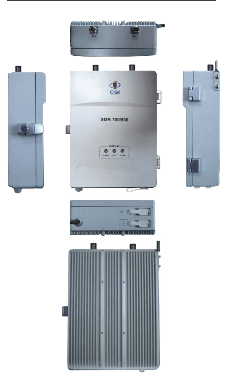
Product Appearance.................................................. 7
External Arrangement.................................... 7
Outline Drawing.............................................8
Internal Arrangement......................................9
PSU............................................................ 10
GUI(Graphic User Interface)........................................11
Program Introduction..................................... 11
GUI Setup.................................................... 11
Open Serial Communication Port.................... 15
Condition Check and Control.......................... 16
System Status Mode.....................................17
Normal Mode................................................ 17
Alarm Status Mode........................................18
Power Status Mode....................................... 18
Isolation Status Mode.................................... 19
Downlink...................................................... 20
Uplink.......................................................... 21
Frequency Information................................... 22
Band Select..................................................22
Shutdown Period........................................... 23
Control Send.................................................23
Management Mode........................................24
ADC.............................................................25
Compensation...............................................25
Normal......................................................... 25
Isolation Re-check.........................................26
Attenuation...................................................26
Power & Temp & Atten Table.......................... 27
OFFSET....................................................... 27
Debugging.................................................... 28
Downloading................................................. 29
Factory Settings........................................... 29
Product Warranty...................................................... 31
FCC Information........................................................ 31

- 1 -
Application
This guide should be applied whenever a need exists to add Digital Repeater capability to an
existing system or when this capability is being included with a new installation.
Safety Guidelines
The general safety information in this guideline applies to both operating and service personnel.
Specific warnings and cautions will be found in other parts of this manual where they apply, but
may not appear in this summary. Failure to comply with these precautions or specific warnings
elsewhere in the manual violates safety standards of design, manufacture, and intended use of
equipment. Cellular Specialties, Inc. assumes no liability for the customer’s failure to comply with
these requirements:
Grounding
This Digital Repeater system is designed to operate from 100-240 VAC @ 1.7A max. current
and should always be operated with the ground wire properly connected. Do not remove
or otherwise alter the grounding lug on the power cord.
Explosive Atmospheres
To avoid explosion or fire, do not operate this product in the presence of flammable
gases or fumes.
Lightning Danger
Do not install or make adjustments to this unit during an electrical storm. Use of a suitable
lightning arrester, such as CSI’s model number CSI-CAP, is very strongly recommended.
No User Serviceable Parts Inside
HAZARDOUS VOLTAGES ARE PRESENT WHEN THE COVER IS REMOVED. Opening the
chassis will void your warranty. If you suspect a malfunction with this product, call your dealer or
the Cellular Specialties Support Line at: (603) 626-6677.
The serial number may be found on the label on the panel near the power connec-
tors. Note this number below. Retain this manual, along with proof of purchase, to
serve as a permanent record of your purchase.
MODEL NUMBER SERIAL NUMBER DATE OF PURCHASE
POINT OF SALE COMPANY
Product Registration Information
DISCLAIMER: All information and statements contained herein are accurate to the best of the knowledge of Cellular Specialties,
Inc. (CSI), but Cellular Specialties makes no warranty with respect there to, including without limitation any results that may be
obtained from the products described herein or the infringement by such products of any proprietary rights of any persons. Use or
application of such information or statements is at the users sole risk, without any liability on the part of Cellular Specialties, Inc.
Nothing herein shall be construed as licence or recommendation for use, which infringes upon any proprietary rights of any person.
Product material and specifications are subject to change without notice. Cellular Specialties’ standard terms of sale and the
specific terms of any particular sale apply.
Document Purpose / Intended Users
The purpose of this document is to provide a step-by-step procedure to help the experienced
technician/engineer install and commission an in-building wireless enhancement system using
CSI’s “Wireless Engine” Digital Repeater. Following the procedures outlined will minimize risks
associated with modifying a live system and preclude service interruptions. This document
assumes the technician/engineer understands the basic principles and functionality involved
with Repeater and in-building systems. It is geared to the practical concerns of the installer.

- 2 -
Product Features
• Easy Installation, Small, Light weight, Single Unit Type Housing
• Built-in AGC, ALC, and an Easy to use Auto Shut Down Function
Product Introduction
The SMR-700/800 Repeater has been developed for use within enclosed structures where signal from
local cell sites to operate cell phones is poor or unavailable. Adequate signal must be available outside the
structure as a prerequisite to achieving in-building coverage. The SMR-700/800 Repeater is connected to
an external antenna, usually on the roof, and to one or more internal antennas placed strategically
throughout the area where wireless service is desired.
The external antenna typically is directional, such as a “yagi”. Internal antennas are typically omnidirec-
tional, although various other types may be used depending on the coverage application. The SMR-700/
800 Repeater amplifies both the “uplink”(phone to tower) & “downlink”(tower to phone) signals thus
facilitating communications to and from the intended wireless infrastructure.
With a maximum total of +80dB nominal gain on both the up and down links, gain can be adjusted over a
range from +50dB to +80dB in 1.0dB steps. Control of the repeater is achieved utilizing a computer
connected to comm. port 1 or 2 or via Ethernet cable connected to the Ethernet port. There are also LED
indicators to indicate ALARM status, OSC, and Power.
Special Installation Directions
• SMR-700/800 Repeater has been designed to be used in a limited area.
• Electric shock may occur if repeater is installed in close proximity to water.
• Keep the unit clean and dust free during installation.
• Do not place cables or tools in close proximity to the repeater that may damage it.
• Do not wear jewelry, watches, or any type of metal accessories when installing the unit.
• Check the installation site for hazardous conditions, such as water covered floors,or badly
worn or damaged cables, prior to installation.
• Lifespan and performance of the repeater may be reduced if the unit is operating outside
of its temperature range.
• Opening or disassembling the repeater will render its warranty void.
Important Safety Information
Antennas used for the purpose of radiating signals indoors are limited to a maximum gain of 3dBi. The
outdoor antenna used for the purpose of communicating to the wireless infrastructure is limited to 14dBi
gain, or any combination of gain and loss that equals 14dB at input. Each antenna must be positioned to
observe minimum separation requirements from all users and bystanders. The following guidelines
should be used when considering seperation distances.
INDOOR antennas must be placed so that under normal conditions, personnel cannot come within 20
cm (8.0 in.) from any inside antenna. Adhering to this minimum separation will ensure that the employee
or bystander cannot exceed RF exposures beyond the maximum permissable limit as defined by section
1.1310 i.e. limits for General Population / Uncontrolled Exposure.
OUTDOOR antenna must be positioned so that under normal conditions, personnel cannot approach
closer than 120 cm (4 ft.). A directional antenna having a maximum gain of 14 dBi is used, and precau-
tions should be taken to prevent personnel from routinely passing through the main radiation beam at a
distance closer than specified.
- 3 -
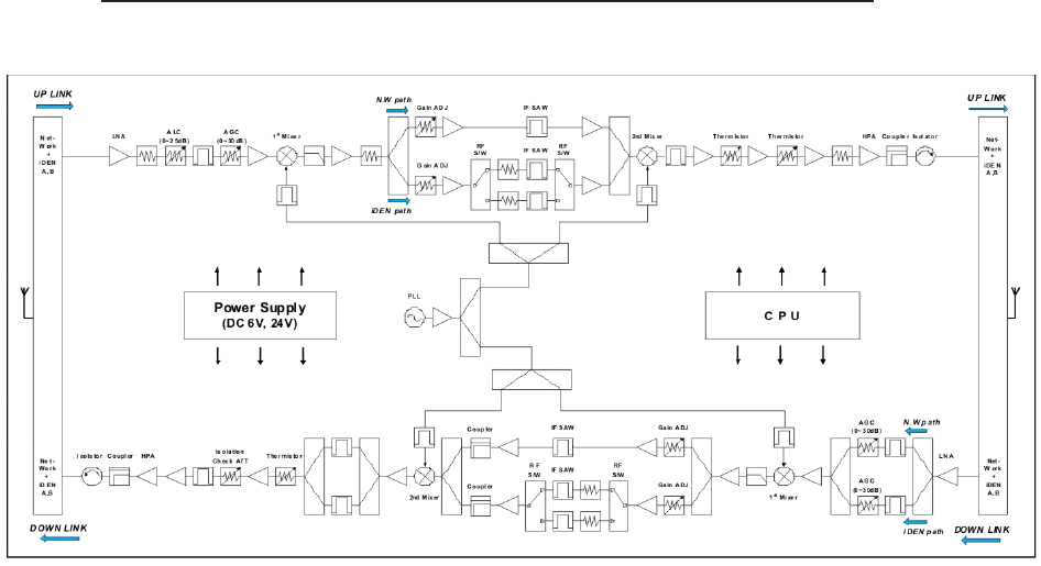
Function Block diagram
The function of the SMR-700/800 is as indicated in the block diagram above.
•Multiplexer Block: combines several different frequencies into one or divides several
different frequencies, combines and transfers the Network and iDEN A, or iDEN B, and
transfers the DL and UL signal separately.
•LNA/AGC Block: Amplifies the low end signal coming from the antenna while
minimizing noise.
•Up/Down Converter Block: Made up of a Mixer and an IF SAW Filter. It converts
frequencies to different frequencies that utilize better filter performance.
•HPA/DRV AMP Block: A power amplifier for the repeater’s high output, high gain and
high linearity.
•PLL Block: Localizes signal for Up/Down converting.
•CPU Block: Controls all repeater functions
•PSU Block: Power supply receiving 110AC volts and converting it to +24VDC and +6VDC.

- 4 -
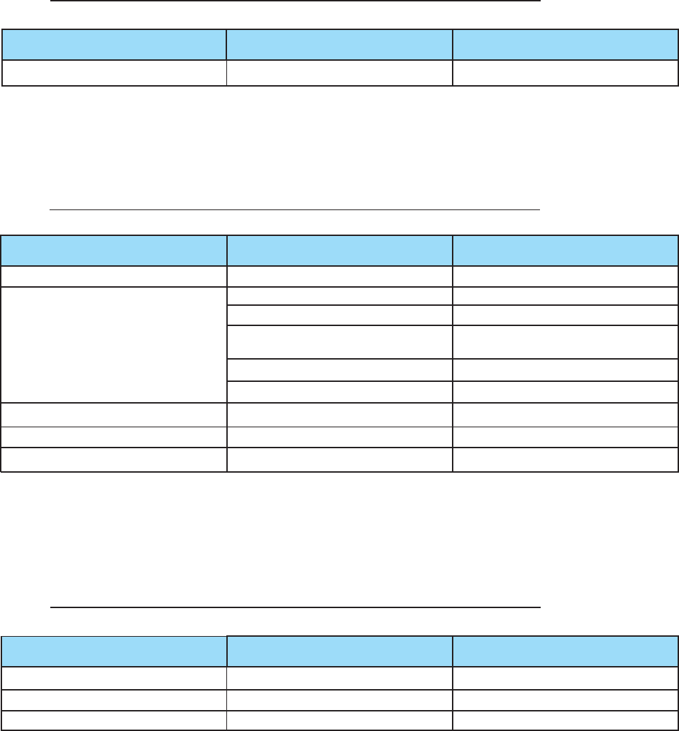
Product Specification
RF Specification
Item Specification
793-805MHz
UL 806-816MHz Sub-Band1
817-824MHz Sub-Band2
FREQ. RANGE 763-775MHz
DL 851-861MHz Sub-Band1
862-869 MHz Sub-Band2
Sub Band Tuning UL / DL 50KHz Step Size (From edge of Pass Band)
Frequency Selectivity UL / DL @-40dBc _2MHz
Gain UL / DL 80dB( _1.0dB)
Sub Band Balance UL / DL _1.0dB
Gain Adjustment Range UL / DL 30dB / 30dB( _1dB, 1dB Step)
ALC Range UL / DL 25dB / 25dB( _1dB)
Pass Band Ripple UL / DL _1.5dB(Peak-To-Peak 3dB)
Linear Output Power UL / DL +27dBm
3rd Order Intercept Point UL / DL +42.5dBm
1dB Gain Compression UL / DL 31dBm
Input VSWR UL / DL <2:1
Max Power Input w/o Damage UL / DL +10dBm
Propagation Delay UL / DL 3us
Noise Figure UL / DL <6.5dB @Max. Gain
+
+
+
+
+
+
- 5 -
Main Power Input Voltage 110VAC @ 1.3A Internal AD DC Power Supply
Power Specification
Size (mm) 200 x 270 x 86.5mm(L x H x D)
Link/Service Antenna Ports N - Female
AC Power In AC Cord 1.5M
Connectors Frame Ground External grounding point to be
provided
RS232C (Internal) 9P D-SUB, female
Alarm (External) 9P D-SUB, female
Mounting Type Wall Mounting with 4 holes 2 holes on each side
Enclosure Lock Key Lock
Heat Dissipation Natural Convection
Mechanical Specification
Operating Temperature -10 C ~ +50 C (ambient) +14 - +122F
Storage Temperature -30 C ~ +55 C (ambient) -22 - +130F
Humidity 95%
Environmental Specification
o
Parameters Specifications Remarks
Parameters Specifications Remarks
Parameter Specifications Remarks
o
oo
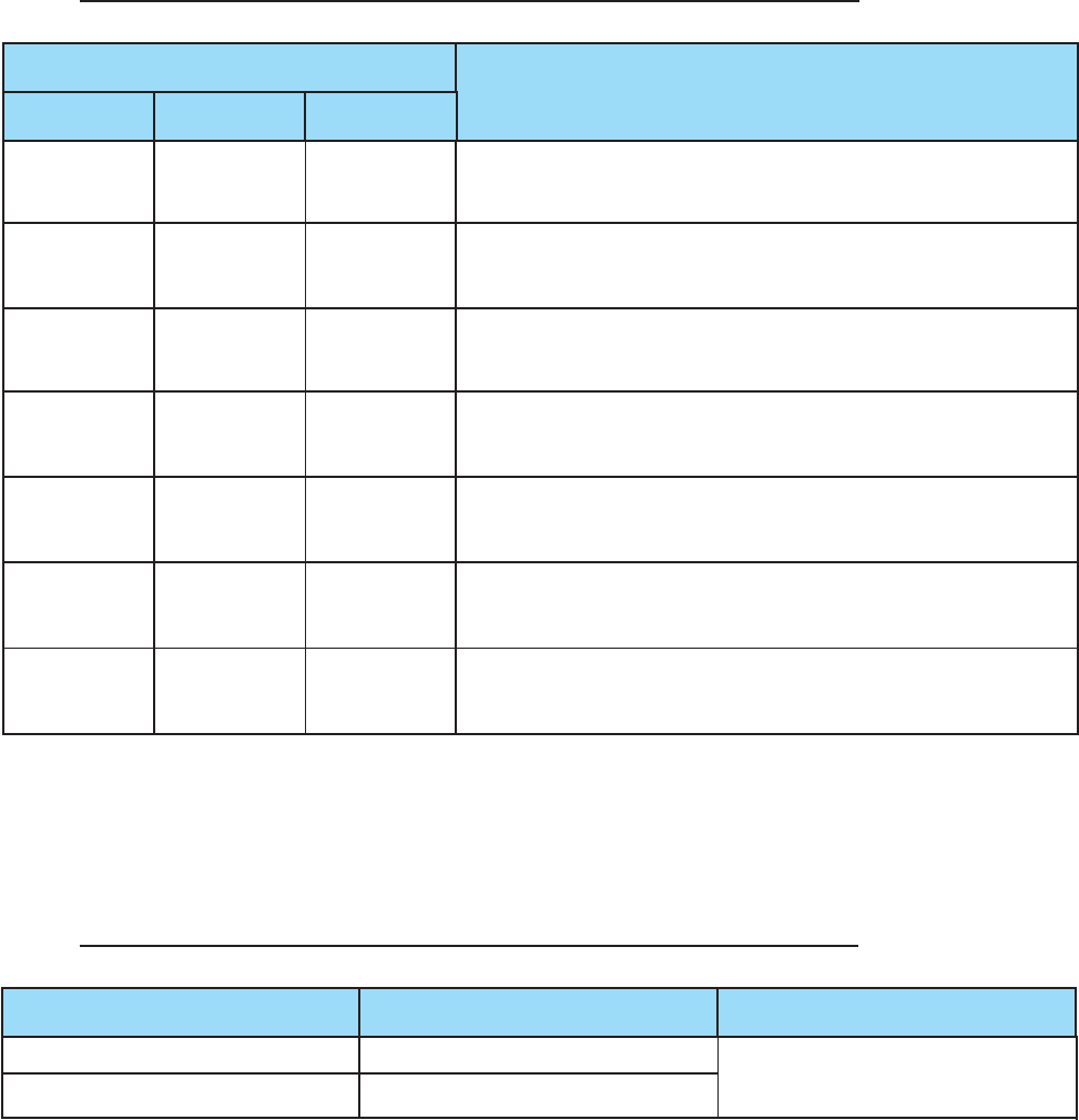
Power Supply is malfunctioning
XXX
(inside repeater)
Blinking Blinking Blinking Checking Isolation Status
GREEN RED RED
Solid Off Off Normal Condition at Start up
GREEN RED RED
Solid Off Off Insufficient distance (Isolation) exists between the DL
and UL Antennae. Remove power and re-install the DL
GREEN RED RED and UL Antennae to correct isolation problem.
Solid Off Solid This condition is the Shut-Down Alarm: signal received
from cell tower is too strong (more than AGC range).
GREEN RED RED Relocate DL antenna to reduce received signal strength.
Solid Off Blinking PLL Lock Detected Failure Alarm.
GREEN RED RED
Blinking Off Off Repeater is non-functional. Contact
Customer Service Center.
GREEN RED RED
Alarm Interface
High NO + CC 1 NC, 2 NO, 3 CC
Low NC + CC
Alarm Relay
- 6 -
Repeater Unit LED Condition / Troubleshooting
Power ISO Alarm
Shutdown Signal Relay Status Remarks
- 7 -
Product Appearance
External Arrangement
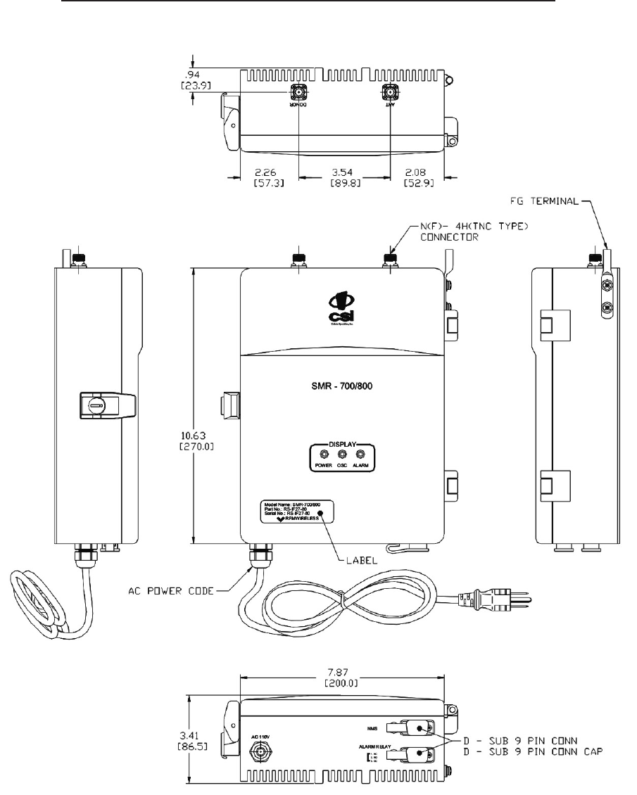
Outline Drawing
- 8 -
- 9 -
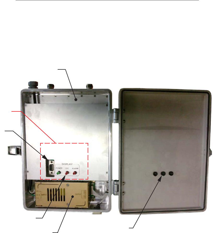
Internal Arrangement
Power supply
GUI Port
Display LED
CPU Board
LED Holder
RF Board
- 10 -
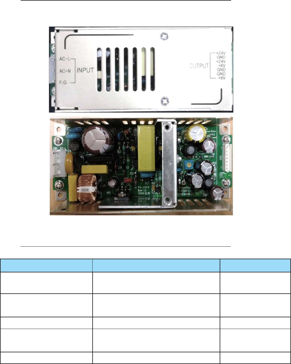
Power Supply Unit (PSU)
The PSU converts the 110VAC line voltage to +24VDC and +6VDC
Normal operation @ 90VAC ~ 140VAC < output
Line Regulation Voltage + 3%
Normal operation @ 24V 2A, 6V 2A
Load Regulation < output Voltage + 3%
Short Current Protection A decline in output voltage will be normalized
< 24V/100mVp-p
Ripple and Noise < 6V/50mVp-p
Efficiency > 70%
Power Supply Specification
Item Specifications Remarks
The unit’s Power Supply
- 11 -
GUI (Graphic User Interface)
Program Introduction
This program checks and controls the operation of the control board for the SMR-700/
800. This program will be communicated via the control board and RS-232C Port.
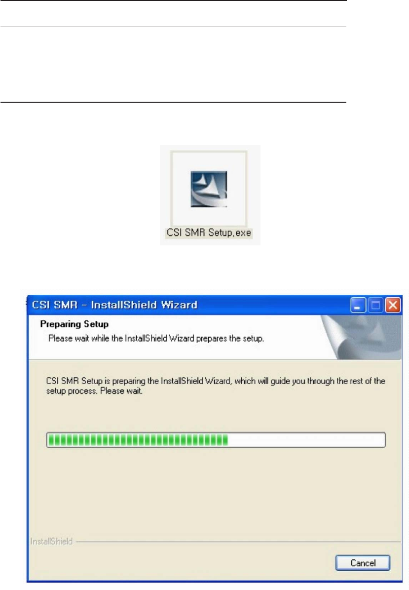
GUI Setup
Begin the installation of the program with the file “CSI SMR Setup.exe”.
Figure 1: Application program installation
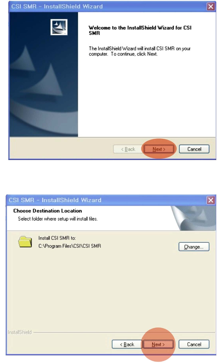
Figure 2: Program installation application
When the screen in Figure 2 appears, Click “Next”
Decide which folder you wish to download into, then click “Next”.
Figure 3: Program installation application
- 12 -
- 13 -
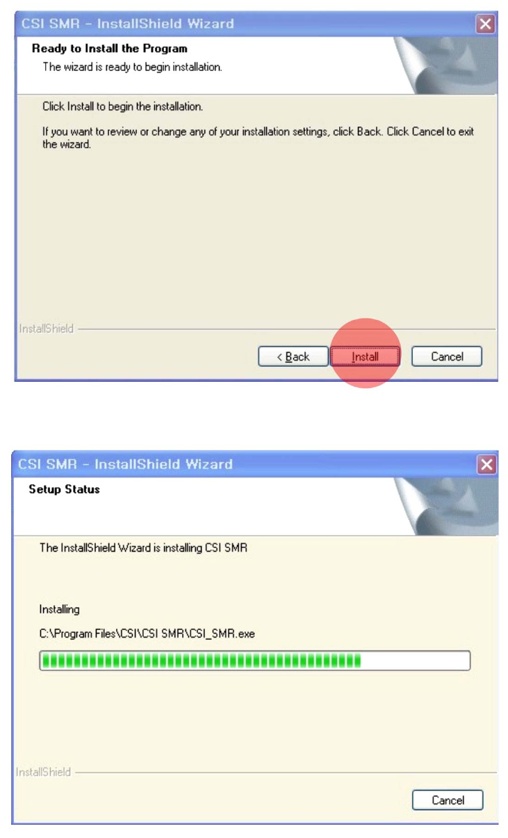
Figure 4: Program installation application
When ready to install program, click “Install”.
Figure 5: Ongoing program installation application
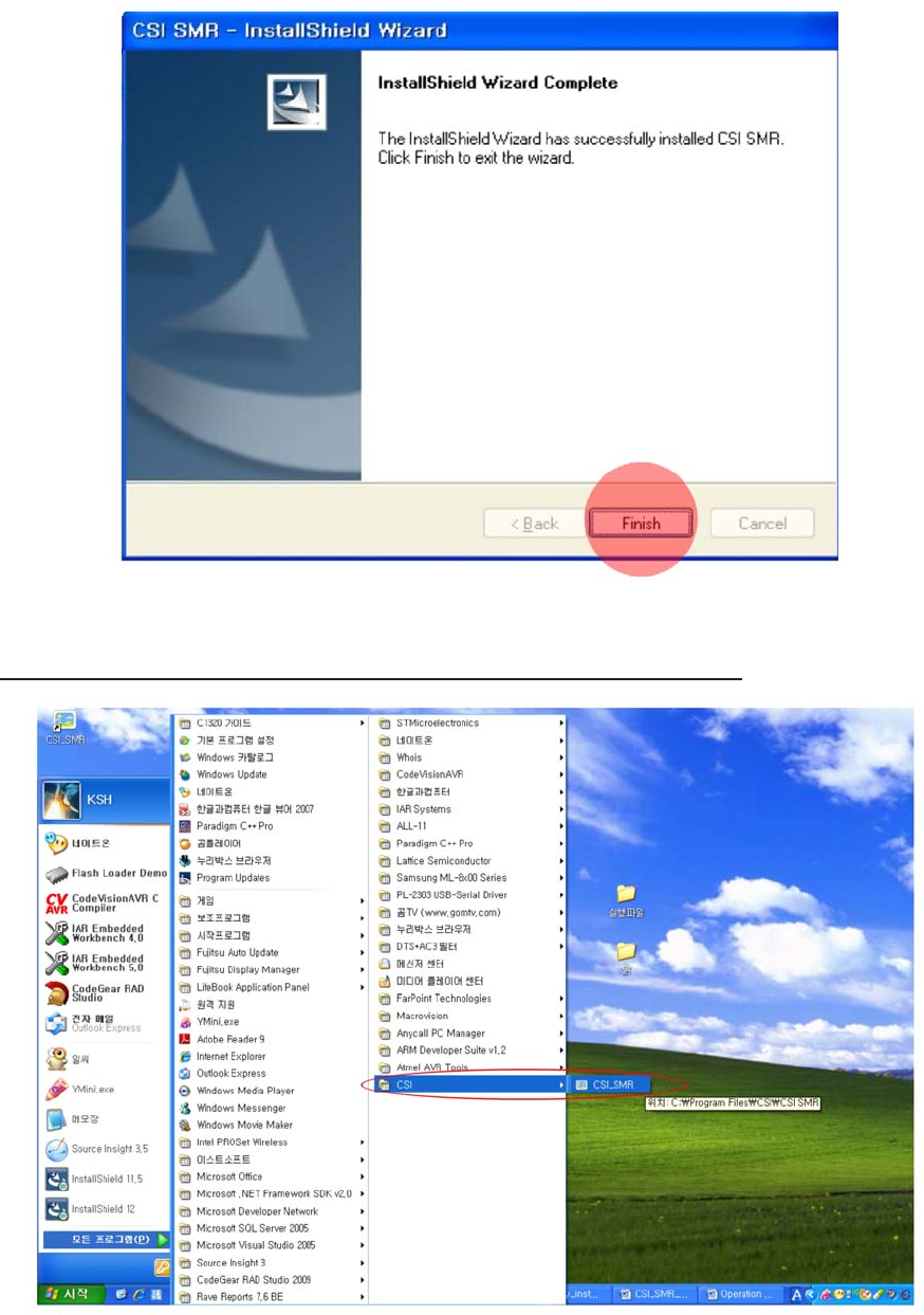
Figure 6: Program installation complete screen
Click “Finish” when setup is complete
Run Program(CSI_SMR.exe)
You should see the CSI Icon listed on your startup menu as seen above.
- 14 -
- 15 -
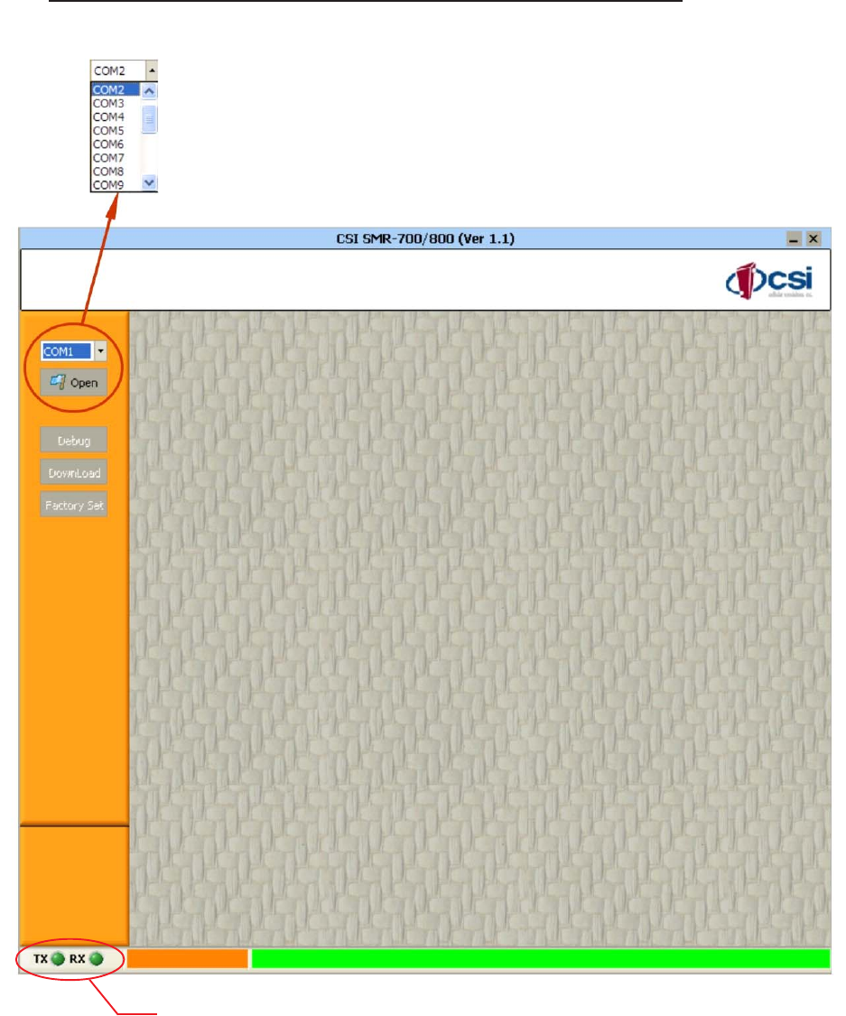
Open Serial Communication Port
Select communication port on your PC, then
press “OPEN” to enable communication with repeater.
Indicates the status of communication with the repeater.
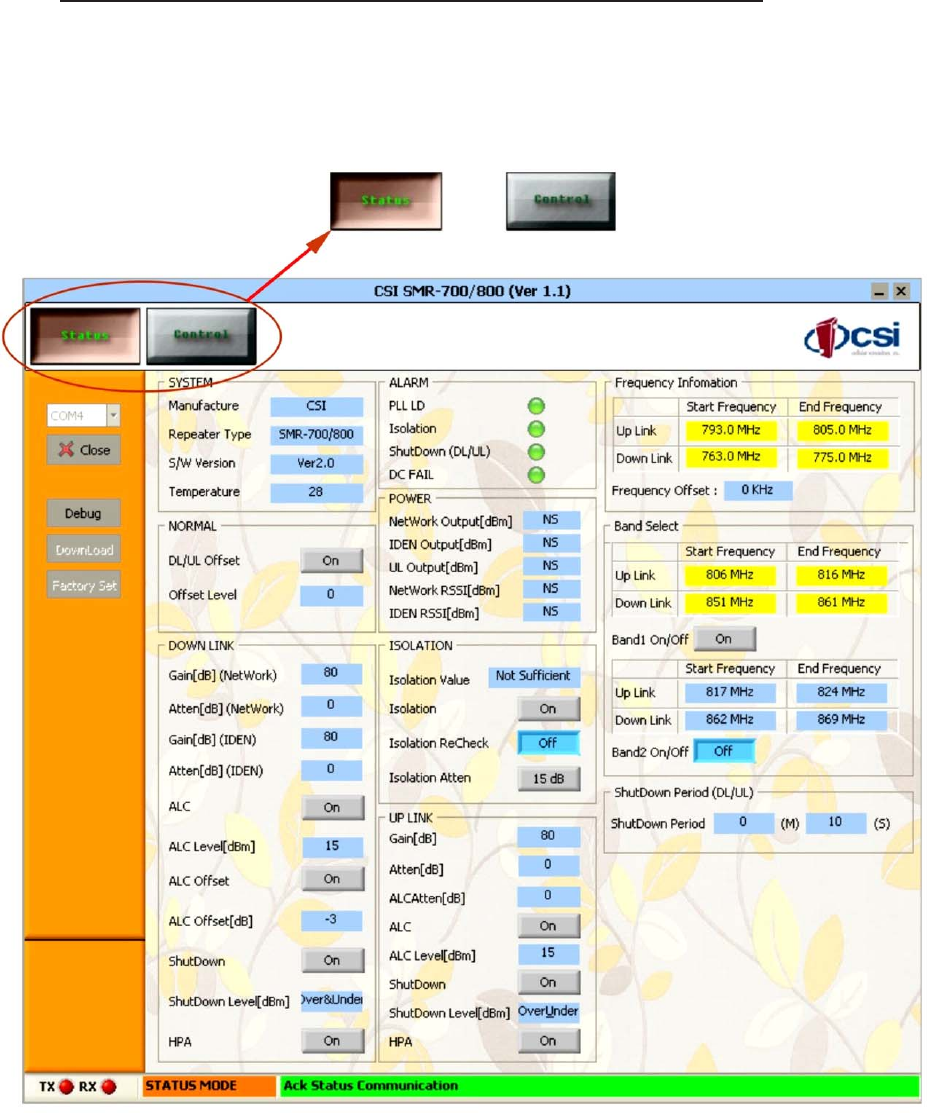
Checking status and control of the SMR-700/800 unit
This screen indicates repeater status and control. You may check each by clinking on the
control buttons shown below
<Status Mode> <Control Mode>
- 16 -
- 17 -
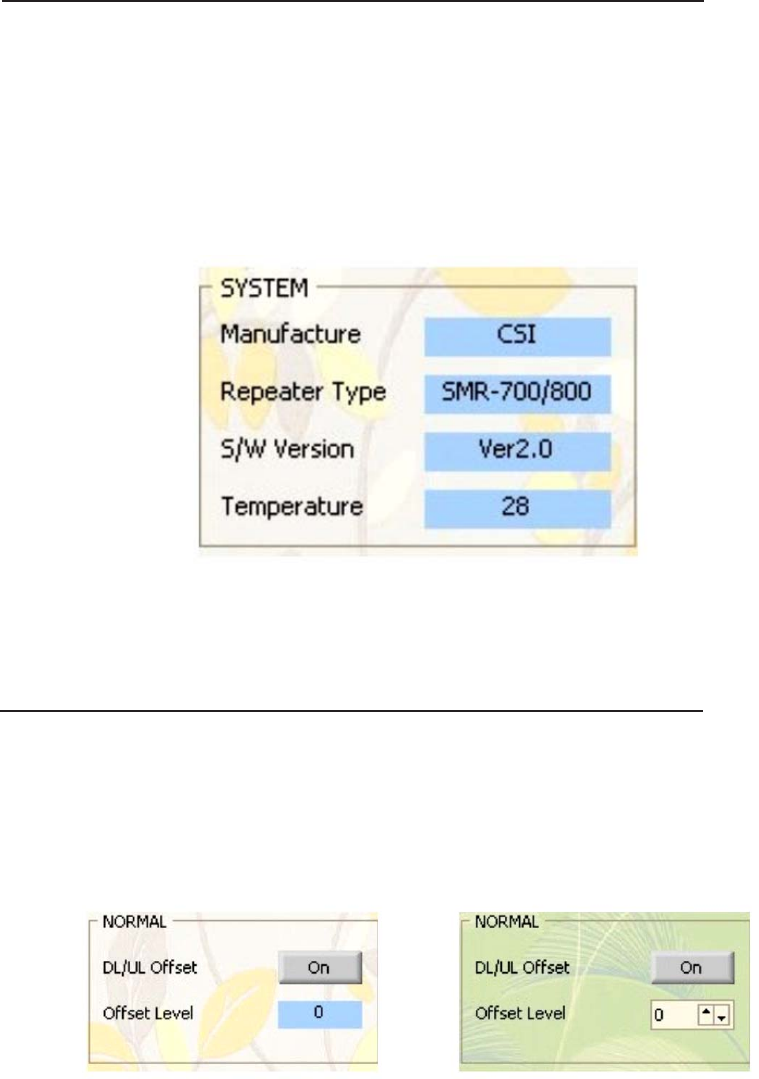
System Status Mode
•Manufacture: Indicates the repeater’s manufacturer
•Repeater Type: Indicates the model of repeater
•S/W Version: Indicates the Firmware version of the control board
•Temperature: Indicates the inner temperature of repeater
Note: The SYSTEM pull-down menu is not part of the Control Menu.
Normal Mode
The System Status screen
•DL/UL Offset: Controls the power level of the Uplink based on the Downlink
power level.(On/Off)
•Offset Level: Controls the Uplink power level based on the Downlink power
level and displays the difference between the two.
Status Mode Control Mode
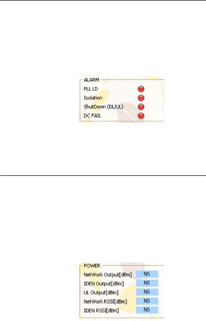
Alarm Status Mode
•PLL LD: Display Alarm (GREEN = Normal; RED = Alarm)
•Isolation: Display Alarm (GREEN = Normal; RED = Alarm)
•ShutDown(DL/UL): Display Alarm (GREEN = Normal; RED = Alarm)
•DC FAIL: Display Alarm (GREEN = Normal; RED = Alarm)
Note: The Alarm pull-down menu is not part of the Control Menu.
Power Status Mode
•NetWork Output(dBm): Displays Downlink output (NetWork).
•iDEN Output(dBm): Displays Downlink output (iDEN).
•UL Output(dBm): Displays Uplink output
•Network RSSI(dBm): Displays the Downlink output (NetWork).
•iDEN RSSI(dBm): Displays the Downlink input (iDEN).
Note: The POWER pull-down menu is not part of the Control Menu.
Alarm status Mode screen
Power status Mode screen
- 18 -
- 19 -
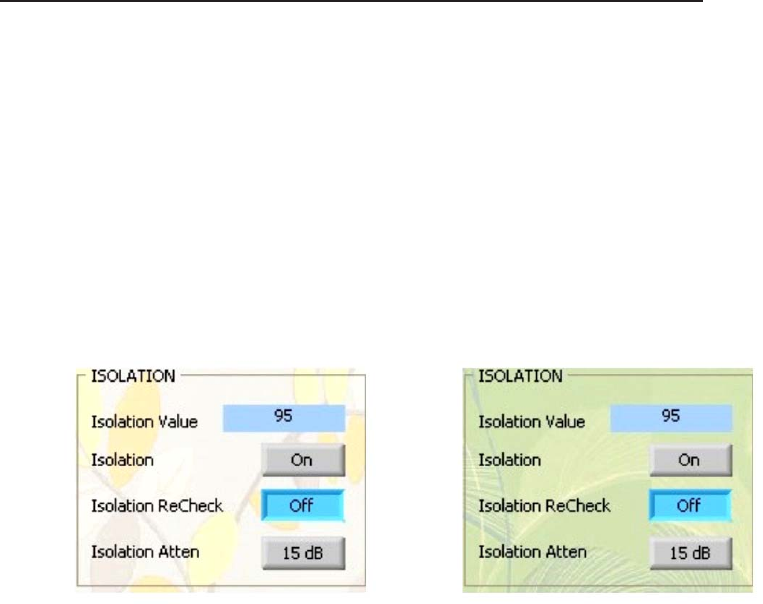
Isolation Status Mode
•Isolation Value: When power is on, an Isolation check is performed, and the values displayed.
•Isolation: The Isolation check can be performed with the power on or off.
•Isolation Recheck: Checks Isolation without the power on.
•Isolation Attenuation: This allows control of the Isolation attenuation.
Note: Neither the Isolation Check or Recheck will not indicate a change in power levels if
the unit’s own power has been switched off.
Isolation status Mode screen Isolation Control Mode screen
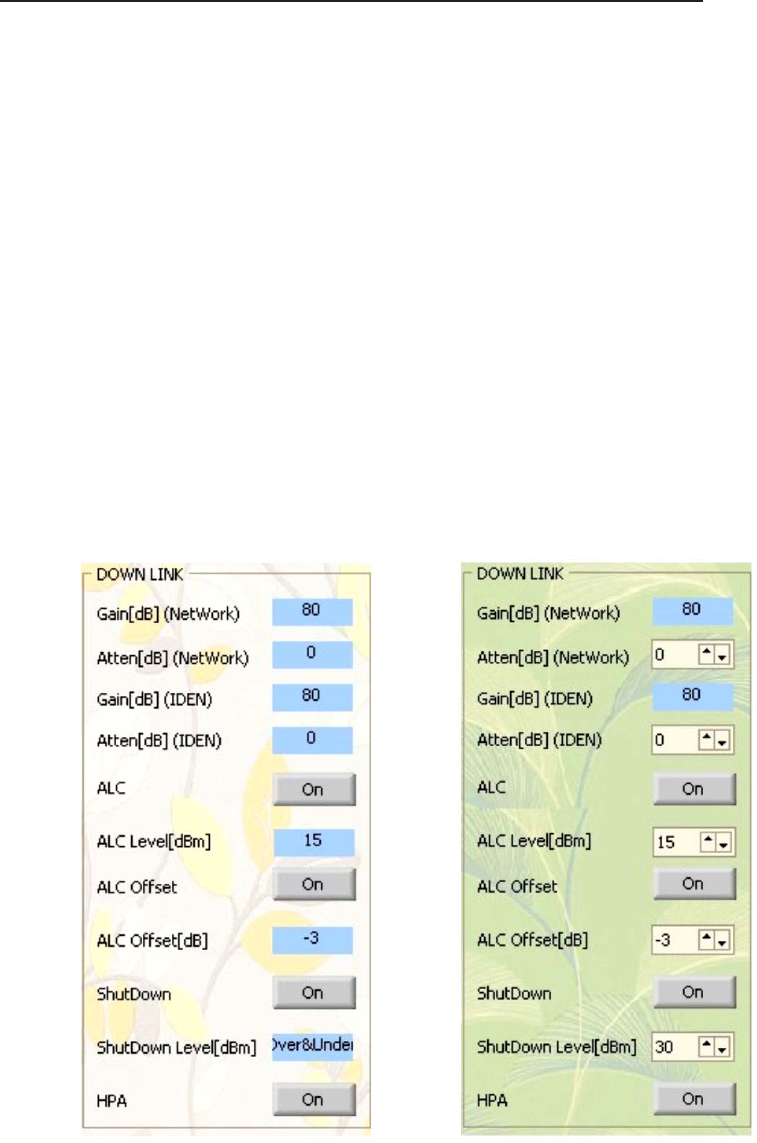
Downlink
•Gain[dB](NetWork): Displays the NetWork Downlink Gain.
•Atten[dB](NetWork): Displays the NetWork Downlink Attenuation value.
•Gain[dB](iDEN): Displays the iDEN Downlink Gain.
•Atten[dB](iDEN): Displays the iDEN Downlink Attenuation value.
•ALC: This allows the user to toggle the Auto Level Control function on or off.
•ALC Level[dBm]: Sets the unit’s maximum ALC output value.
•ALC Offset: This allows the user to toggle the Auto Level Control Offset on or off.
•ALC Offset[dB]: Sets the unit’s minimum ALC output value.
•Shutdown: This allows the user to shutdown the unit if the downlink output is higher
than the user determined shutdown value.
•Shutdown Level: This allows the user to input the maximum value at which the
unit will shutdown.
•HPA: This allows the user to toggle the Downlink HPA on or off.
Downlink Status Mode Downlink Control Mode
- 20 -
- 21 -
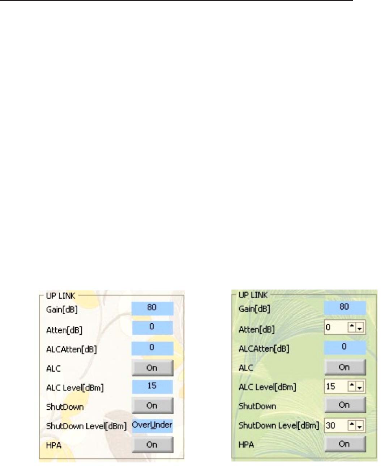
Uplink
•Gain[dB]: Displays the status of the Uplink Gain.
•Atten[dB]: Displays the Uplink Attenuation value.
•ALC Atten[dB]: Displays the attenuation value of a strong signal in the initial stage when
unit is powered (Control unavailable).
•ALC: This allows the user to toggle the Auto Level Control function on or off.
•ALC Level[dBm]: Sets the unit’s maximum ALC output value.
•Shutdown: This allows the user to toggle the HPA shutdown of the unit if the Downlink
output is higher than the user determined shutdown value.
•Shutdown Level: This allows the user to input the maximum value at which the
unit will shutdown.
•HPA: This allows the user to toggle the Uplink HPA on or off.
Uplink Status Mode Uplink Control Mode
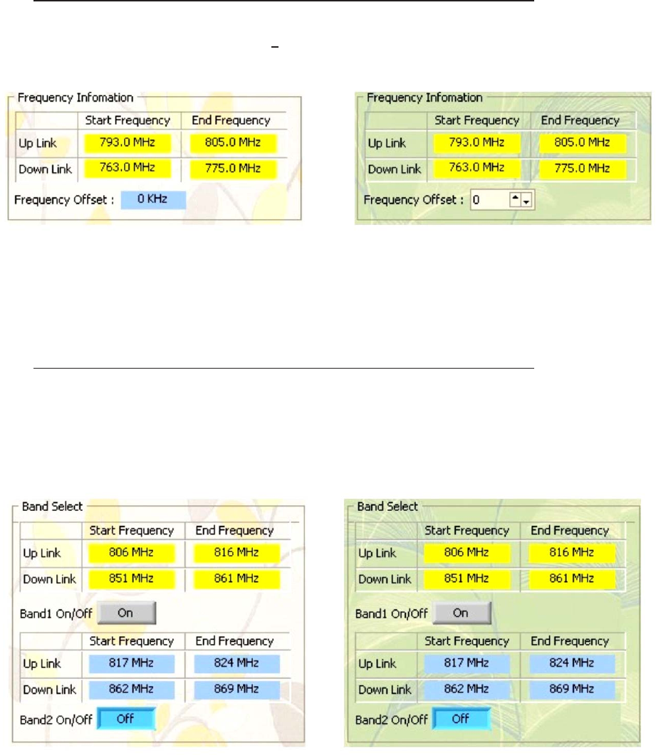
Frequency Information
Frequency offset: 931.300 MHz + 1 MHz (50 KHz Steps).
Frequency Status Mode Frequency Control Mode
Band Select
•Band 1 On/Off: Activates Band 1 Frequency (Band 2 is deactivated).
•Band 2 On/Off: Activates Band 2 Frequency (Band 1 is deactivated).
Band Select Status Mode Band Select Control Mode
- 22 -
- 23 -
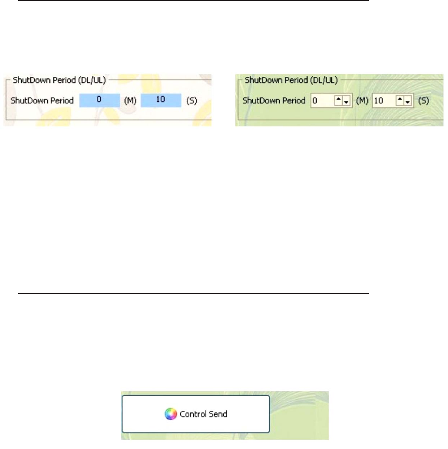
Shutdown Period
Shutdown Period (M),(S): Allows the user to set the shutdown period duration.
Shutdown Status Mode Shutdown Control Mode
Control Send
Control Send: When the unit is fully configured, the settings can then be sent to the
repeater by clicking on the “CONTROL SEND” button.
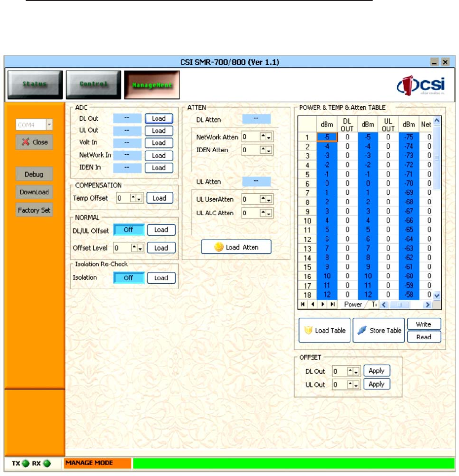
Management Mode
Press Ctrl + F10 while in Mode Status/Control Mode to go into Management Mode
Management Mode Screen
- 24 -
- 25 -
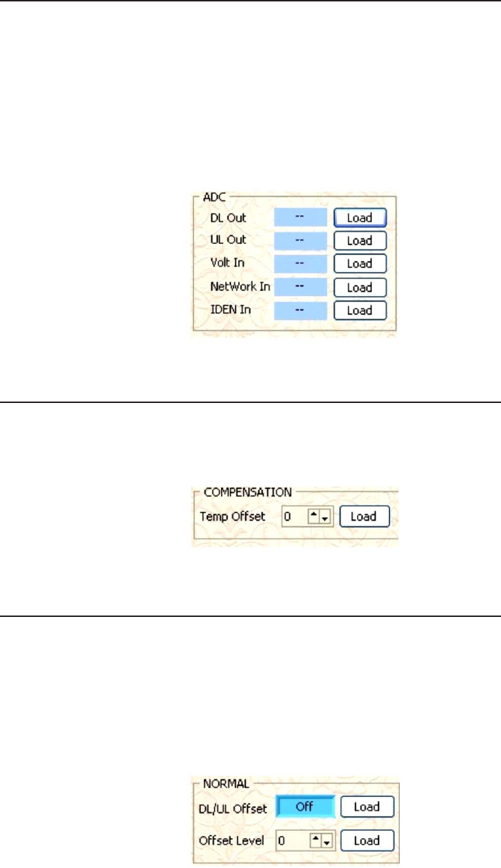
ADC
•DL Out: This displays the updated A/D value of DL Out.
•UL Out: This displays the updated A/D value of UL Out under load.
•Volt In: This displays the updated A/D value of the Input Voltage.
•Network In: This displays the updated A/D value of UL Out under load.
•iDEN In: This displays the updated A/D value of UL Out.
Click the appropriate “LOAD” button to display the following:
Compensation
•Temp Offset: Allows the user to input a value for the repeater temperature offset.
•Load: This displays the temperature offset value.
Normal
•DL /UL Offset: This displays the value of DL /UL Offset.
•Load: This allows the user to toggle the DL/UL Offset display on or off.
•Offset Level: This displays and allows the user to set the value of the offset level.
•Load: This applies the selected offset level to the repeater.
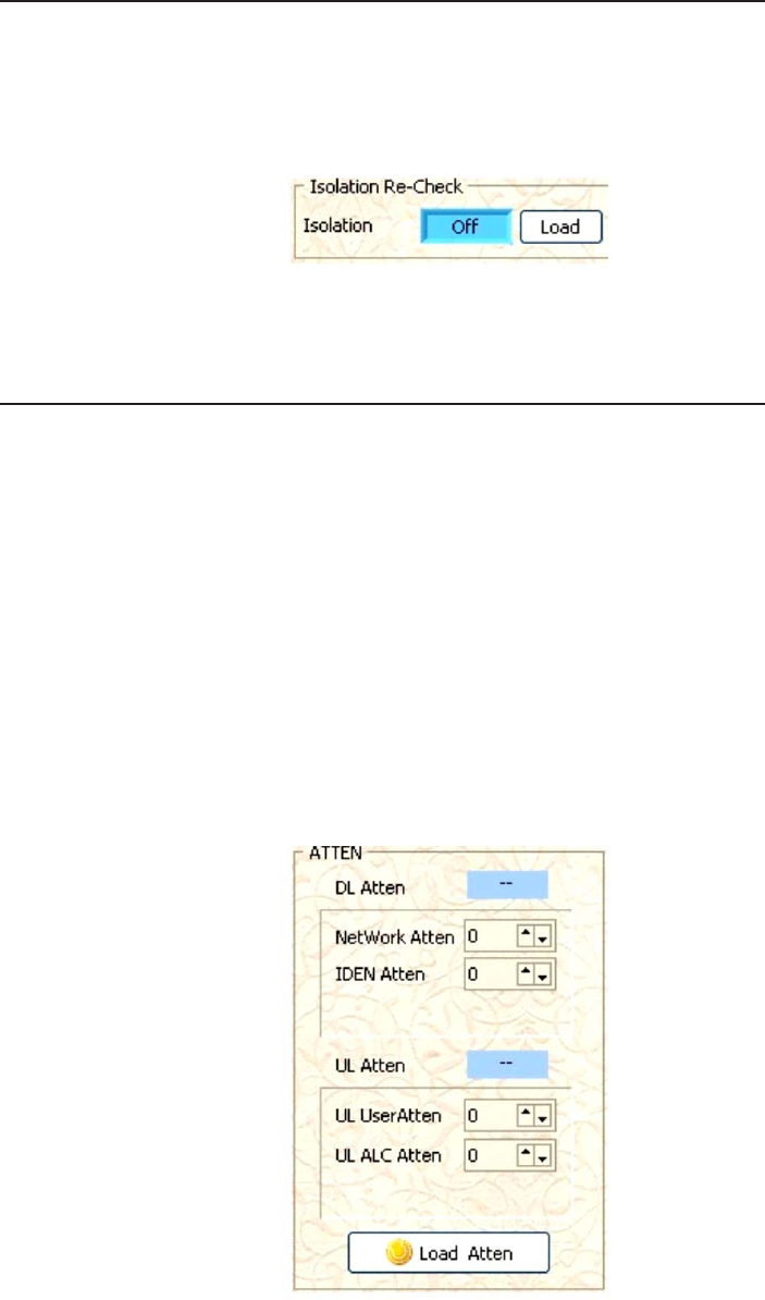
Isolation Re-Check
•Isolation: This displays the status of the Isolation Re-Check function.
•Load: This allows the user to toggle the Isolation Re-Check function display on or off.
Attenuation
•DL Atten: This displays the attenuation value of the Downlink(NetWork)
•NetWork Atten: This controls & displays the attenuation value of the Downlink(NetWork).
•iDEN Atten: This controls & displays the attenuation value of the Downlink(iDEN).
•UL Atten: This displays the attenuation value of the Uplink.
•User Atten: This controls & displays the attenuation value of the Uplink.
•ALC Atten: This controls & displays the attenuation value of the Uplink ALC.
•Load Atten: This configures the attenuation values in the repeater and updates the
values displayed in the DL Atten & UL Atten windows.
The DL Atten is controlled thru the NetWork Atten and iDEN Atten settings; UL Atten is controlled thru
the User Atten and ALC Atten settings.
- 26 -
- 27 -
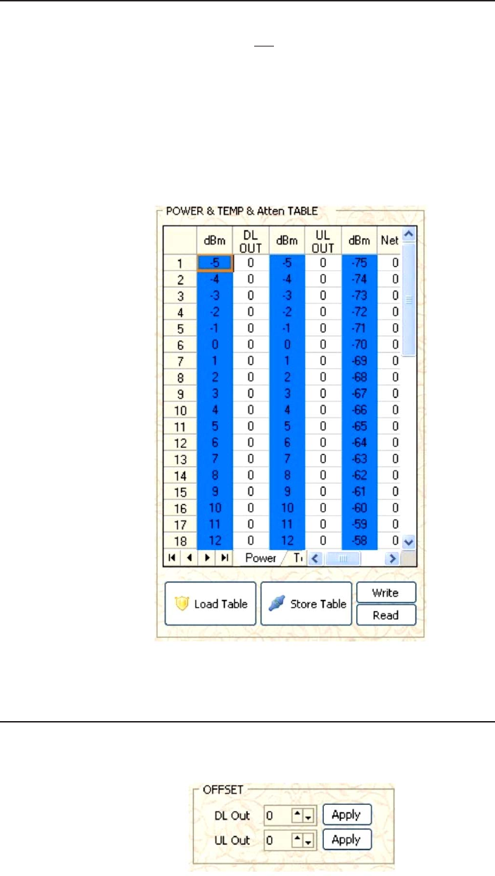
Power & Temp & Atten Table
Apply DL Out value for ISOLATION CHECK operation.
•Load Table: This downloads & displays the applied values from the repeater.
•Store Table: This configures the repeater to user applied values.
•Write: This saves the most current version of the table to a .txt format
•Read: This displays the .txt copy of the table on the screen.
The POWER & TEMP & Atten table displays the applied decibel value for NetWork
RSSI, iDEN RSSI, & UL Output. It does not display A/D values.
Offset
Configure the unit’s Offset values using the Offset table.
Temp Table and Attenuation Table is not used.
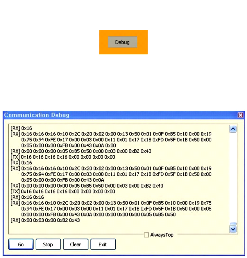
Debugging
To begin the debugging process, click the “Debug” button in management mode.
This allows the user to check the data transferring between the repeater and the PC.
•Go: This displays the comunications contents that have been suspended.
•Stop: This command stops the contents of the communications from scrolling.
•Clear: This deletes all communication contents being displayed.
•Exit: This command closes the debug window.
•Always Top: This sets the debug window to always display at the top of the window.
- 28 -
- 29 -
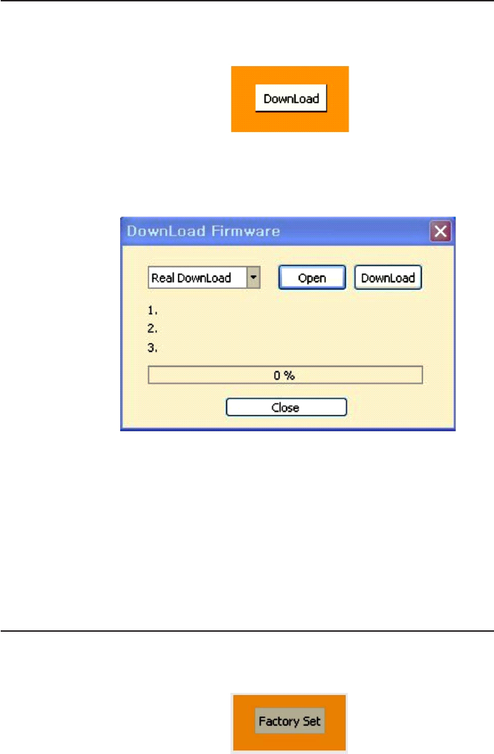
Downloading
To update the firmware, begin by clicking the “Download” button in management mode.
•Click Open: Open the firmware binary file. The Binary File Open dialog box will open.
•Download: Firmware download status will be displayed. The Download Complete
message will open when the procedure is complete or an error message will
be displayed. Write the firmware file to the repeater.
•Close: This command closes the download window.
•This feature is currently not used.
•Feature will be included in the next production run.
Next, perform the following steps:
Factory Settings
Click on the “Factory Set” button in Management Mode.
- 30 -

- 31 -
One Year Limited Warranty
Seller warrants that its products are transferred rightfully and with good title;
that its products are free from any lawful security interest or other lien or
encumbrance unknown to Buyer; and that for a period of one year from the
date of installation or fifteen months from the date of original shipment, which-
ever period expires first, such products will be free from defects in material and
workmanship which arise under proper and normal use and service. Buyer’s
exclusive remedy hereunder is limited to Seller’s correction (either at its plant
or at such other place as may be agreed upon between Seller and Buyer) of
such defects by repair or replacement at no cost to Buyer. Transportation costs
in connection with the return of products to Seller’s plant or designated facility
shall be paid by Buyer. The provisions of this warranty shall be applicable with
respect to any product which Seller replaces pursuant to it. SELLER MAKES
NO WARRANTY, EXPRESS OR IMPLIED, OTHER THAN AS SPECIFICALLY
STATED ABOVE. EXPRESSLY EXCLUDED ARE THE IMPLIED WARRANTIES
OF MERCHANTABILITY AND FITNESS FOR PURPOSE. THE FOREGOING
SHALL CONSTITUTE ALL OF SELLER’S LIABILITY (EXCEPT AS TO PATENT
INFRINGEMENT) WITH RESPECT TO THE PRODUCTS. IN NO EVENT
SHALL SELLER BE LIABLE FOR SPECIAL, CONSEQUENTIAL OR INCIDEN-
TAL DAMAGES, INSTALLATION COSTS, LOST REVENUE OR PROFITS, OR
ANY OTHER COSTS OF ANY NATURE AS A RESULT OF THE USE OF
PRODUCTS MANUFACTURED BY THE SELLER, WHETHER USED IN
ACCORDANCE WITH INSTRUCTIONS OR NOT. UNDER NO CIRCUM-
STANCES SHALL SELLER’S LIABILITY TO BUYER EXCEED THE ACTUAL
SALES PRICE OF THE PRODUCTS PROVIDED HEREUNDER. No represen-
tative is authorized to assume for Seller any other liability in connection with
the products.
Industry Certifications/Registration Numbers:
FCC ID: NVRCSI-T51080-SP78

D960-1048-001 rev002