Westell D90327W30-XX 802.11g wireless router User Manual User Guide Rev 1
Westell Inc 802.11g wireless router User Guide Rev 1
Westell >
Manual abridged
Not e t ha t the sections highlighted in the index have been removed t o ke e p t he file size be lo w
4Mb. These pages deal with the confiugration of the DSL and wired ethernet internets. No
information relating to the wireless interface were contained in the deleted pages.

030-300452 Rev. A BellSouthVersaLinkGateway
3/6/06 – Draft 5
Copyright © 2005 Westell, Inc. 030-300452 Rev. A
Draft 4 updates section 3.1, FCC Compliance Note.
Draft 5 updates the text in Figure 1 and Table 2 for snap-in wireless antenna
VERSALINK™ GATEWAY (MODEL 327W)
USER GUIDE

030-300452 Rev. A
BellSouthVersaLinkGateway
3/6/06 – Draft 5
030-300452 Rev. A ii March 2006
VersaLink Gateway (Model 327W)
User Guide
CONTENTS
1. PRODUCT DESCRIPTION ..................................................................................................................................1
2. SAFETY INSTRUCTIONS ...................................................................................................................................1
3. REGULATORY INFORMATION ........................................................................................................................2
3.1 FCC Compliance Note................................................................................................................................2
3.2 Canada Certification Notice .......................................................................................................................3
4. SYSTEM REQUIREMENTS.................................................................................................................................5
5. HARDWARE FEATURES....................................................................................................................................6
5.1 LED Indicators ...........................................................................................................................................6
5.2 Rear Panel Features ....................................................................................................................................8
6. CUSTOMER INFORMATION ...........................................................................................................................10
6.1 Confirming Your DSL Sync.....................................................................................................................10
6.2 Setting Up Customer Information ............................................................................................................10
6.3 Establishing Your PPP Session ................................................................................................................13
7. MACINTOSH OS X ............................................................................................................................................15
8. CONFIGURING VERSALINK...........................................................................................................................20
9. HOME SUMMARY.............................................................................................................................................21
9.1 Easy Login................................................................................................................................................22
9.2 Modem Self Test ......................................................................................................................................26
9.3 Remote Access .........................................................................................................................................27
9.4 Update Modem .........................................................................................................................................29
9.5 Reset Modem............................................................................................................................................49
10. BROADBAND DSL LINE ..................................................................................................................................51
10.1 Configure Connection...............................................................................................................................52
10.2 Remote Access .........................................................................................................................................60
10.3 Statistics....................................................................................................................................................62
10.4 WAN ........................................................................................................................................................66
10.5 Route ........................................................................................................................................................78
10.6 RIP............................................................................................................................................................80
10.7 Logs..........................................................................................................................................................82
11. HOME NETWORK .............................................................................................................................................85
11.1 Private LAN..............................................................................................................................................86
11.2 IP Passthrough/DMZ – Single Static IP Address Passthrough.................................................................88
11.3 NAT/Gaming............................................................................................................................................94
11.4 QoS.........................................................................................................................................................105
11.5 VLAN.....................................................................................................................................................114
11.6 Statistics..................................................................................................................................................117
12. WIRELESS ........................................................................................................................................................121
12.1 Configuration..........................................................................................................................................123
12.2 Statistics..................................................................................................................................................129
13. FIREWALL AND PASSWORDS .....................................................................................................................131
13.1 Security Level/Remote Logging.............................................................................................................133
13.2 IP Passthrough/DMZ – Single IP Address Passthrough.........................................................................138
13.3 NAT/GAMING ......................................................................................................................................139
13.4 Password/User Admin ............................................................................................................................140

030-300452 Rev. A
BellSouthVersaLinkGateway
3/6/06 – Draft 5
030-300452 Rev. A iii March 2006
VersaLink Gateway (Model 327W)
User Guide
13.5 Firewall Log ...........................................................................................................................................141
14. DIAGNOSTICS .................................................................................................................................................144
14.1 Full Diagnostics......................................................................................................................................145
14.2 IP Tests...................................................................................................................................................147
14.3 Logs........................................................................................................................................................152
15. NAT Services .....................................................................................................................................................154
16. APPENDIX A: TROUBLESHOOTING CONNECTION FAILURES.............................................................158
16.1 Login Failed at Customer Information ...................................................................................................158
16.2 Login Failed at Easy Login Page............................................................................................................159
16.3 DSL Connection is Down.......................................................................................................................160
16.4 ATM Connection is Down .....................................................................................................................162
16.5 Cannot Connect to Target Internet Service Provider..............................................................................163
17. APPENDIX B: CONFIGURING THE WAN PORT.........................................................................................164
17.1 Disabling DSLATM PORT – Enabling ETHERNET PORT 1 ..............................................................165
17.2 Enabling DSLATM PORT – Disabling ETHERNET PORT 1 ..............................................................167
18. PRODUCT SPECIFICATIONS.........................................................................................................................170
19. SOFTWARE LICENSE AGREEMENT............................................................................................................171
20. PUBLICATION INFORMATION.....................................................................................................................173
030-300452 Rev. A
BellSouthVersaLinkGateway
3/6/06 – Draft 5
030-300452 Rev. A 1 March 2006
VersaLink Gateway (Model 327W)
User Guide
1. PRODUCT DESCRIPTION
Westell’s VersaLink™ Gateway adds reliable, high-speed, Internet access to your existing home or office phone
line. Your DSL connection ends the hassles of dial-up modems and busy signals. Installation is easy ... no tools ... no
headaches. Simply plug the VersaLink™ Gateway into the 10/100 Base-T port of your PC, apply power, perform
the simple software configuration, and connect your DSL phone line to the VersaLink™ Gateway.
This modem is capable of data rates hundreds of times faster than a traditional analog modem. But unlike analog
modems, Westell’s VersaLink™ Gateway allows you to use the same phone line for simultaneous voice/fax
communications and high-speed Internet access, eliminating the need for dedicated phone lines for voice and data
needs. The Plug and Play feature means that no user configuration is required.
NOTE: Hereafter, the Westell VersaLink™ Gateway will be referred to as the “VersaLink” or the “Modem.”
2. SAFETY INSTRUCTIONS
¾ Never install any telephone wiring during a lightning storm.
¾ Never install telephone jacks in wet locations unless the jack is specifically designed for wet locations.
¾ Never touch non-insulated telephone wires or terminals unless the telephone line has been disconnected at the
network interface.
¾Use caution when installing or modifying telephone lines.
WARNING
Risk of electric shock. Voltages up to 140 Vdc (with reference to ground) may be present on
telecommunications circuits.

030-300452 Rev. A
BellSouthVersaLinkGateway
3/6/06 – Draft 5
030-300452 Rev. A 2 March 2006
VersaLink Gateway (Model 327W)
User Guide
3. REGULATORY INFORMATION
This section details the FCC, compliance registration, and Canada certification notice for the VersaLink™ Gateway.
3.1 FCC Compliance Note
(FCC ID: CH8D90327W30-XX)
This equipment has been tested and found to comply with the limits for a Class B digital device, pursuant to Part 15
of the Federal Communication Commission (FCC) Rules. These limits are designed to provide reasonable protection
against harmful interference in a residential installation. This equipment generates, uses, and can radiate radio
frequency energy, and if not installed and used in accordance with the instructions, may cause harmful interference
to radio communications. However, there is no guarantee that interference will not occur in a particular installation.
If this equipment does cause harmful interference to radio or television reception, which can be determined by
turning the equipment OFF and ON, the user is encouraged to try to correct the interference by one or more of the
following measures:
x Reorient or relocate the receiving antenna.
x Increase the separation between the equipment and the receiver.
x Connect the equipment to a different circuit from that to which the receiver is connected.
x Consult the dealer or an experienced radio/TV technician for help.
x This device complies with part 15 of the FCC Rules. Operation is subject to the following two conditions:
(1) This device may not cause harmful interference, and (2) this device must accept any interference
received, including interference that may cause undesired operation.
WARNING: While this device is in operation, a separation distance of at least 20 cm (8 inches) must be maintained
between the radiating antenna and users exposed to the transmitter in order to meet the FCC RF exposure guidelines.
Making changes to the antenna or the device is not permitted. Doing so may result in the installed system exceeding
RF exposure requirements. This device must not be co-located or operated in conjunction with any other antenna or
radio transmitter. Installers and end users must follow the installation instructions provided in this guide.
Modifications made to the product, unless expressly approved by Westell Inc., could void the user’s rights to
operate the equipment.
PART 68 - COMPLIANCE REGISTRATION
This equipment (Model 327W) complies with Part 68 of the ACTA rules and the requirements adopted by the
ACTA. A label on the bottom of this equipment contains, among other information, the Ringer Equivalence Number
(REN) and the product identifier. For products approved after July 23, 2001 the product identifier is in the format
US:AAAEQ##TXXXX. The digits represented by ## are the REN without a decimal point (e.g., 03 is a REN of
0.3). The REN is used to determine the number of devices that may be connected to a telephone line. For earlier
products, the REN is separately shown on the label. If requested, this number must be provided to the telephone
company.
Excessive RENs on a telephone line may result in the devices not ringing in response to an incoming call. In most,
but not all areas, the sum of RENs should not exceed five (5.0). To be certain of the number of devices that may be
connected to a line, as determined by the total RENs, contact the local telephone company.

030-300452 Rev. A
BellSouthVersaLinkGateway
3/6/06 – Draft 5
030-300452 Rev. A 3 March 2006
VersaLink Gateway (Model 327W)
User Guide
This equipment is designated to connect to the telephone network or premises wiring using a compatible modular
jack that is Part 68 compliant. An ACTA compliant telephone cord and modular plug is provided with the
equipment. See the Installation Information section of this User Guide for details.
A plug and jack used to connect this equipment to the premises wiring and telephone network must comply with the
applicable ACTA 968-A rules and requirements adopted by the ACTA. A compliant telephone cord and modular
plug is provided with this product. It is designed to be connected to a compatible modular jack that is also
compliant. See installation instruction for details.
If this terminal equipment (Model 327W) causes harm to the telephone network, the telephone company may
request you to disconnect the equipment until the problem is resolved. The telephone company will notify you in
advance if temporary discontinuance of service is required. If advance notification is not practical, the telephone
company will notify you as soon as possible. You will be advised of your right to file a complaint with the ACTA if
you believe such action is necessary. If you experience trouble with this equipment (Model 327W), do not try to
repair the equipment yourself. The equipment cannot be repaired in the field. Contact the BellSouth help desk at 1-
888-321-2DSL (2375) for instructions on product return.
The telephone company may make changes to their facilities, equipment, operations, or procedures that could affect
the operation of this equipment. If this happens, the telephone company will provide advance notice in order for you
to make the modifications necessary to maintain uninterrupted service.
If your home has specially wired alarm equipment connected to the telephone line, ensure that the installation of this
equipment (Model 327W) does not disable your alarm equipment. If you have questions about what will disable
alarm equipment, consult your telephone company or a qualified installer.
This equipment cannot be used on public coin phone service provided by the telephone company. Connection of this
equipment to party line service is subject to state tariffs.
3.2 Canada Certification Notice
The Industry Canada label identifies certified equipment. This certification means that the equipment meets certain
telecommunications network protective, operations and safety requirements as prescribed in the appropriate
Terminal Equipment Technical Requirements document(s). The department does not guarantee that the equipment
will operate to the user’s satisfaction.
This equipment meets the applicable Industry Canada Terminal Equipment Technical Specification. This is
confirmed by the registration number. The abbreviation, IC, before the registration number signifies that registration
was performed based on a Declaration of Conformity indicating that Industry Canada technical specification were
met. It does not imply that Industry Canada approved the equipment. The Ringer Equivalence Number (REN) is 0.0.
The Ringer Equivalence Number that is assigned to each piece of terminal equipment provides an indication of the
maximum number of terminals allowed to be connected to a telephone interface. The termination on an interface
may consist of any combination of devices subject only to the requirement that the sum of the Ringer Equivalence
Numbers of all the devices does not exceed five.
Before installing this equipment, users should ensure that it is permissible to be connected to the facilities of the
local Telecommunication Company. The equipment must also be installed using an acceptable method of
connection. The customer should be aware that compliance with the above conditions may not prevent degradation
of service in some situations. Connection to a party line service is subject to state tariffs. Contact the state public
utility commission, public service commission, or corporation commission for information.
If your home has specially wired alarm equipment connected to the telephone line, ensure that the installation of this
equipment (Model 327W) does not disable your alarm equipment. If you have questions about what will disable
alarm equipment, consult your telephone company or a qualified installer.

030-300452 Rev. A
BellSouthVersaLinkGateway
3/6/06 – Draft 5
030-300452 Rev. A 4 March 2006
VersaLink Gateway (Model 327W)
User Guide
If you experience trouble with this equipment (Model 327W), do not try to repair the equipment yourself. The
equipment cannot be repaired in the field and must be returned to the manufacturer. Repairs to certified equipment
should be coordinated by a representative, and designated by the supplier. Contact Westell Technical Support at
telephone no. (630) 375-4500 for instructions on product return.
The termination on an interface may consist of any combination of devices subject only to the requirement that the
sum of the Ringer Equivalence Numbers of all the devices does not exceed five.
Users should ensure, for their own protection, that the electrical ground connections of the power utility, telephone
lines, and internal, metallic water pipe system, if present, are connected together. This precaution may be
particularly important in rural areas.
CAUTION
Users should not attempt to make such connections themselves, but should contact the appropriate electrical
inspection authority, or electrician, as appropriate.

030-300452 Rev. A
BellSouthVersaLinkGateway
3/6/06 – Draft 5
030-300452 Rev. A 5 March 2006
VersaLink Gateway (Model 327W)
User Guide
4. SYSTEM REQUIREMENTS
The following system specifications are required for optimum performance of the VersaLink™ Gateway via 10/100
Base-T and Wireless installation.
CONNECTION TYPE MINIMUM SYSTEM REQUIREMENTS
ETHERNET 1
(E1)
x Pentium® or equivalent class machines
x Microsoft® Windows® (98 SE, ME, 2000, NT 4.0, or XP) Macintosh® OS X,
or Linux installed
x 64 MB RAM (128 MB recommended)
x 10 MB of free hard drive space
x TCP/IP Protocol stack installed
x 10/100 Base-T Network Interface Card (NIC)
x Computer Operating System CD-ROM on hand
ETHERNET
(E2, E3, E4)
x Pentium® or equivalent class machines
x Microsoft® Windows® (98 SE, ME, 2000, NT 4.0, or XP) Macintosh® OS X,
or Linux installed
x 64 MB RAM (128 MB recommended)
x 10 MB of free hard drive space
x TCP/IP Protocol stack installed
x 10/100 Base-T Network Interface Card (NIC)
x Computer Operating System CD-ROM on hand
WIRELESS
IEEE 802.11g
x Pentium® or equivalent class machines
x Microsoft® Windows® (98 SE, ME, 2000, or XP) or
Macintosh® OS X installed
x Computer Operating System CD-ROM on hand
x Internet Explorer 4.x or Netscape Navigator 4.x or higher
x 64 MB RAM (128 MB recommended)
x 10 MB of free hard drive space
x An available IEEE 802.11b/g/g+ PC adapter
030-300452 Rev. A
BellSouthVersaLinkGateway
3/6/06 – Draft 5
030-300452 Rev. A 6 March 2006
VersaLink Gateway (Model 327W)
User Guide
5. HARDWARE FEATURES
This section explains LED states and descriptions, rear panel features, and pinout descriptions of your modem
5.1 LED Indicators
The LED indicators are used to verify the unit’s operation and status. LED states are described in Table 1.
Table 1. LED States and Descriptions
LED State Description
Solid Green Power ON
No Light Power OFF
POWER Flashing Red POST (power on self test) failure (not bootable), device
malfunction, or the modem is in safe boot mode.
Note: All other LEDs shall flash Green when the Power LED
flashes Red
Solid Green Powered device connected to the associated port (includes
devices with wake-on-lan capability where a slight voltage is
supplied to an Ethernet connection)
Flashing Green LAN activity present (traffic in either direction) or when modem
is in safe boot mode
ETHERNET
(E1, E2, E3, E4)
No Light Modem power OFF, no cable or no powered device is connected
to the associated port
Solid Green Link established.
Flashing Green Wireless LAN activity is present (traffic in either direction)
WIRELESS
No Light Modem power is OFF or No Link established.
Solid Green DSL good sync or when modem is in safe boot mode
Flashing Green DSL attempting sync
DSL
No Light Modem power Off or No Link

030-300452 Rev. A
BellSouthVersaLinkGateway
3/6/06 – Draft 5
030-300452 Rev. A 7 March 2006
VersaLink Gateway (Model 327W)
User Guide
Solid Green
IP is connected (the device has a WAN IP address from IPCP or
DHCP and DSL is up, or a static IP address is configured, PPP
negotiation has successfully completed [if used] and DSL is up
and no traffic is detected).
Flashing Green IP connected and IP Traffic is passing through the device (in
either direction)
If the IP or PPPoE session is dropped due to an idle timeout, the
light will remain green if an ADSL connection is still present. If
the session is dropped for any other reason, the light is turned off.
The light will turn red when it attempts to reconnect and DHCP
or PPPoE and fails.
Red
Modem attempted to become IP connected and failed (no DHCP
response, no PPPoE response, PPPoE authentication failed, no IP
address from IPCP, etc.)
INTERNET
No Light Modem power off, modem in bridge mode or ADSL connection
not present.
Note: Safe Boot is reflected when the POWER and INTERNET LED’s are both red and all other LEDs are off.
030-300452 Rev. A
BellSouthVersaLinkGateway
3/6/06 – Draft 5
030-300452 Rev. A 8 March 2006
VersaLink Gateway (Model 327W)
User Guide
5.2 Rear Panel Features
The following items are located on the rear panel of the modem. See Figure 1. Tables 2 through 5 list the connector
types and pinout designations.
x 2 Wireless IEEE 802.11b/g SMA connector and antenna
x DSL Connector (RJ-11)
x Reset Button
x 4 Ethernet Connectors (RJ-45)
x Power Connector (barrel)
x On/Off Switch
Figure 1. VersaLink Gateway Rear Panel
DSL
Connector
Power
Connector
Ethernet
Connectors
(ETHERNET 1, 2, 3, 4)
Reset
Button
ON/OF
Switch
Wireless Antenna
Wireless Antenna
030-300452 Rev. A
BellSouthVersaLinkGateway
3/6/06 – Draft 5
030-300452 Rev. A 9 March 2006
VersaLink Gateway (Model 327W)
User Guide
Table 2. Connector Descriptions
SYMBOL NAME TYPE FUNCTION
DSL LINE RJ-11
Connects to an ADSL-equipped telephone jack
or DSL connection of a POTS splitter.
ETHERNET RJ-45
10/100 Base-T Ethernet Connection to PC or
Hub.
DC 12V POWER Barrel connector Connection to DC (12V) Power Connector .
Wireless ANTENNA Snap-in, non-user
replaceable antenna Connects to wireless IEEE 802.11b/g/g+ device.
Table 3. DSL Pinouts
Pinout Description
1, 2, 5, 6 Not Used
3 DSL Tip
4 DSL Ring
Table 4. Ethernet Pinouts
Pinout Description
1 Rx+
2 Rx-
3 Tx+
4,5,7,8 Not Used
6 Tx-
030-300452 Rev. A
BellSouthVersaLinkGateway
3/6/06 – Draft 5
030-300452 Rev. A 10 March 2006
VersaLink Gateway (Model 327W)
User Guide
6. CUSTOMER INFORMATION
To browse the Internet using your VersaLink™ Gateway, you must (1) set up your customer information, (2)
confirm your DSL sync, and (3) establish a PPP session with BellSouth. Refer to the Internet service provider’s
installation manual to install the software required for your Internet connection.
NOTE: Internet service provider subscriber software and connection requirements may vary. Consult BellSouth for
installation instructions. If you have trouble with your connection, refer to section 16, Appendix A: Troubleshooting
Connection Failures, for details.
6.1 Confirming Your DSL Sync
You must have active DSL service before your modem can synchronize with your ISP’s equipment. To determine if
your modem has a DSL sync, confirm that the DSL LED on the front of the modem is solid green. Solid green
indicates that you have established a DSL sync. For additional details on the modem’s LED states, refer to section 5
(Hardware Features).
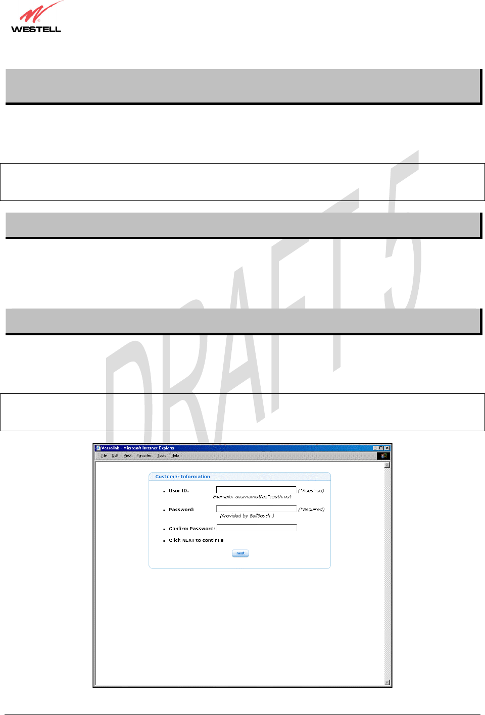
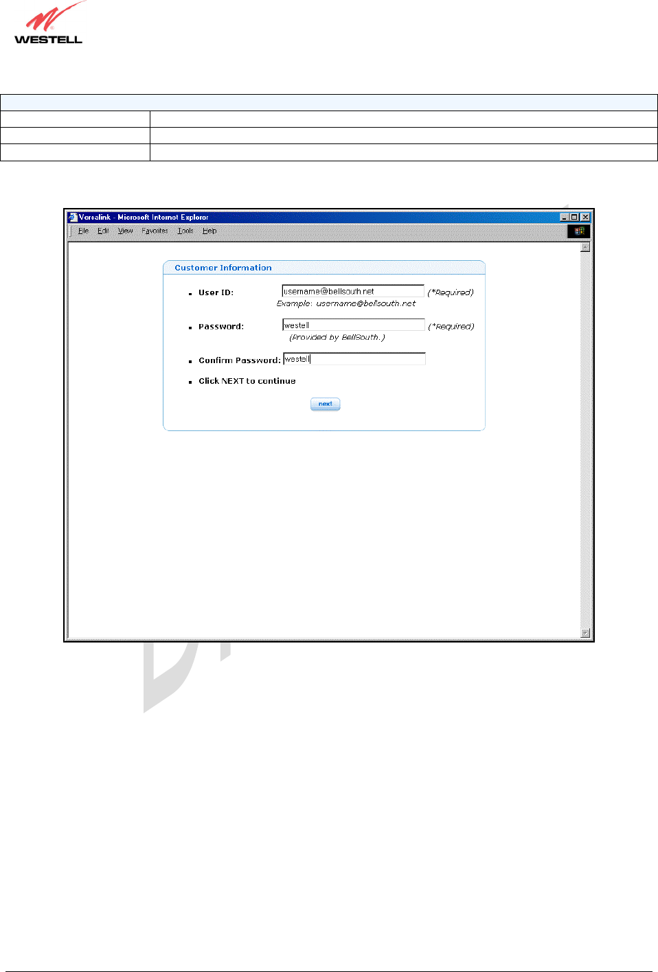
6.2 Setting Up Customer Information
After installing the VersaLink™ Gateway, bring up your Web browser and type http://launchmodem/ in your
browser’s address bar. Next, press ‘Enter’ on your keyboard. The following Customer Information page will be
displayed. This page allows you to enter the appropriate information needed for your BellSouth Internet connection.
NOTE: The Email Address, DSL Phone Number and Password are required information for your Internet
connection. You must enter this information in the fields provided to proceed with the installation. Contact the
BellSouth help desk at 1-888-321-2DSL (2375) if you need assistance with your customer information settings.
030-300452 Rev. A
BellSouthVersaLinkGateway
3/6/06 – Draft 5
030-300452 Rev. A 11 March 2006
VersaLink Gateway (Model 327W)
User Guide
Customer Information
User ID If applicable and different from your email address.
Password Provided by BellSouth.
Confirm Password Provided by BellSouth.
Enter the appropriate values in the Customer Information page, and then click next to continue.
030-300452 Rev. A
BellSouthVersaLinkGateway
3/6/06 – Draft 5
030-300452 Rev. A 12 March 2006
VersaLink Gateway (Model 327W)
User Guide
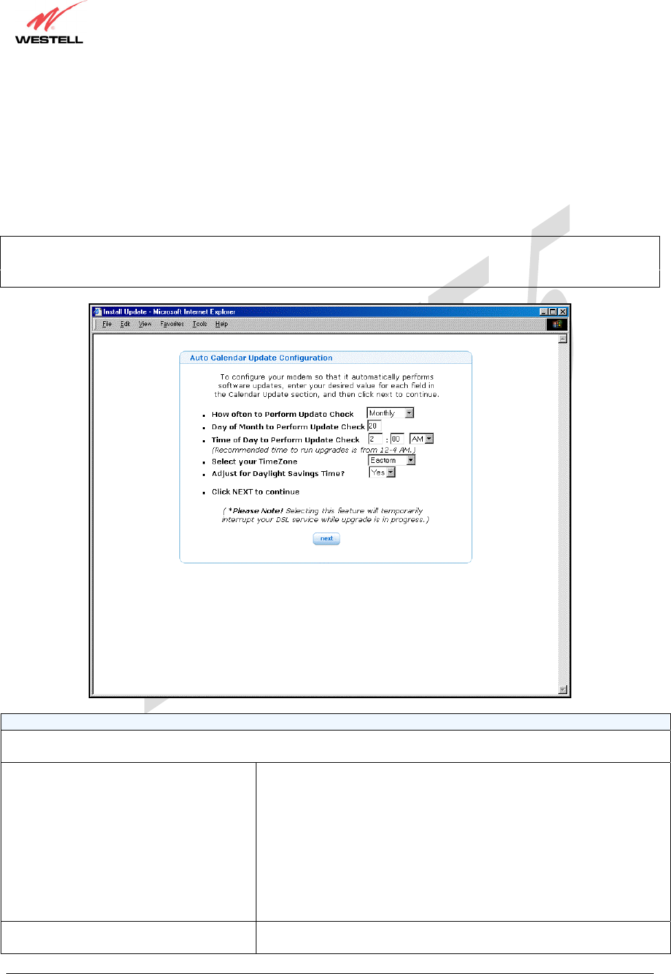
After you have entered the appropriate values in the Customer Information page and clicked next, the following
Auto Calendar Update Configuration page will be displayed. The Auto Calendar Update Configuration page
enables you to configure your modem to automatically perform software updates when updates are available for
your modem. If you change any settings in the modem web pages, you must click save to allow the settings to take
effect.
Enter your desired values in the Auto Calendar Update Configuration page, and then click save. Click Back to
return to the Home Summary page.
NOTE: You may also perform software updates via the Update Modem submenu at the Auto Calendar
Configuration page. This feature will temporarily interrupt your DSL service while a software upgrade is in
progress.
Auto Calendar Update Configuration
To configure your modem so that it automatically performs software updates, enter your desired value for each field in
the Calendar Update section, and then click next to continue.
How Often to Perform Update Check Factory Default = Monthly
The interval that you want the modem to automatically perform a
software update if an update is available for your modem.
Possible responses are:
Disable - If selected, the modem will not automatically perform a
software update because Calendar Update is turn off.
Bi-Weekly – If selected the software update will occur every two weeks
if an update is available for your modem.
Monthly – If selected the software update will occur once a month if an
update is available for your modem.
Day of Month to Perform Update Check Factory Default = Any value from 1 through 28
The Da
y
of Month that
y
ou want to the modem to
p
erform the u
p
date if
030-300452 Rev. A
BellSouthVersaLinkGateway
3/6/06 – Draft 5
030-300452 Rev. A 13 March 2006
VersaLink Gateway (Model 327W)
User Guide
an update is available for your modem.
Possible responses are:
1 through 28 (Note: If you enter a value lower than 1 or higher than 28,
an error message will appear when you click save.)
Time of Day to Perform Update Check Factory Default = 2:00 A.M.
You may choose your desired setting (A.M. or P.M.). However, the
recommended time to perform your software update is 12-4:00 A.M. due
to network traffic.
Select your Time Zone Factory Default = Eastern
The Time Zone of your area.
Possible responses are:
Greenwich, Atlantic, Eastern, Central, Mountain, Pacific
Adjust for Daylight Savings Time? Factory Default = Yes
If ‘No’ is selected, the update will not adjust for Daylight Savings Time.
6.3 Establishing Your PPP Session
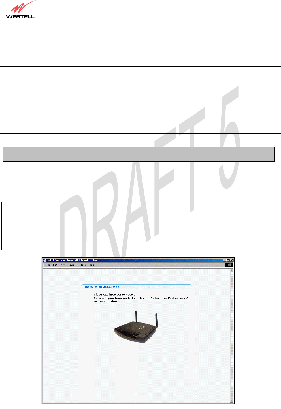
After you click save in the Auto Calendar Update Configuration page, the following Installation Completed
page will be displayed. Confirm that the modem’s Internet LED is solid green. If the Internet LED is solid green,
this indicates that you have established a PPP session with BellSouth and you may now browse the Internet. Close
all browser windows, and then re-open your browser to launch your Bellsouth® FastAccess® DSL connection.
NOTE: If your modem attempts to connect to the Internet and the connection fails, the Internet LED on the modem
will light red and then return to the off state. Check your hardware components to ensure that all cables are properly
connected (see section 5, Table 1. LED States and Descriptions, for details on the modem’s LEDs). Next, go to
section 16, Appendix A: Troubleshooting Connection Failures, to troubleshoot the problem and establish a
connection. If problems persist, contact the BellSouth help desk at 1-888-321-2DSL (2375) for further instructions.
Please do not proceed with the modem’s configuration until you have confirmed that the Internet LED is solid
green.
030-300452 Rev. A
BellSouthVersaLinkGateway
3/6/06 – Draft 5
030-300452 Rev. A 14 March 2006
VersaLink Gateway (Model 327W)
User Guide
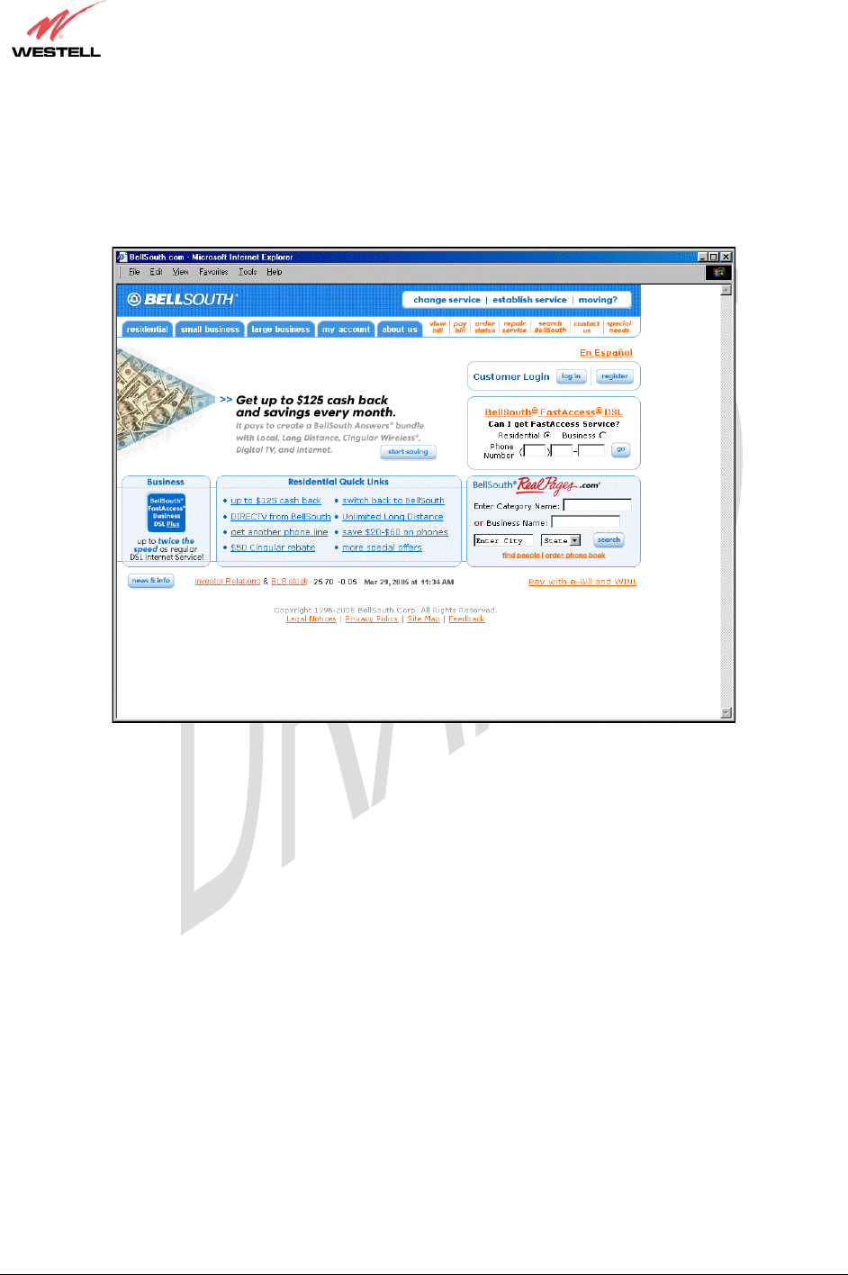
For example, after you have confirmed that the Internet LED on your modem is solid green, type
http://www.bellsouth.com in you browser’s address bar and press “Enter” on your keyboard. The BellSouth®
home page will be displayed. Please note that the actual web page might differ from the page displayed in this
document.
When you are ready to access the modem’s web pages, proceed to section 8 (Configuring VersaLink) for
instructions.
030-300452 Rev. A
BellSouthVersaLinkGateway
3/6/06 – Draft 5
030-300452 Rev. A 121 March 2006
VersaLink Gateway (Model 327W)
User Guide
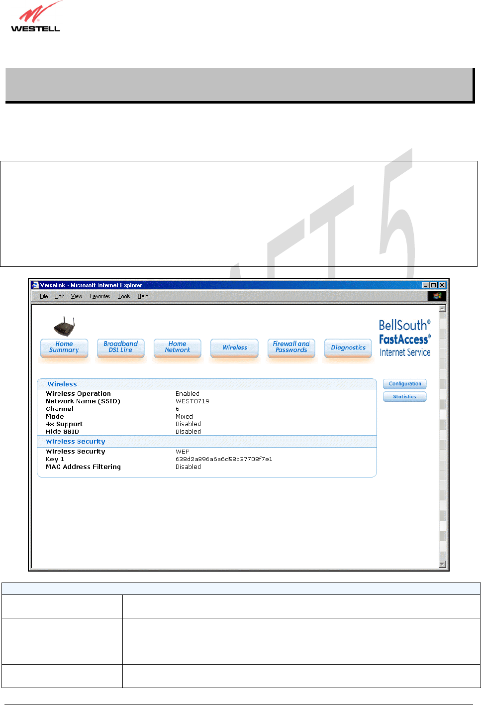
12. WIRELESS
If you click on Wireless at the main menu, the following page will be displayed. This page enables you to set up the
wireless network settings of your modem. To configure the wireless settings for VersaLink, click on the
Configuration button at the right of the page.
IMPORTANT: If you are connecting to the modem via a wireless network adapter, the service set ID (SSID) must
be the same for both the Westell modem and your PC’s wireless network adapter. The default Network Name
(SSID) for the modem is the serial number of the unit located below the bar code on the bottom of the unit and also
on the Westell shipping carton. (The SSID displayed in the following page is WEST0719; however, your SSID
might differ from the SSID displayed in this page.) To communicate with the modem, the PC’s wireless network
adapter must be configured with the SSID and pre-defined WEP Key 1 before you begin the modem’s Customer
Information setup and configuration procedures. Locate and run the utility software provided with your PC’s
Wireless network adapter and enter the SSID value. Later, for privacy, you should change the Network Name
(SSID) value in the Wireless page to your desired value.
Wireless
Wireless Operation Factory Default = Enable
Displays the current setting of the modem’s wireless operation.
Network Name (SSID) This string, (32 characters or less) is the name associated with the modem. To connect
to the modem, the SSID on a station card must match the SSID on the modem. (Note:
If the SSID on a modem is hidden, at the station card you must manually type the
SSID of the modem to which you are trying to connect.)
Channel Factory Default = 6
The modem transmits and receives data on this channel. Station cards do not have to
030-300452 Rev. A
BellSouthVersaLinkGateway
3/6/06 – Draft 5
030-300452 Rev. A 122 March 2006
VersaLink Gateway (Model 327W)
User Guide
be set to the same channel as the AP; the station cards scan all channels and look for
the modem with the correct SSID.
Mode Factory Default = Mixed
This setting allows station to communicate with the modem.
Possible responses:
Mixed: Station using 802.11b or 802.11g cards can communicate with the modem
using both 11b and 11g rates.
11b only: Stations using 802.11b or 802.11g cards can communicate with the modem
using only 11b rates.
11g only: Only stations using 802.11g cards can communicate with the modem.
4x Support Factory Default = Disable
If enabled, 4X support provides additional algorithms for increased throughput with
station cards that support 4x.
Hide SSID Factory Default = Disable
If Enabled, the modem will not broadcast the SSID. Stations must configure the SSID
to match the Network Name (SSID) in order to connect to the modem.
Wireless Security
Wireless Security Factory Default=WEP
Possible Responses:
Disabled: No security is used.
WPA-PSK: WPA encryption methods are used to encrypt and secure the connection
and the data being sent to and from the modem.
WEP: WEP encryption used to secure the data being sent to and from the modem;
when WEP is enabled, the risk of someone nearby accessing the modem is minimized.
Key n
(where n is 1 - 4 for WEP and is
blank for WPA-PSK)
Factory Default = Key 1
This information will only be displayed if Security is Enabled. This is the key that is
being used for the security mode selected above.
MAC Address Filtering Factory Default = Disable
If Enabled, only the stations in the MAC Filter Table can connect to the modem.
030-300452 Rev. A
BellSouthVersaLinkGateway
3/6/06 – Draft 5
030-300452 Rev. A 123 March 2006
VersaLink Gateway (Model 327W)
User Guide
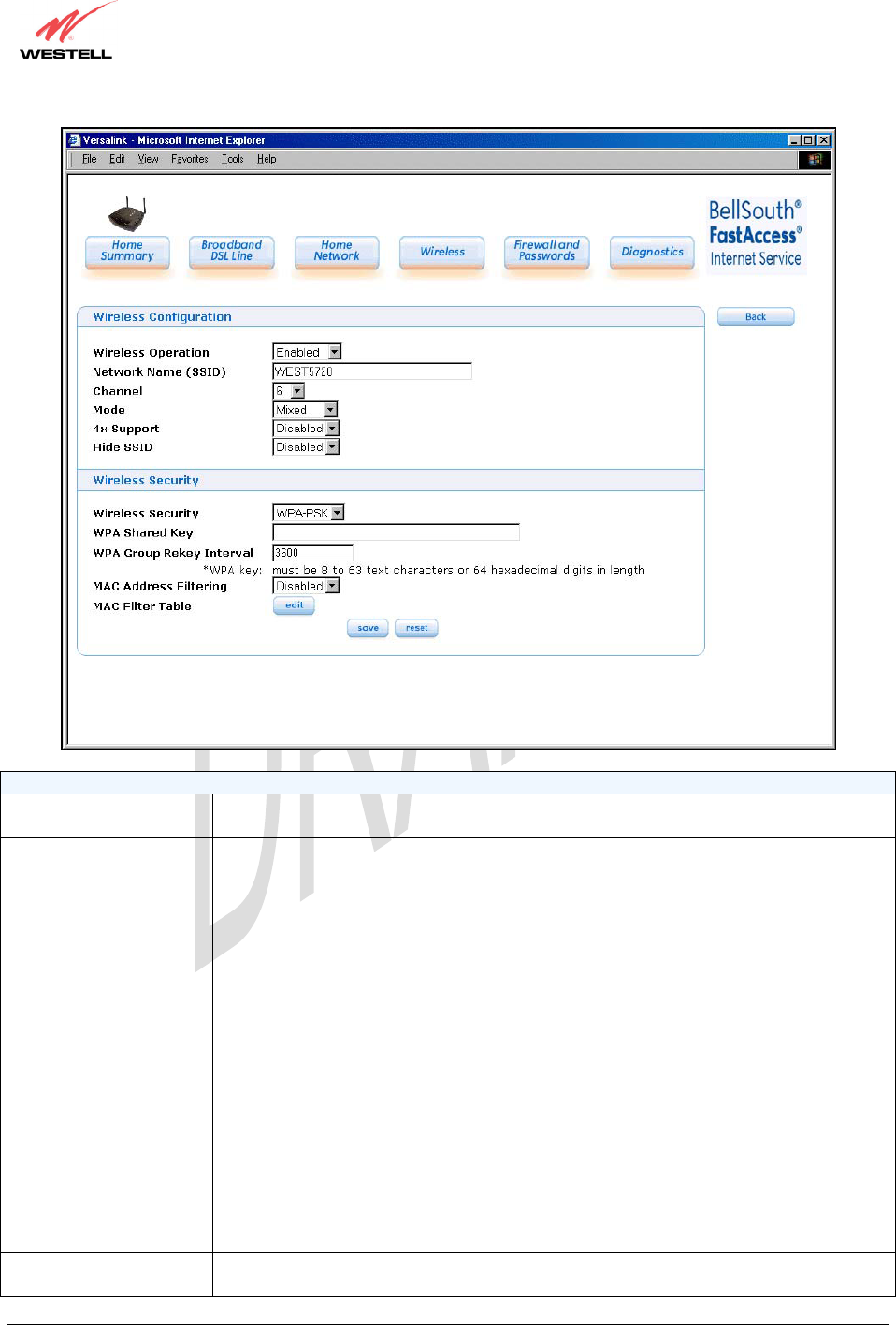
12.1 Configuration
If you click the Configuration button at the Wireless page, the following page will be displayed. Enter the desired
values in the fields provided, and then click save to allow the settings to take effect. To edit the MAC Filter Table,
click the edit button. To reset this page to the previously saved settings, click reset.
Wireless Configuration
Wireless Operation Factory Default = Enabled.
Displays the current setting of the modem’s wireless operation.
Network Name (SSID) This string, (32 characters or less) is the name associated with the modem. To connect
to the modem, the SSID on a station card must match the SSID on the modem. (Note: If
the SSID on a modem is hidden, at the station card you must manually type the SSID of
the modem to which you are trying to connect.)
Channel Factory Default = 6
The modem transmits and receives data on this channel. Station cards no dot have to be
set to the same channel as the modem; the station cards scan all channels and look for
the modem with the correct SSID.

030-300452 Rev. A
BellSouthVersaLinkGateway
3/6/06 – Draft 5
030-300452 Rev. A 124 March 2006
VersaLink Gateway (Model 327W)
User Guide
Mode Factory Default = Mixed
This setting allows station to communicate with the modem.
Possible responses are:
Mixed: Station using 802.11b or 802.11g cards can communicate with the modem using
both 11b and 11g rates.
11b only: Stations using 802.11b or 802.11g cards can communicate with the modem
using only 11b rates.
11g only: Only stations using 802.11g cards can communicate with the modem.
4x Support Factory Default = Disable
If enabled, 4X support provides additional algorithms for increased throughput with
station cards that support 4x.
Hide SSID Factory Default = Disable
If Enabled, the modem will not broadcast the SSID. Stations must configure the SSID to
match the Network Name (SSID) in order to connect to the modem.
Wireless Security (if WEP is used)
Wireless Security Factory Default=WEP
Possible Responses:
Disabled: No security is used.
WPA-PSK: WPA encryption methods are used to encrypt and secure the connection and
the data being sent to and from the modem.
WEP: WEP encryption used to secure the data being sent to and from the modem; when
WEP is enabled, the risk of someone nearby accessing the modem is minimized.
Authentication Type Factory Default = Open System
Possible responses:
Open System: Open System authentication is the default selection. WEP encryption is
not used for association.
Shared Key: WEP encryption is used for the association process and only stations
having the correct key can connect to the modem.
Key Select Factory Default = 1
Select Key 1 to Key 4 as the WEP key to be used. The key position must be the same in
both the modem and the station.
Key n
(where n is 1 - 4 for WEP and
is blank for WPA-PSK)
The WEP key is treated as either text or hexadecimal (hex) characters. The number of
characters is based on the key size selected. The key size 64 bit is either 5 text or 10 hex
characters, 128 bit is either 13 text or 26 hex characters, and 256 bit is either 29 text or
58 hex characters. Hexadecimal characters are 0-9 and A-F (or a-f). This key must be
the same in both the modem and the station. Some station cards use a “Pass Phrase.”
This is not the same as “text” and should not be used.
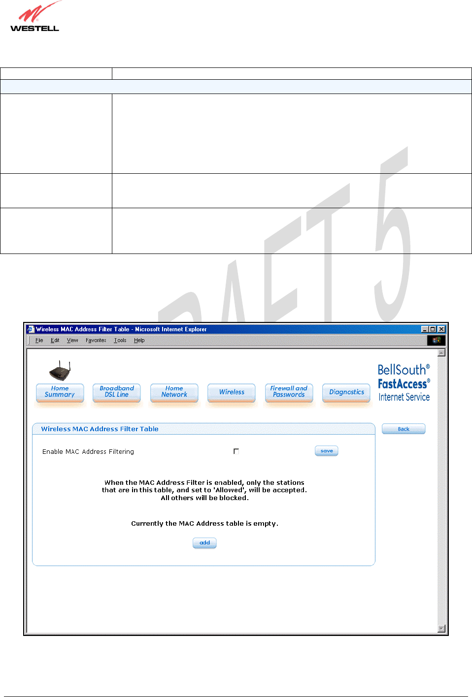
MAC Address Filtering Factory Default = Disabled
If Enabled, only the stations in the MAC Filter table can connect to the modem.
MAC Filter Table This table enables you to add, edit or delete MAC addresses of stations that are allowed
to communicate with the modem.
030-300452 Rev. A
BellSouthVersaLinkGateway
3/6/06 – Draft 5
030-300452 Rev. A 125 March 2006
VersaLink Gateway (Model 327W)
User Guide
Wireless Configuration
Wireless Operation Factory Default = Enabled.
Displays the current setting of the modem’s wireless operation.
Network Name (SSID) This string, (32 characters or less) is the name associated with the modem. To connect
to the modem, the SSID on a station card must match the SSID on the modem. (Note: If
the SSID on a modem is hidden, at the station card you must manually type the SSID of
the modem to which you are trying to connect.)
Channel Factory Default = 6
The modem transmits and receives data on this channel. Station cards no dot have to be
set to the same channel as the modem; the station cards scan all channels and look for
the modem with the correct SSID.
Mode Factory Default = Mixed
This setting allows station to communicate with the modem.
Possible responses are:
Mixed: Station using 802.11b or 802.11g cards can communicate with the modem using
both 11b and 11g rates.
11b only: Stations using 802.11b or 802.11g cards can communicate with the modem
using only 11b rates.
11g only: Only stations using 802.11g cards can communicate with the modem.
4x Support Factory Default = Disable
If enabled, 4X support provides additional algorithms for increased throughput with
station cards that support 4x.
Hide SSID Factory Default = Disable
If Enabled, the modem will not broadcast the SSID. Stations must confi
g
ure the SSID to
030-300452 Rev. A
BellSouthVersaLinkGateway
3/6/06 – Draft 5
030-300452 Rev. A 126 March 2006
VersaLink Gateway (Model 327W)
User Guide
match the Network Name (SSID) in order to connect to the modem.
Wireless Security (if WPA-PSK is used)
Wireless Security Factory Default=WEP
Possible Responses:
Disabled: No security is used.
WPA-PSK: WPA encryption methods are used to encrypt and secure the connection and
the data being sent to and from the modem.
WEP: WEP encryption used to secure the data being sent to and from the modem; when
WEP is enabled, the risk of someone nearby accessing the modem is minimized.
WPA Shared Key This string (8 to 63 characters of 64 hex characters) is the key used for encrypting
packets being sent to and from the modem. This key must be the same in both the
modem and the station.
WPA Group Rekey
Interval
Factory Default = 3600
The number of seconds between rekeying the WPA group key. A value of 0 means that
rekeying is disabled. The Shared Key is the initial key and new keys are created and
used, based on that key, at each Rekey Interval.
If you clicked edit, the following page will be displayed. Click the add button to add stations to the MAC Address
table, and then click save to save the settings. To add more entries, click the add button. When you have finished
adding entries, click the box adjacent Enable MAC Address Filtering (a check mark will appear in the box). Next,
click save to save the settings.
030-300452 Rev. A
BellSouthVersaLinkGateway
3/6/06 – Draft 5
030-300452 Rev. A 127 March 2006
VersaLink Gateway (Model 327W)
User Guide
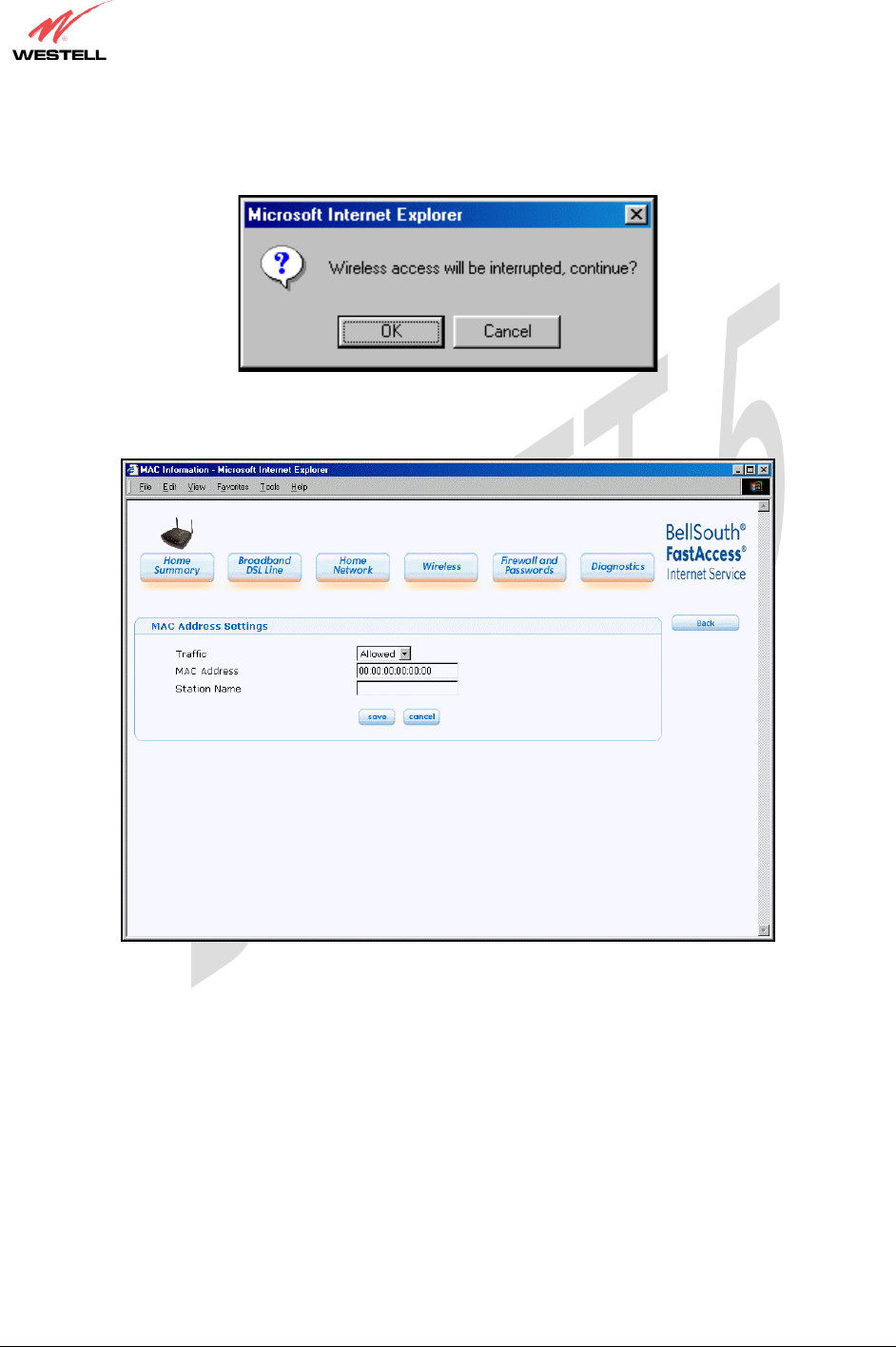
If you clicked save in the Wireless Configuration page, the following pop-up will be displayed. Click OK to
continue.
If you clicked the add button in the Wireless MAC Address Filter Table, the following page will be displayed.
After you have entered the desired MAC Address settings, click save to save your settings.
030-300452 Rev. A
BellSouthVersaLinkGateway
3/6/06 – Draft 5
030-300452 Rev. A 128 March 2006
VersaLink Gateway (Model 327W)
User Guide
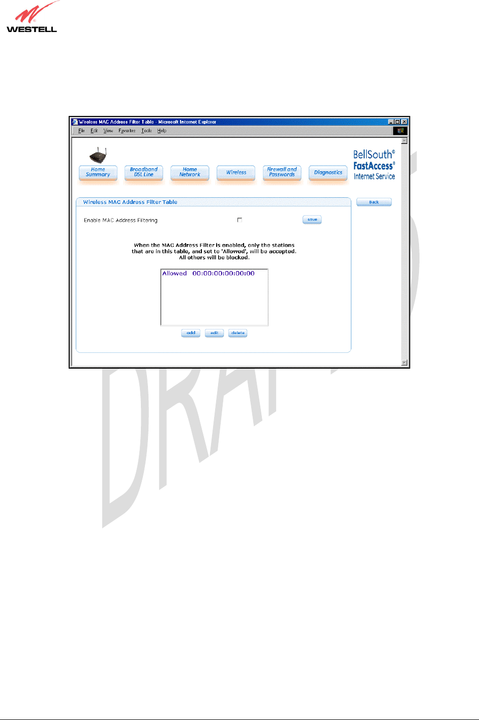
If you clicked save, the following page will be displayed. This page enables you to add, edit or delete stations at the
MAC Address Filter table. After you have made the desired changes to this page, click the save button to allow the
changes to take effect.
030-300452 Rev. A
BellSouthVersaLinkGateway
3/6/06 – Draft 5
030-300452 Rev. A 129 March 2006
VersaLink Gateway (Model 327W)
User Guide
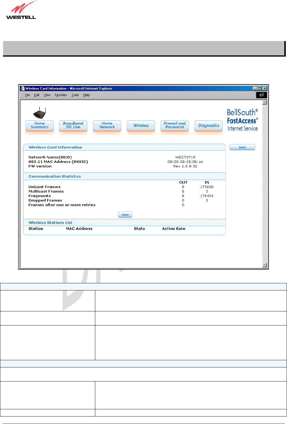
12.2 Statistics
If you click the Statistics button at the Wireless page, the following page will be displayed. This page provides
information about your modem’s wireless connection. To clear the statistics in this page, click on clear.
Wireless Card Information
Network Name (SSID) This string, (32 characters or less) is the name associated with the Access
Point (AP). To connect to the AP, the Service Set ID (SSID) on a Station
card must match the SSID on the AP.
802.11 MAC Address (BSSID) This is the Media Access Controller address of the AP. It is used as the Basic
Service Set Identifier (BSSID).
FW Version This is the Network Interface Card Identifier. It uniquely identifies the
hardware platform of the AP. This is used with other information to
determine if the inserted card can be used as an AP, and if so, the version of
AP firmware to be used. Not all makes of wireless station cards can be used
as an AP.
Communication Statistics
NOTE: Data preceded by OUT pertain to transmissions from the VersaLink to a station; VersaLink is the source.
Data preceded by IN pertain to data received by VersaLink; VersaLink is the destination.
OUT-Unicast Frames The number of successfully transmitted frames whose destination address
was a single station; not necessarily the same station, but to any single
station as opposed to a transmission that multiple stations would receive-as
in the case of broadcast message.
OUT-Multicast Frames The number of successfull
y
transmitted frames whose destination a
d
dress
030-300452 Rev. A
BellSouthVersaLinkGateway
3/6/06 – Draft 5
030-300452 Rev. A 130 March 2006
VersaLink Gateway (Model 327W)
User Guide
was a multicast address (received by more that one station): not necessarily
broadcast to all stations, but more than a single station. Broadcast messages
are included in the count.
OUT-Fragments The number of successful transmissions made. This will typically be greater
than the sum of the Unicast and Multicast frames because large frames are
broken into multiple transmissions. The number of fragments per frame is
based on the Fragmentation Threshold setting (not user-configurable).
OUT-Dropped Frames, too many
retries
The number of frames that did not transmit due to the short or long retry
limit being reached because no acknowledgement or CTS was received.
OUT-Frames after one or more
retries
The number of frames that successfully transmitted after more than one
retry. Any fragment of a frame that required multiple retries would
increment this counter for the whole frame.
IN-Unicast Frames The number of successfully received frames whose destination address was a
single location, not necessarily the same location, but to any single location
as opposed to the broadcast address.
IN-Multicast Frames The number of successfully received frames whose destination address was a
multicast address. Broadcast messages are included in this count.
IN-Fragments The number of fragments successfully received. This may not be equal to the
sum of the Unicast and Multicast frames because large frames are broken
into multiple transmissions. The number of fragments per frame is based on
the Fragmentation Threshold setting (not user-configurable) on the source
station.
IN-Dropped Frames The number of frames that were not received by VersaLink due to the short
or long retry limit being reached because no acknowledgement or CTS was
received.
Wireless Stations List
Station This number indicates the order in which the stations are first accessed by
VersaLink.
MAC Address The Media Access Controller Address assigned to the station.
State The current state of the negotiation between the station and VersaLink.
Active Rate The current transmit and receive rate.

030-300452 Rev. A
BellSouthVersaLinkGateway
3/6/06 – Draft 5
030-300452 Rev. A 170 March 2006
VersaLink Gateway (Model 327W)
User Guide
18. PRODUCT SPECIFICATIONS
DSL
x DSL Line Code: Discrete Multi-Tone (DMT)
x DSL Rates: 32 kbps to 8 Mbps downstream
and 32 kbps to 800 Kbps upstream
x Power spectral density: -40 dBm/Hz
x DSL Impedance: 100 Ohms
x DSL Performance: Performance: per
G.992.1, ANSI T1.413.
Protocol Features
x Bridge Encapsulation per RFC2684
(Formerly RFC1483)
x Logical Link Control/ Subnetwork Access
Protocol (LLC/SNAP)
x Software Upgradeable
x PPPoE Support
x ATM SAR: Internal to Modem
System Requirements for 10/100 Base-T/Ethernet
x Pentium Class PC or above, Macintosh
x Microsoft Windows (98 SE, 2000, ME, NT
4.0, or XP), Linux, or MAC OS X installed
x Operating system CD
x Internet Explorer 4.x or Netscape Navigator
4.x or higher
x 64 MB RAM (128 MB recommended)
x Ethernet 10/100 Base-T interface
x 10 MB of free hard drive space
x TCP/IP Protocol Stack installed
x 10/100 Base-T Network Interface Card (NIC)
System Requirements for Wireless
x Pentium® or equivalent and above class
machines
x Microsoft® Windows® (98 ME, 2000, or
XP) or Macintosh® OS X installed
x Operating System CD on hand
x Internet Explorer 4.x or Netscape Navigator
4.x or higher
x 64 MB RAM (128 MB recommended)
x 10 MB of free hard drive space
x IEEE 802.11b/g/g+ PC adapter
LEDs
x Power
x E1, E2, E3, E4
x Wireless
x DSL
x Internet
Connectors
x DSL/LINE: 6-pin modular jack RJ-11
x Ethernet: 8-pin RJ-45 modular jack
x Power connector: 12V DC
x Wireless IEEE 802.11b/g SMA connector
and antenna
Environmental
x Ambient Operating Temperature: +32 to
+104°F (0 to +40°C)
x Relative Humidity: 5 to 95%, non-
condensing
Power Supply/Consumption
x 120 VAC to 12V DC wall-mount power
supply
x Less than 4 watts typical, from 120 VAC
Environmental
x Ambient Operating Temperature: +32 to
+104°F (0 to +40°C)
x Relative Humidity: 5 to 95%, non-
condensing
EMC/Safety/Regulatory Certifications
x EMC: FCC Part 15, Class B
x UL Standard 60950, 3rd Edition
x CAN/CSA Standard C22.2 No. 60950
x UL
x CSA
x ACTA 968-A
x Industry Canada CS03

030-300452 Rev. A
BellSouthVersaLinkGateway
3/6/06 – Draft 5
030-300452 Rev. A 171 March 2006
VersaLink Gateway (Model 327W)
User Guide
19. SOFTWARE LICENSE AGREEMENT
READ THE TERMS AND CONDITIONS OF THIS LICENSE AGREEMENT CAREFULLY. THIS
SOFTWARE IS COPYRIGHTED AND LICENSED (NOT SOLD). BY INSTALLING AND OPERATING
THIS PRODUCT, YOU ARE ACCEPTING AND AGREEING TO THE TERMS OF THIS LICENSE
AGREEMENT. IF YOU ARE NOT WILLING TO BE BOUND BY THE TERMS OF THIS LICENSE
AGREEMENT, YOU SHOULD PROMPTLY RETURN THE SOFTWARE AND HARDWARE TO
WESTELL TECHNOLOGIES, INC. THIS LICENSE AGREEMENT REPRESENTS THE ENTIRE
AGREEMENT CONCERNING THE SOFTWARE BETWEEN YOU AND WESTELL TECHNOLOGIES,
INC. (REFERRED TO AS "LICENSOR"), AND IT SUPERSEDES ANY PRIOR PROPOSAL,
REPRESENTATION, OR UNDERSTANDING BETWEEN THE PARTIES.
1. License Grant. Licensor hereby grants to you, and you accept, a nonexclusive license to use the
SOFTWARE Compact Disk (CD) and the computer programs contained therein in machine-readable, object
code form only (collectively referred to as the "SOFTWARE"), and the accompanying User Documentation,
only as authorized in this License Agreement. The SOFTWARE may be used only in connection with the
number of systems for which you have paid license fees as dictated in your support agreement. You agree
that you will not assign, sublicense, transfer, pledge, lease, rent, or share your rights under this License
Agreement. You agree that you may not nor allow others to reverse assemble, reverse compile, or otherwise
translate the SOFTWARE.
You may retain the SOFTWARE CD for backup purposes only. In addition, you may make one copy of the
SOFTWARE in any storage medium for backup purposes only. You may make one copy of the User's
Manual for backup purposes only. Any such copies of the SOFTWARE or the User's Manual shall include
Licensor's copyright and other proprietary notices. Except as authorized under this paragraph, no copies of
the SOFTWARE CD or any portions thereof may be made by you or any person under your authority or
control.
2. Licensor's Rights. You acknowledge and agree that the SOFTWARE and the User's Manual are
proprietary products of Licensor protected under U.S. copyright law. You further acknowledge and agree
that all right, title, and interest in and to the SOFTWARE, including associated intellectual property
rights, are and shall remain with Licensor. This License Agreement does not convey to you an interest in or to
the SOFTWARE, but only a limited right of use revocable in accordance with the
terms of this License Agreement.
3. License Fees. The fees paid by you under the support agreement are paid in consideration of the licenses
granted under this License Agreement.
4. Term. This License Agreement is effective upon your opening of this package and shall continue until
terminated. You may terminate this License Agreement at any time by returning the SOFTWARE CD and
all copies thereof and extracts there from to Licensor. Licensor may terminate this License Agreement upon
the breach by you of any term hereof. Upon such termination by Licensor, you agree to return to Licensor
the SOFTWARE CD and all copies and portions thereof.
5. Limited Warranty. Licensor warrants, for your benefit alone, for a period of 90 days from the date of
commencement of this License Agreement (referred to as the "Warranty Period") that the SOFTWARE CD
in which the SOFTWARE is contained are free from defects in material and workmanship. Licensor further
warrants, for your benefit alone, that during the Warranty Period the SOFTWARE shall operate
substantially in accordance with the functional specifications in the User's Manual. If during the Warranty
Period, a defect in the SOFTWARE CD appears, you may return the SOFTWARE CD to Licensor for
replacement. You agree that the foregoing constitutes your sole and exclusive remedy for breach by Licensor
of any warranties made under this Agreement.

030-300452 Rev. A
BellSouthVersaLinkGateway
3/6/06 – Draft 5
030-300452 Rev. A 172 March 2006
VersaLink Gateway (Model 327W)
User Guide
EXCEPT FOR THE WARRANTIES SET FORTH ABOVE, THE SOFTWARE CD,
AND THE SOFTWARE CONTAINED THEREIN, ARE LICENSED "AS IS," AND
LICENSOR DISCLAIMS ANY AND ALL OTHER WARRANTIES, WHETHER EXPRESS
OR IMPLIED, INCLUDING, WITHOUT LIMITATION, ANY IMPLIED WARRANTIES
OF MERCHANTABILITY OR FITNESS FOR A PARTICULAR PURPOSE.
6. Limitation of Liability. Licensor's cumulative liability to you or any other party for any loss or damages
resulting from any claims, demands, or actions arising out of or relating to this Agreement shall not exceed
the license fee paid to Licensor for the use of the SOFTWARE. In no event shall Licensor be liable for any
indirect, incidental, consequential, special, or exemplary damages or lost profits, even if Licensor has been
advised of the possibility of such damages. SOME STATES DO NOT ALLOW THE LIMITATION OR
EXCLUSION OF LIABILITY FOR INCIDENTAL OR CONSEQUENTIAL DAMAGES, SO THE ABOVE
LIMITATION OR EXCLUSION MAY NOT APPLY TO YOU.
7. Governing Law. This License Agreement shall be construed and governed in accordance with the laws of
the State of Illinois. You submit to the jurisdiction of the state and federal courts of the state of Illinois and
agree that venue is proper in those courts with regard to any litigation arising under this Agreement.
8. Costs of Litigation. If any action is brought by either party to this License Agreement against the other
party regarding the subject matter hereof, the prevailing party shall be entitled to recover, in addition to any
other relief granted, reasonable attorney fees and expenses of litigation.
9. Severability. Should any term of this License Agreement be declared void or unenforceable by any court of
competent jurisdiction, such declaration shall have no effect on the remaining terms hereof.
10. No Waiver. The failure of either party to enforce any rights granted hereunder or to take action against
the other party in the event of any breach hereunder shall not be deemed a waiver by that party as to
subsequent enforcement of rights or subsequent actions in the event of future breaches.

030-300452 Rev. A
BellSouthVersaLinkGateway
3/6/06 – Draft 5
030-300452 Rev. A 173 March 2006
VersaLink Gateway (Model 327W)
User Guide
20. PUBLICATION INFORMATION
Westell® Versa Link™ Gateway (Model 327W)
User Guide Part no. 030-300452 Rev. A
Copyright © 2005 Westell, Inc.
All rights reserved.
Westell, Inc.
750 North Commons Drive
Aurora, Illinois 60504 USA
www.westell.com
All trademarks and registered trademarks are the property of their respective owners.
Filename:
BellSouthVersaLinkGateway_DRAFT4_toAlEngelkens.do
c
Directory: C:\CPE Files\327W30 BellSouth C99_VersaGwy for
Darko\UserGuide
Template: C:\Documents and Settings\salle\Application
Data\Microsoft\Templates\Normal.dot
Title:
Subject:
Author: Westell
Keywords:
Comments:
Creation Date: 2/16/2006 12:03 PM
Change Number: 6
Last Saved On: 3/6/2006 10:47 AM
Last Saved By: salle
Total Editing Time: 8 Minutes
Last Printed On: 3/6/2006 10:47 AM
As of Last Complete Printing
Number of Pages: 176
Number of Words: 24,138 (approx.)
Number of Characters: 137,592 (approx.)