Westell DSP85-CPG Digital Repeater User Manual NVRDSP85 L7U7C UserMan rJ3
Westell, Inc. Digital Repeater NVRDSP85 L7U7C UserMan rJ3
UserManual.wiki
>
Westell
>
DSP85 CPG User Manual
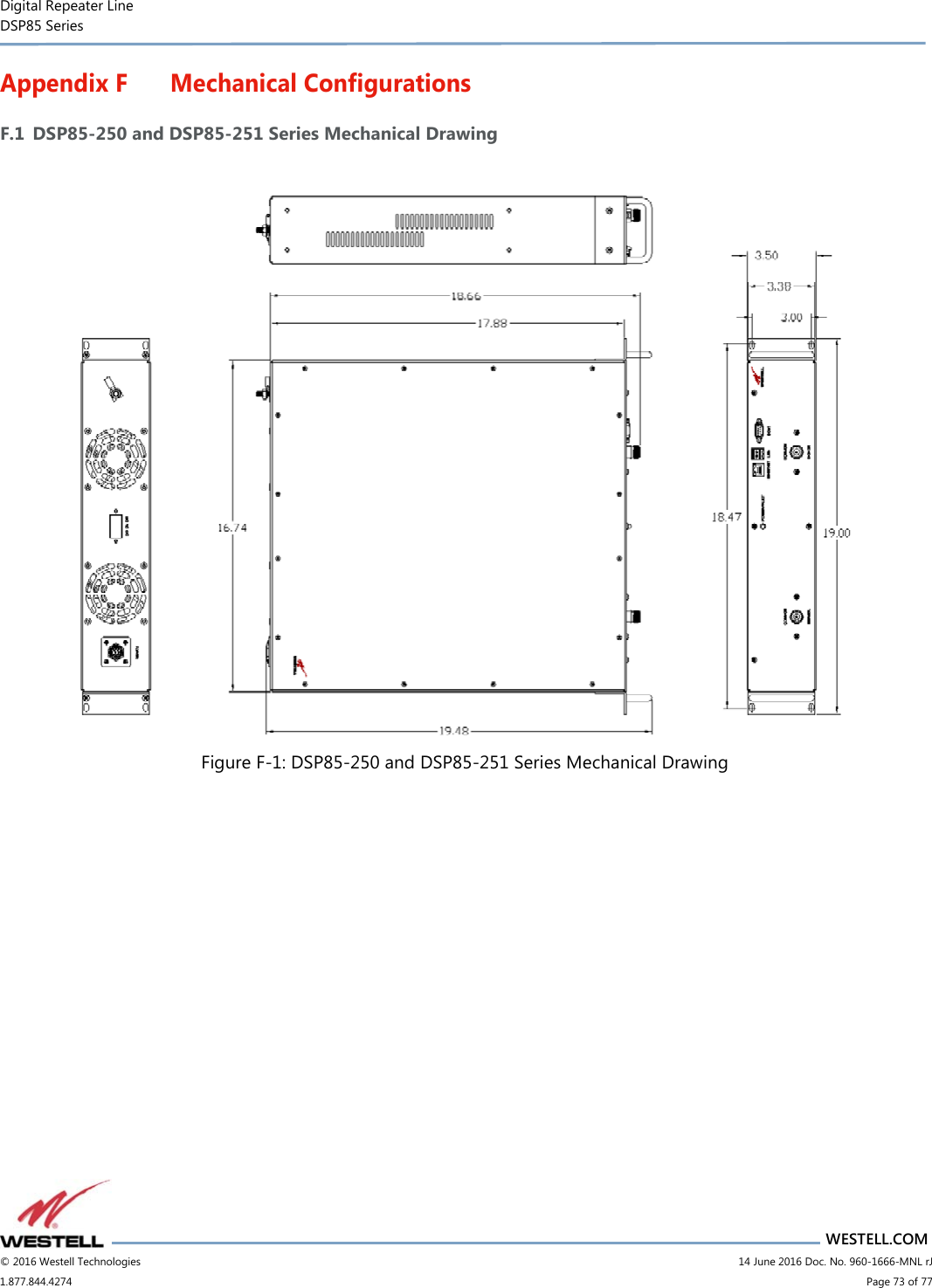
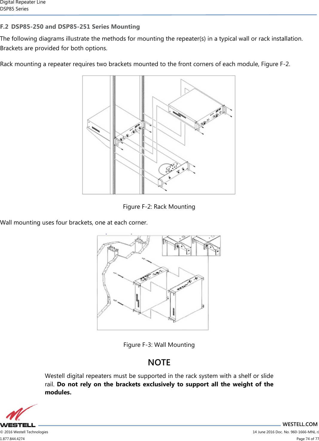
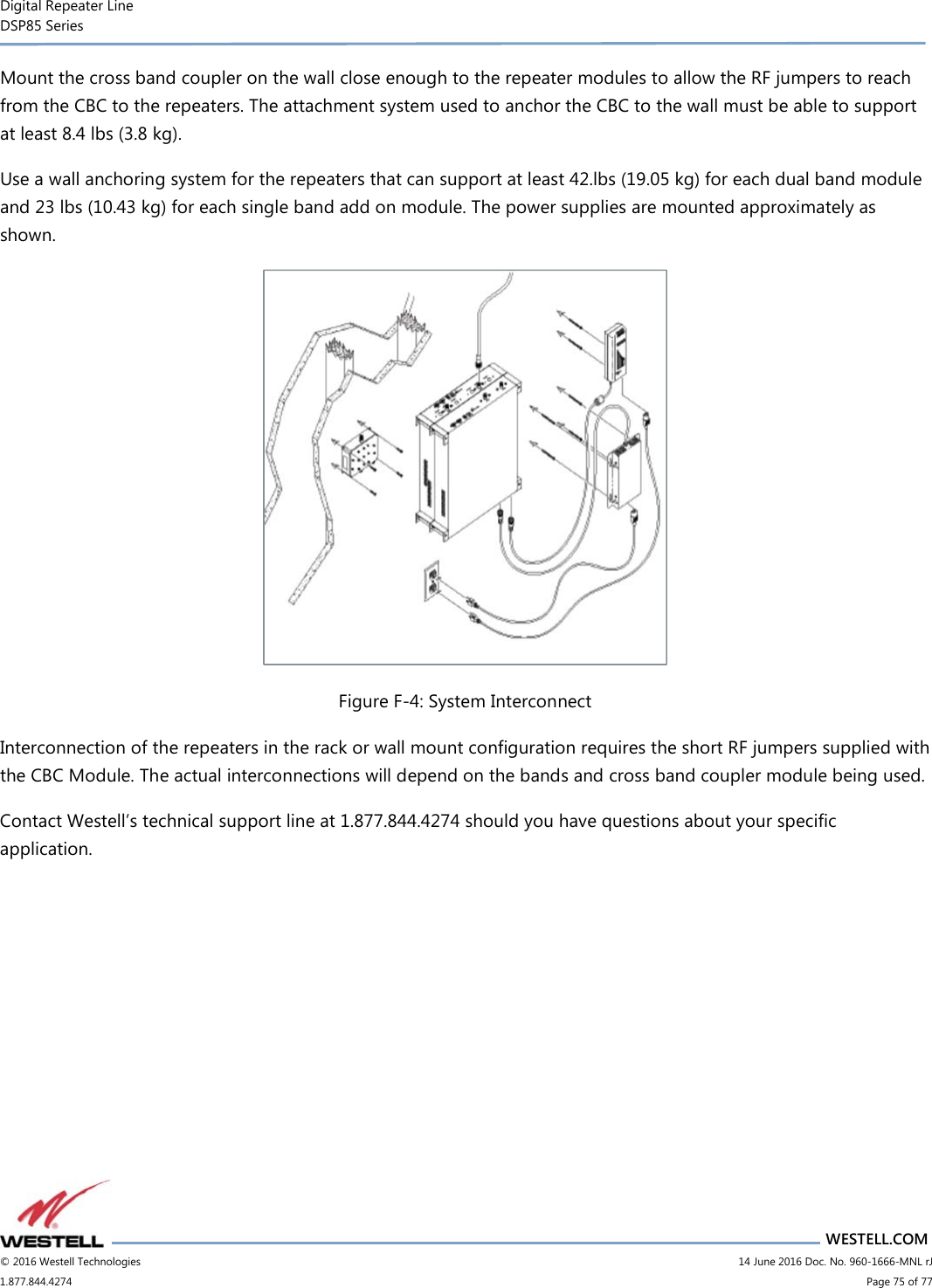
User Manual
Navigation menu
Upload a User Manual
Namespaces
Wiki Guide
HTML
PDF
Info
Views
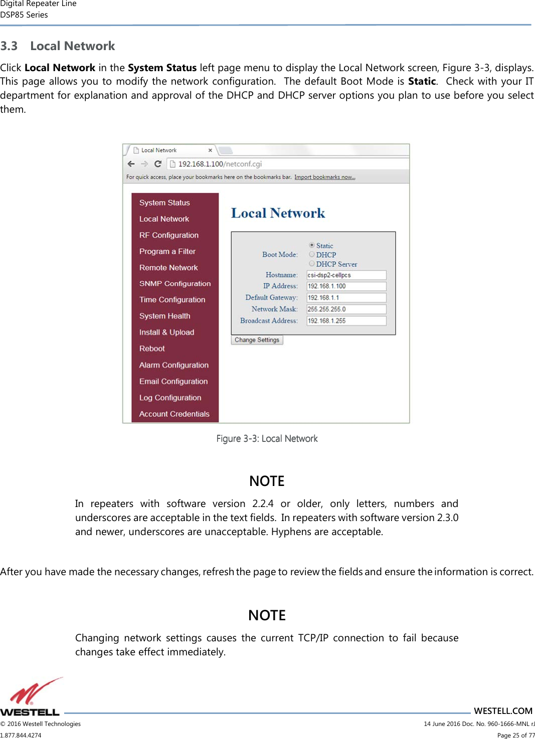
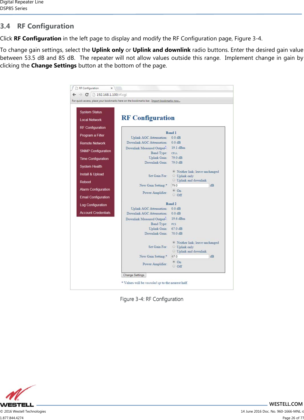
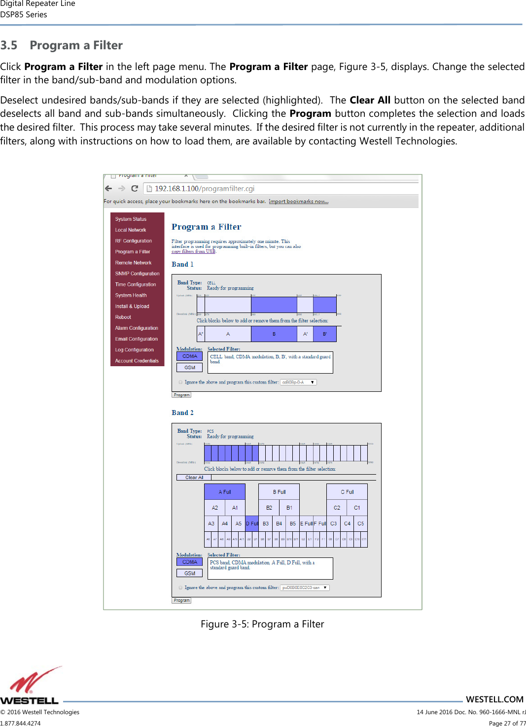
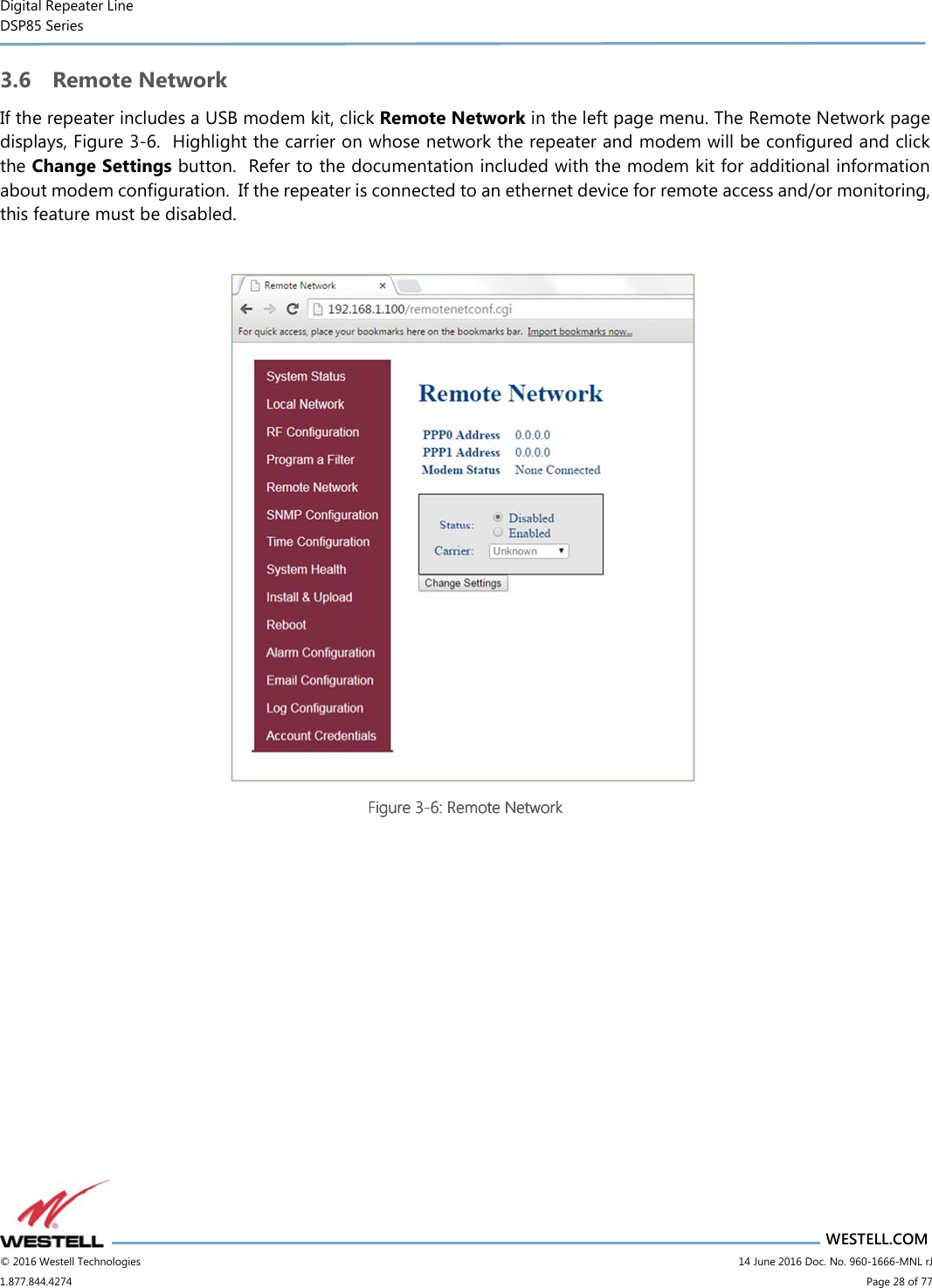
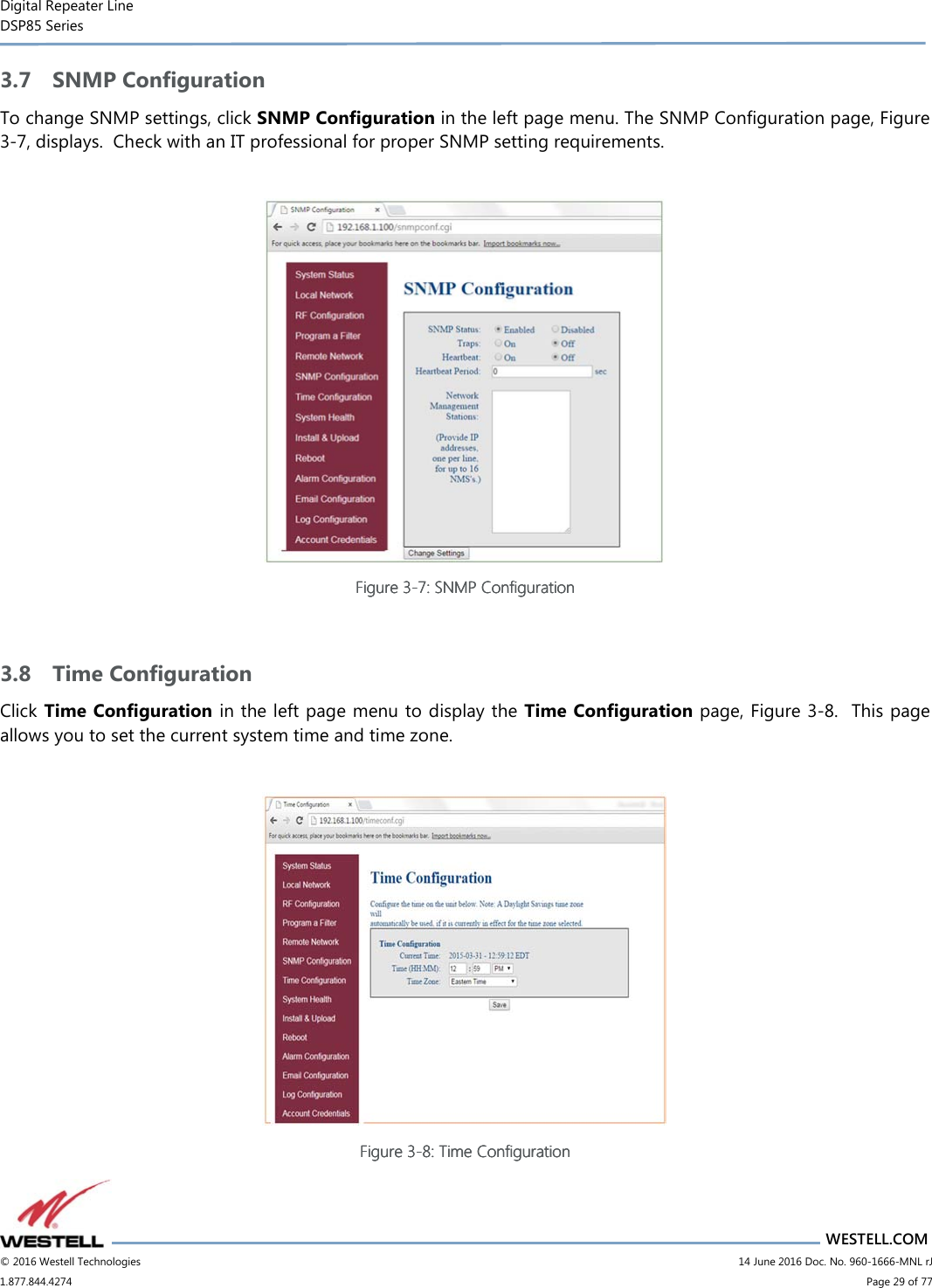
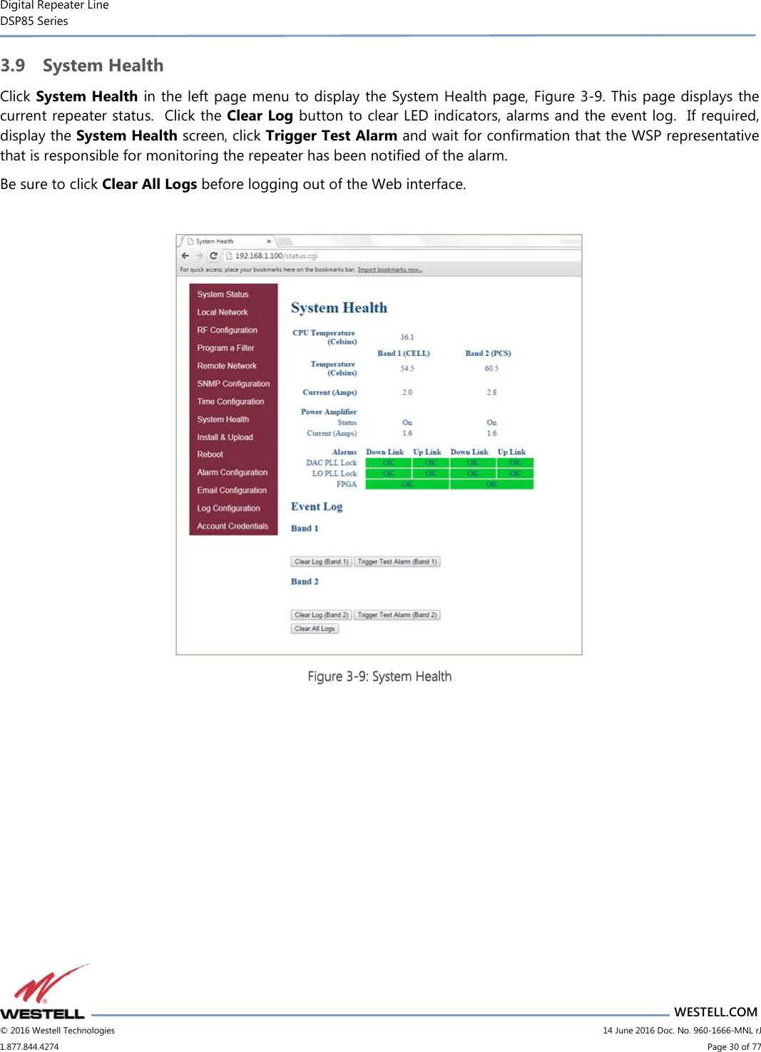
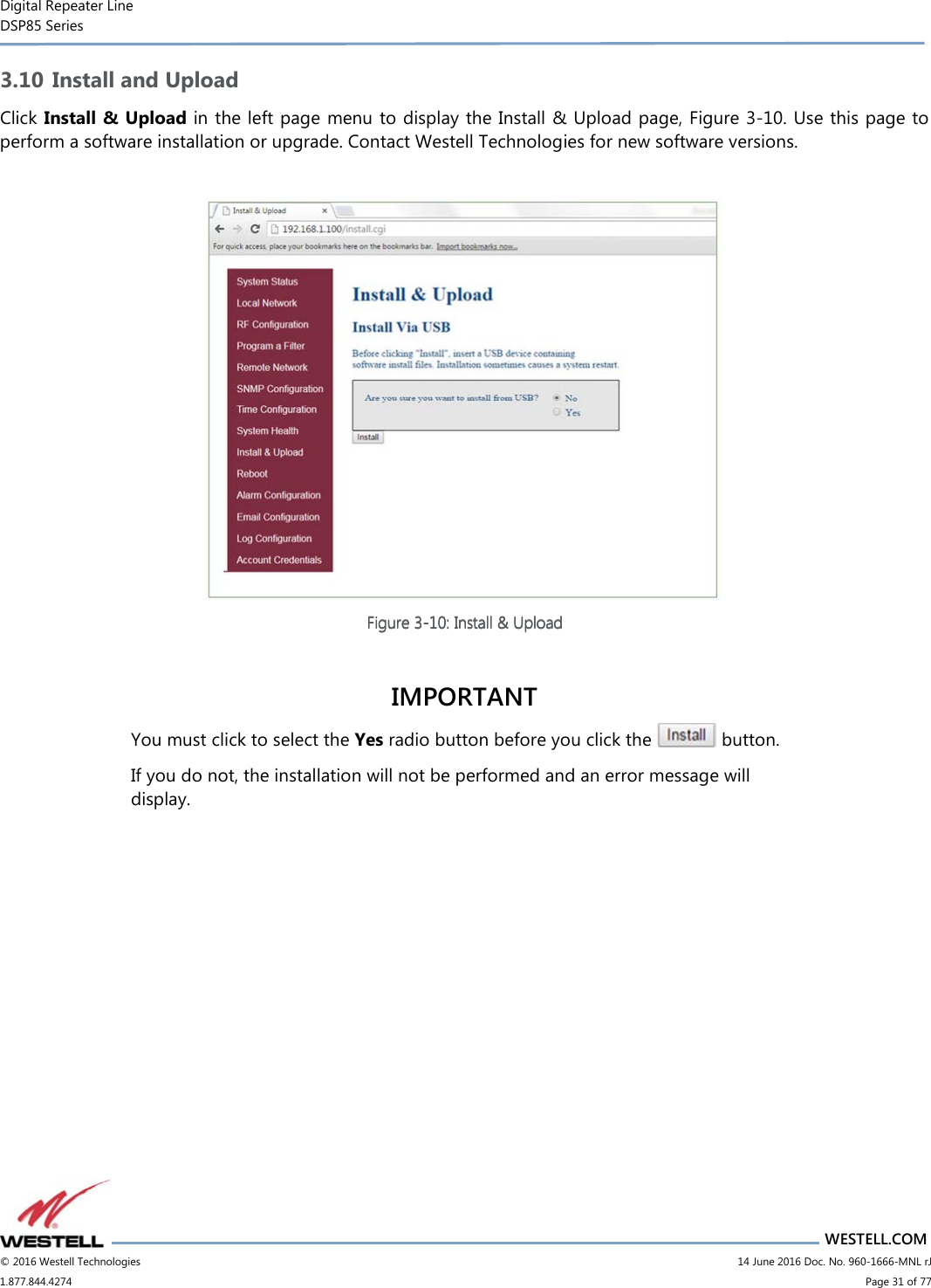
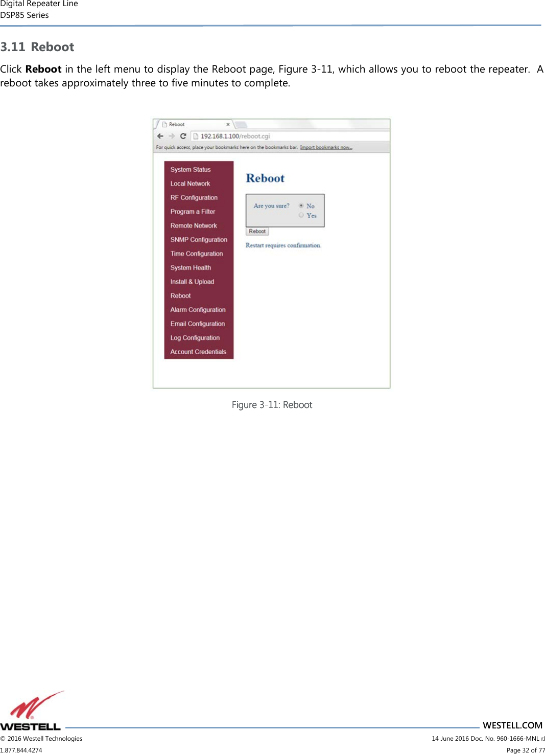
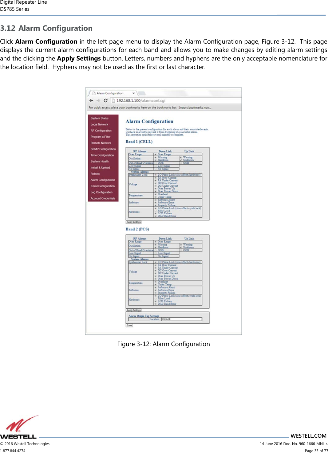
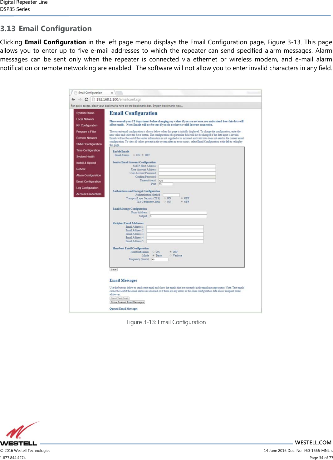
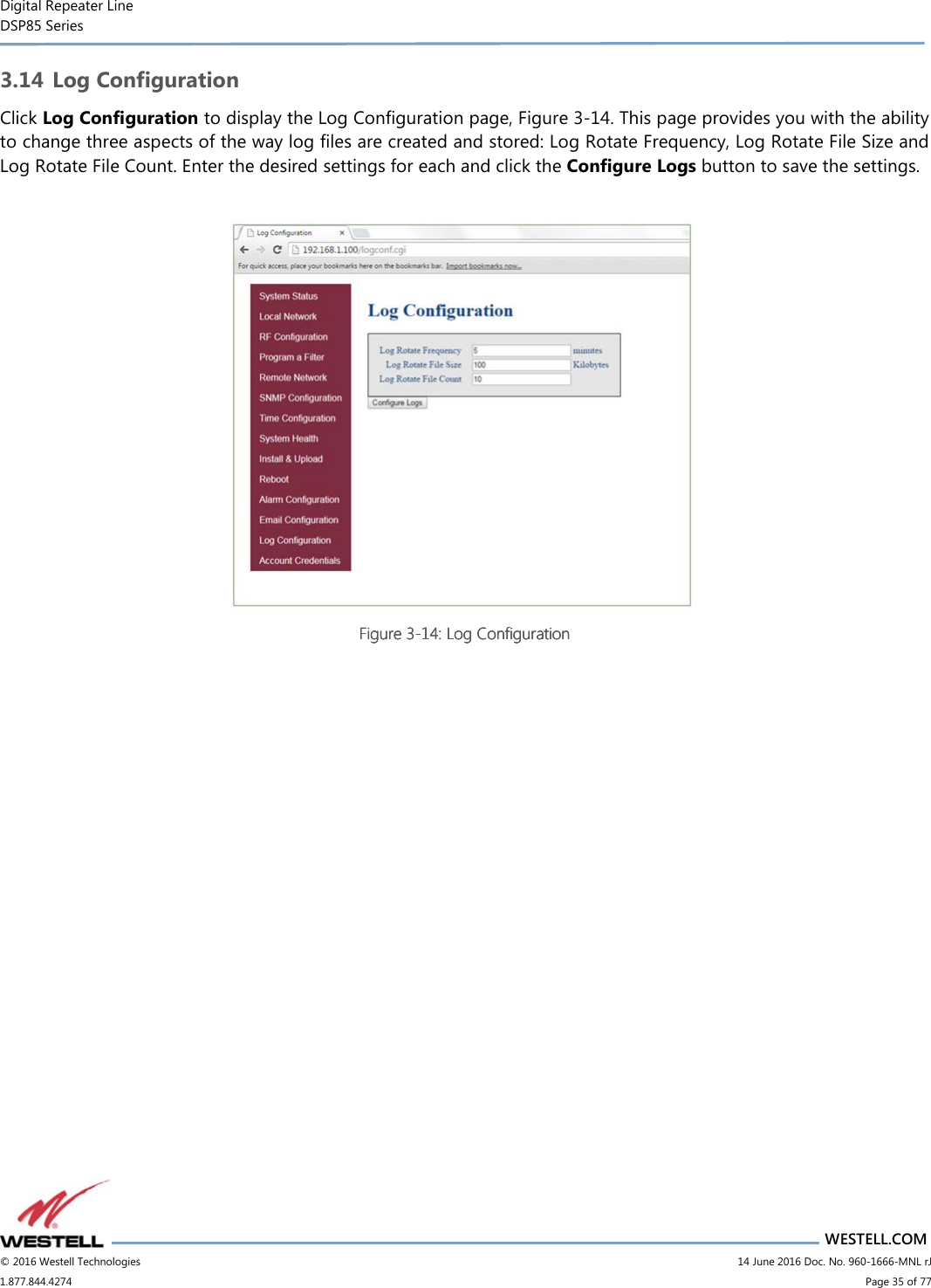
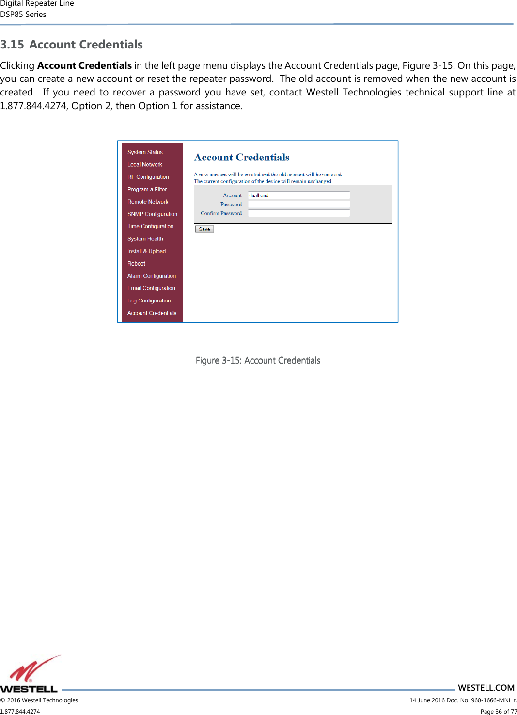
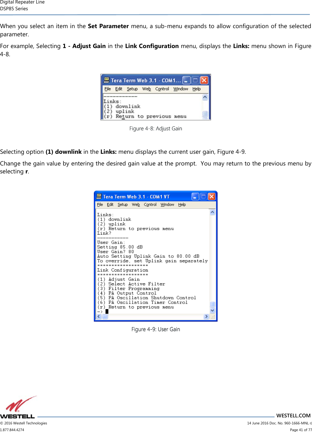
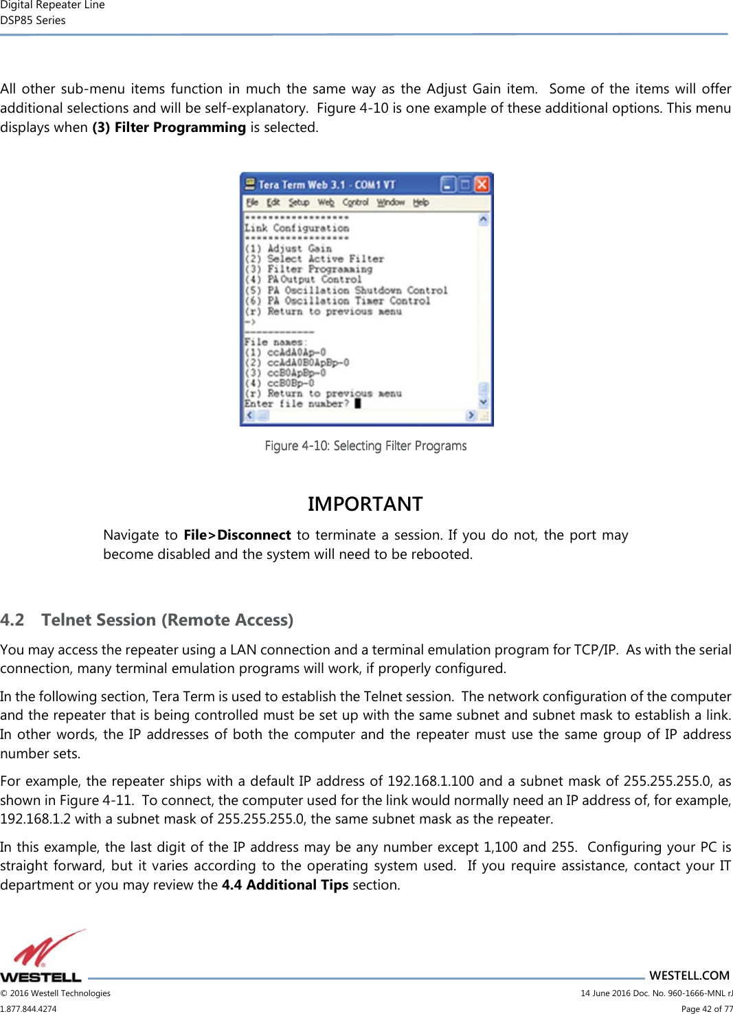
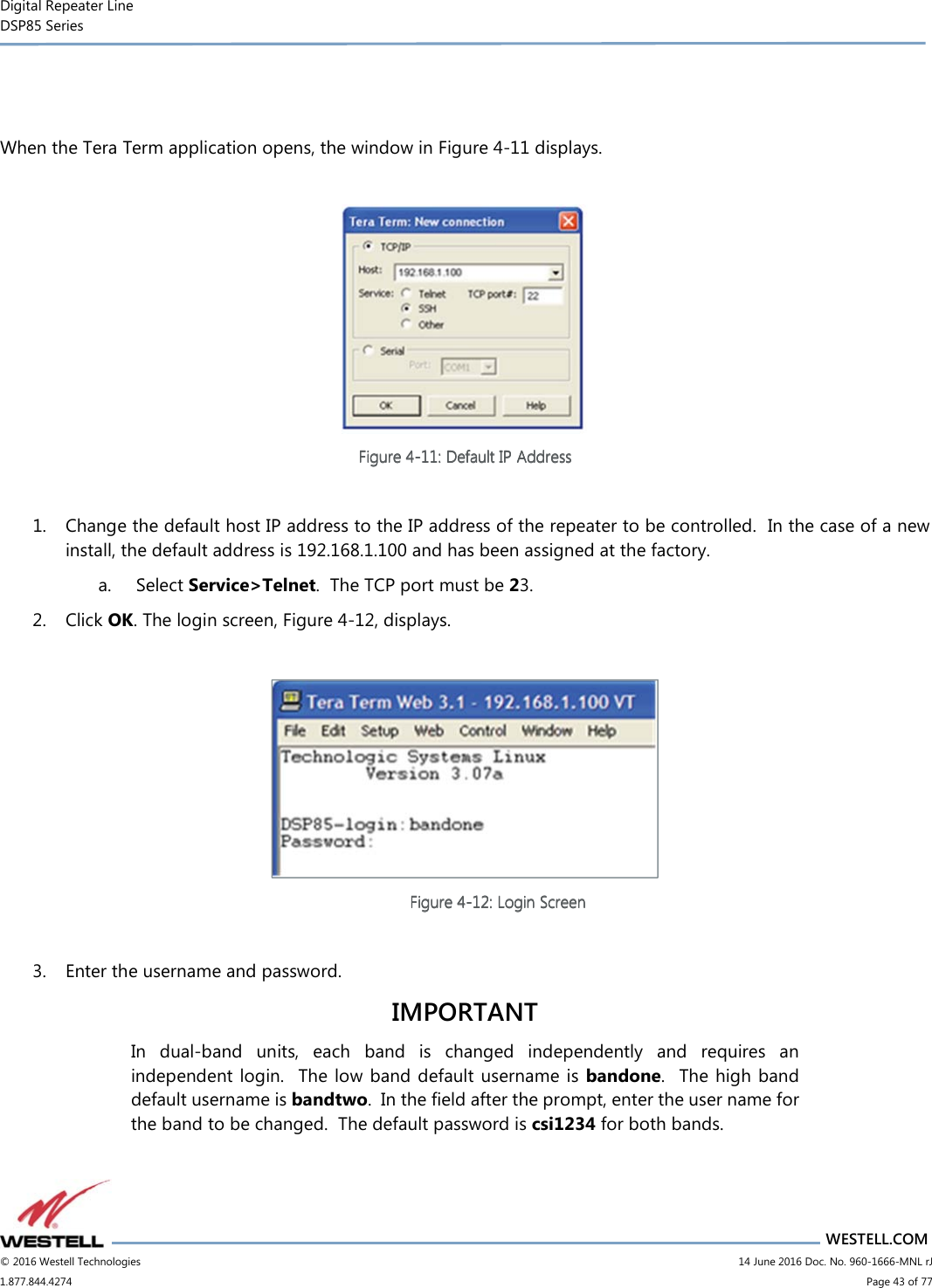
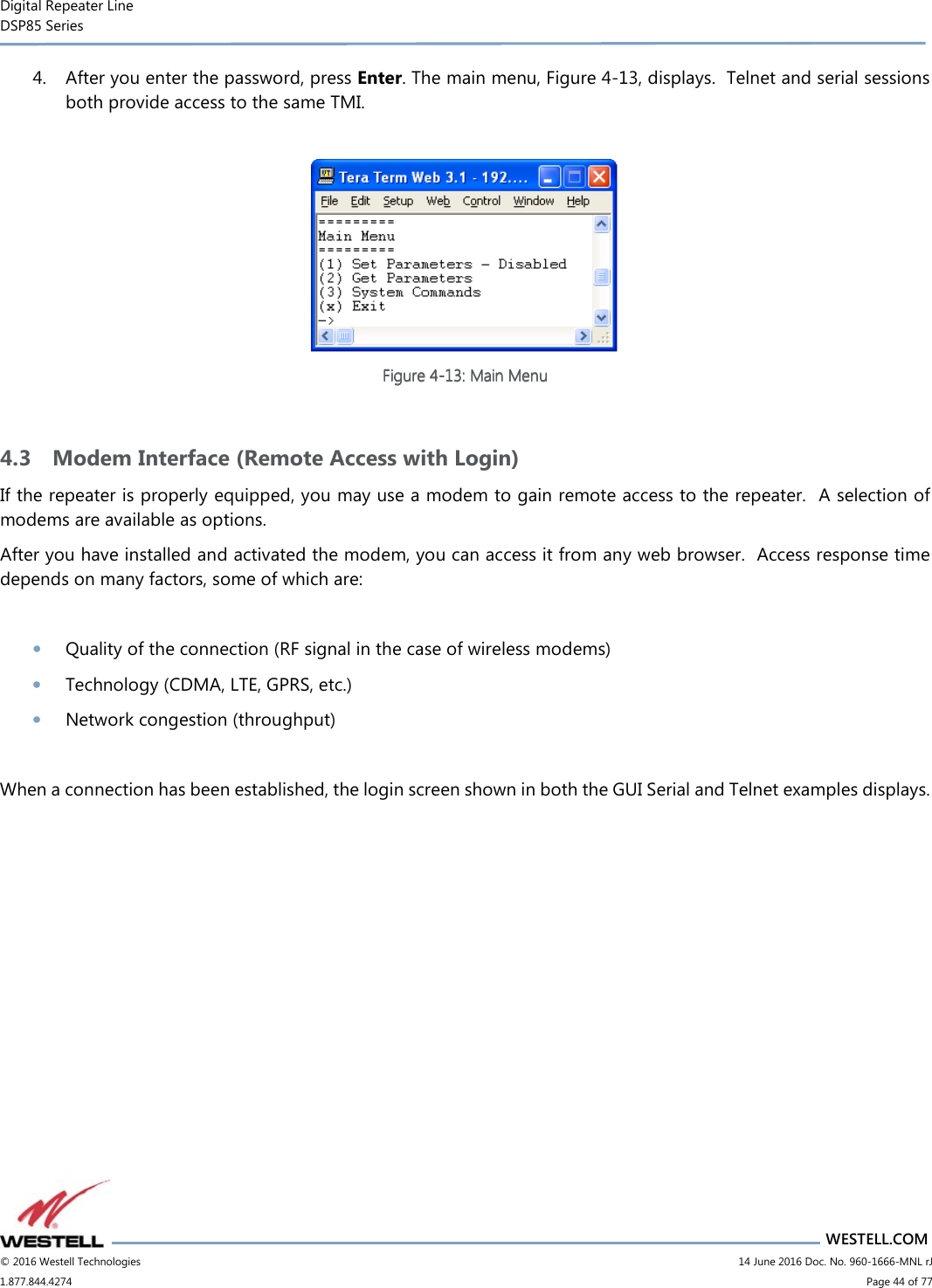
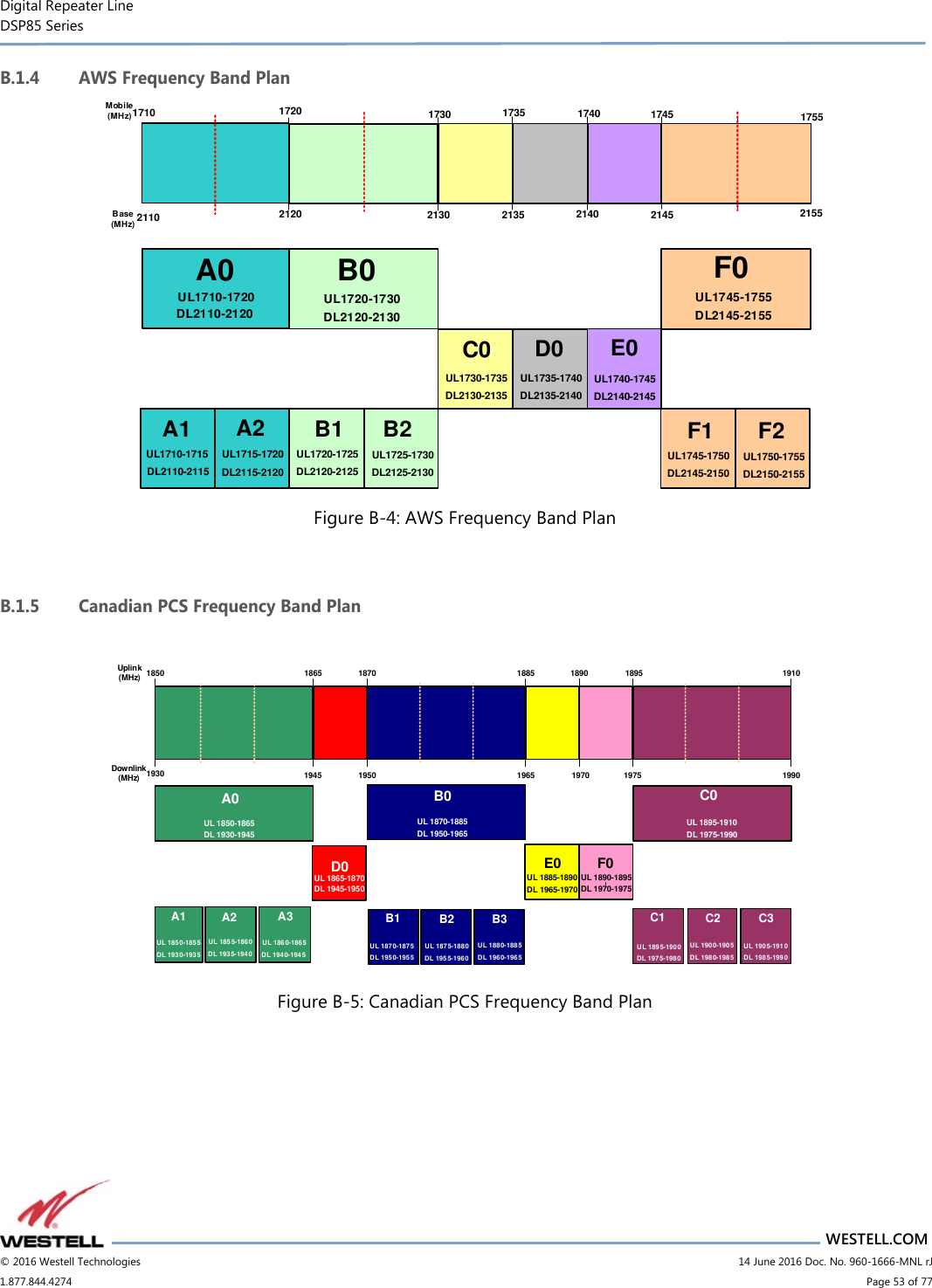
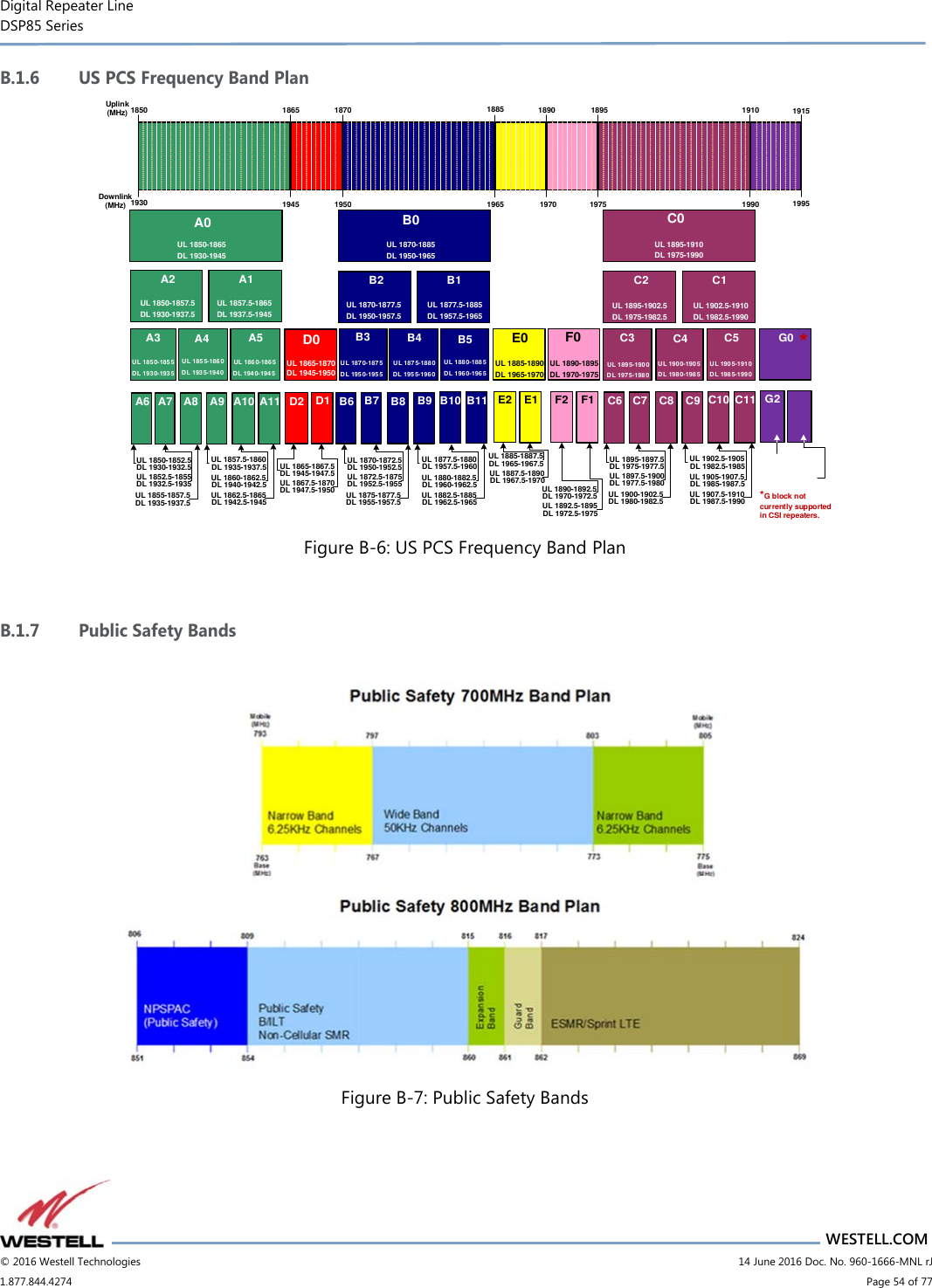
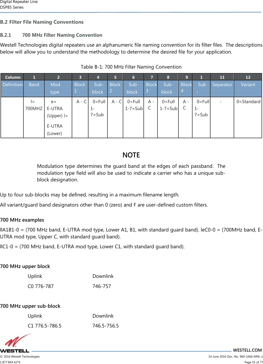
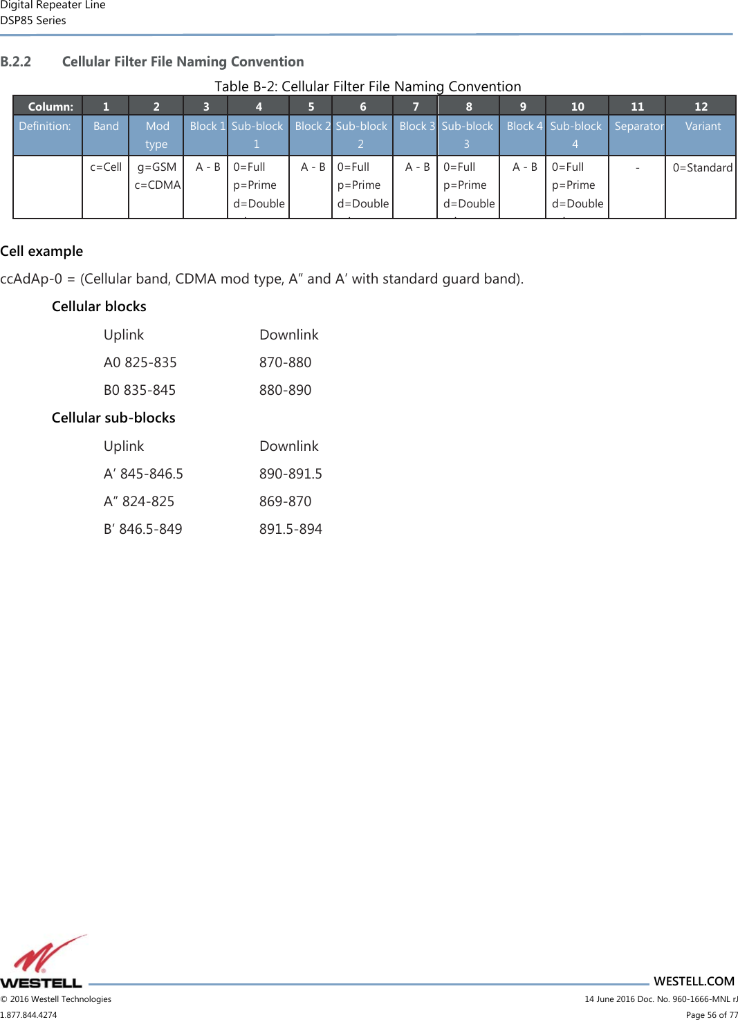
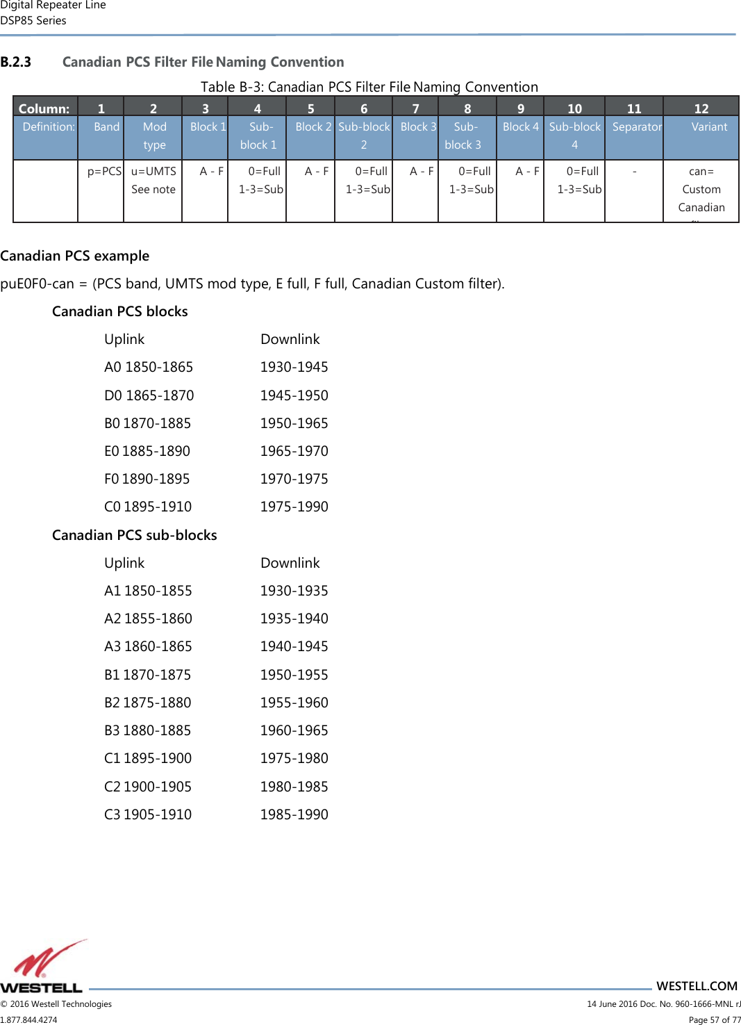
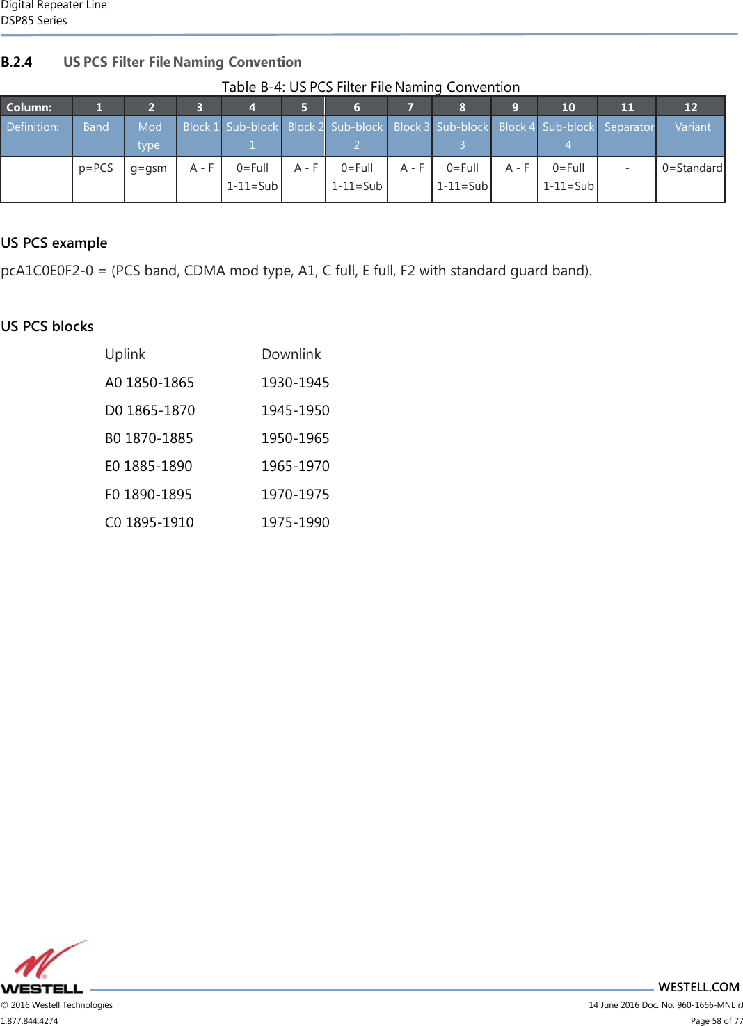
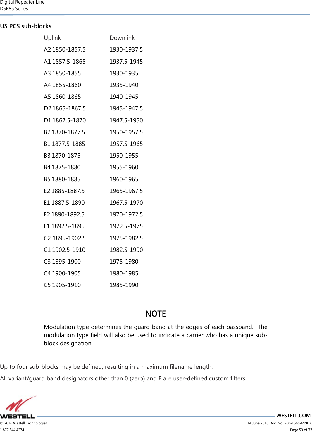
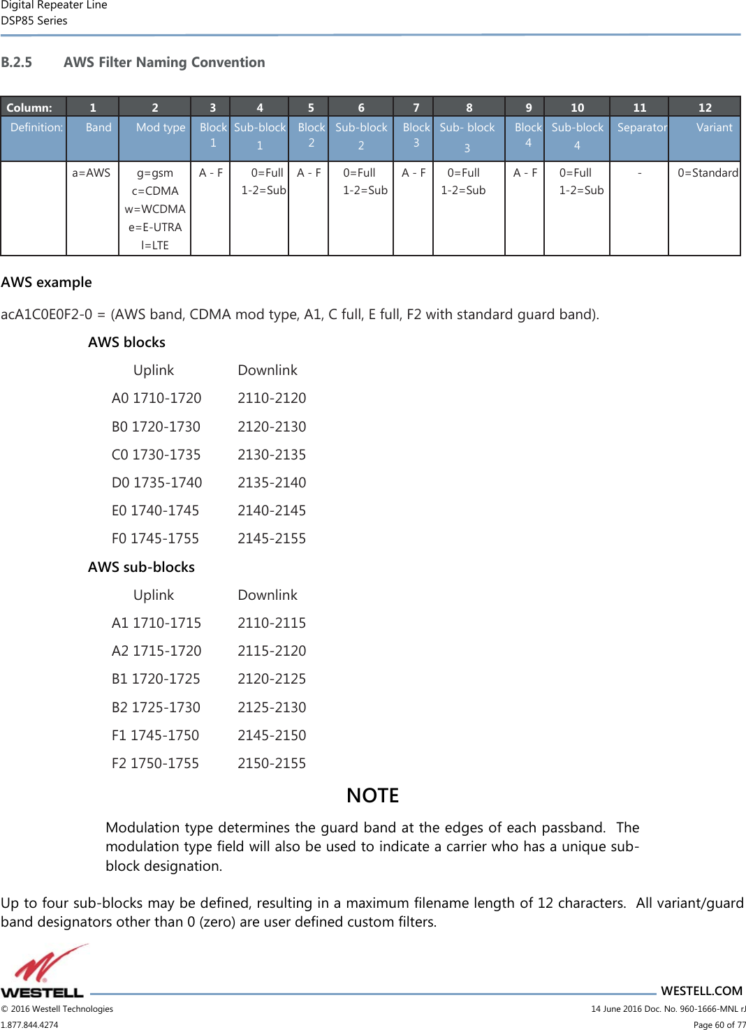
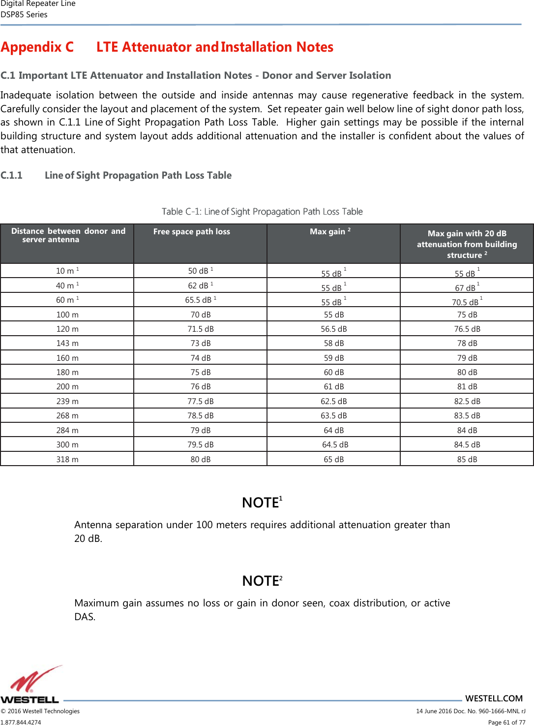
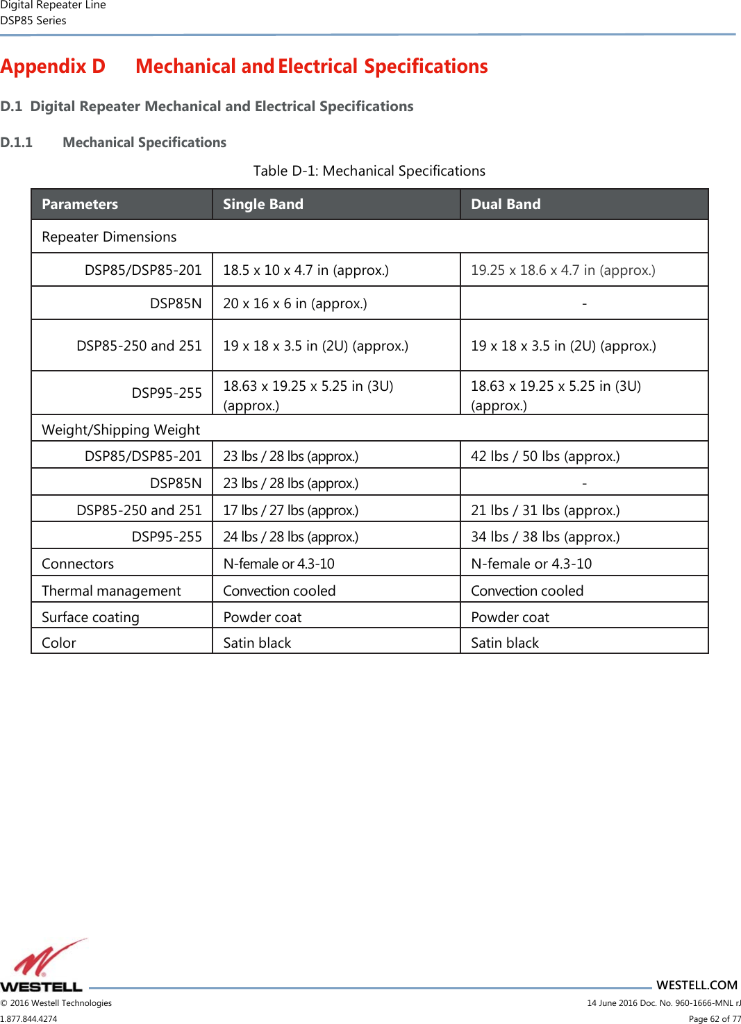
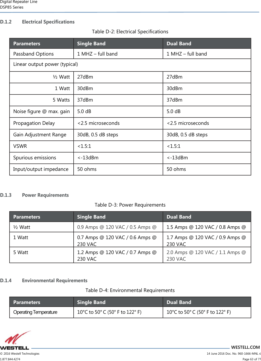
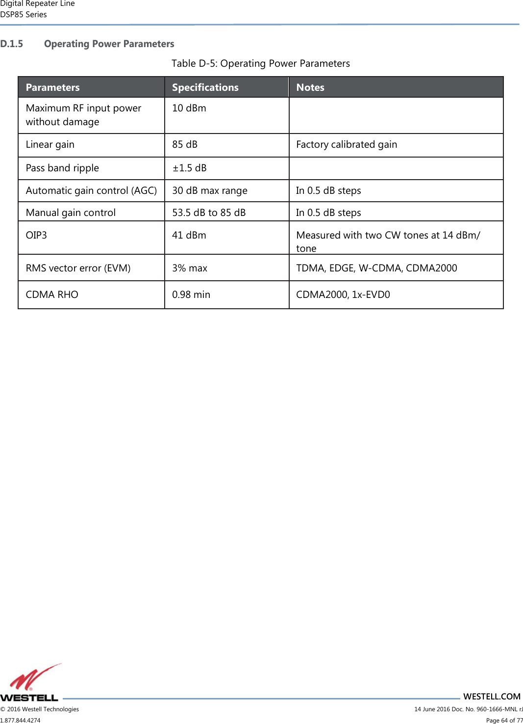
User Manual
Discussion / Help
Navigation