Westell DSP85-L7U7C Digital Repeater User Manual NVRDSP85 L7U7C UserMan rJ3
Westell, Inc. Digital Repeater NVRDSP85 L7U7C UserMan rJ3
Westell >
User Manual

PRODUCT M
A
N
UAL
WESTELL.COM
©Westell Technologies
.
960-1666-MNL
r4
DSP85 Series Digital Repeater
User’s Guide

Digital Repeater Line
DSP85 Series
WESTELL.COM
© 2016 Westell Technologies 20 March 2017 Doc. No. 960-1666-MNL r4
1.877.844.4274 Page 2 of 77
DISCLAIMER
All information and statements contained herein are accurate to the best of Westell Technologies knowledge. Westell
Technologies makes no warranty with respect there to, including without limitation any results that may be obtained
from the products described herein or the infringement by such products of any property rights of any persons. Use
or application of such information or statements is at the users’ sole risk, without any liability on the part of Westell
Technologies. Nothing herein shall be construed as license or recommendation for use, which infringes upon any
propriety rights of any person. Product material and specifications are subject to change without notice. Westell
Technologies standard terms of sale and the specific terms of any particular sale apply.
WARNING. This is NOT a CONSUMER device. It is designed for installation by FCC LICENSEES and QUALIFIED
INSTALLERS. You must have an FCC LICENSE or express consent of an FCC Licensee to operate this
device. Unauthorized use may result in significant forfeiture penalties, including penalties in excess of $100,000 for
Each continuing violation.”
WARNING! Changes and Modifications not expressly approved by Westell can void your authority to operate this
equipment under Federal Communications Commission’s rules.
WARNING! The Manufacturer's rated output power of this equipment is for single carrier operation. For situations
when multiple carrier signals are present, the rating would have to be reduced by 3.5 dB, especially where the
output signal is re-radiated and can cause interference to adjacent band users. This power reduction is to be by
means of input power or gain reduction and not by an attenuator at the output of the device.

Digital Repeater Line
DSP85 Series
WESTELL.COM
© 2016 Westell Technologies 20 March 2017 Doc. No. 960-1666-MNL r4
1.877.844.4274 Page 3 of 77
TABLE OF CONTENTS
Preface ............................................................................................................................................................................... ix
Purpose.................................................................................................................................................................................................................. ix
Application ........................................................................................................................................................................................................... ix
Document Organization ................................................................................................................................................................................. ix
Document Conventions ................................................................................................................................................................................... x
Product Registration Information ............................................................................................................................................................... xi
Safety Guidelines ............................................................................................................................................................................................... xi
Important Safety Information ....................................................................................................................................................................... xi
Industry Certifications/Registration Numbers ...................................................................................................................................... xii
Canadian Compliance Information............................................................................................................................................................ xii
Technical Support............................................................................................................................................................................................ xiii
Acronyms and Abbreviations ...................................................................................................................................................................... xiii
1 Product Overview ................................................................................................................................................... 13
1.1 Product Information ........................................................................................................................................................................ 13
1.2 Functional Overview........................................................................................................................................................................ 13
1.3 LED Indicator ...................................................................................................................................................................................... 14
1.4 Local Communication Interface Ports ...................................................................................................................................... 15
1.5 EIA232 Pin Specifications .............................................................................................................................................................. 15
1.6 USB Interface ..................................................................................................................................................................................... 15
1.7 Ethernet ................................................................................................................................................................................................ 16
1.8 Monitoring and Alarms .................................................................................................................................................................. 16
1.9 Circuit Operational Description .................................................................................................................................................. 16
1.10 Functional Block Diagrams ........................................................................................................................................................... 16
2 Optimizing the System during Installation ........................................................................................................ 19
2.1 System Setup Considerations ..................................................................................................................................................... 19
2.2 Suggested Spectrum Analyzer Setting .................................................................................................................................... 19
2.3 Important Installation Notes ....................................................................................................................................................... 20
2.4 Installation Guidelines .................................................................................................................................................................... 20
2.4.1 Donor Antenna ............................................................................................................................................................................ 20
2.4.2 Antennas ......................................................................................................................................................................................... 21
2.5 Optional Accessories ...................................................................................................................................................................... 21
2.5.1 Outside Donor Antenna ........................................................................................................................................................... 21
2.5.2 Inside Omnidirectional Antenna ........................................................................................................................................... 21

Digital Repeater Line
DSP85 Series
WESTELL.COM
© 2016 Westell Technologies 20 March 2017 Doc. No. 960-1666-MNL r4
1.877.844.4274 Page 4 of 77
2.5.3 Power Dividers ............................................................................................................................................................................. 21
2.5.4 Grounding Kit ............................................................................................................................................................................... 21
2.5.5 Directional Couplers .................................................................................................................................................................. 22
2.5.6 19” Rack Shelf ............................................................................................................................................................................... 22
2.5.7 UPS.................................................................................................................................................................................................... 22
2.5.8 Cross Band Couplers .................................................................................................................................................................. 22
3 Web-based GUI ....................................................................................................................................................... 23
3.1 Web-based GUI Session ................................................................................................................................................................ 23
3.2 System Status .................................................................................................................................................................................... 24
3.3 Local Network .................................................................................................................................................................................... 25
3.4 RF Configuration .............................................................................................................................................................................. 26
3.5 Program a Filter ................................................................................................................................................................................ 27
3.6 Remote Network .............................................................................................................................................................................. 28
3.7 SNMP Configuration ....................................................................................................................................................................... 29
3.8 Time Configuration ......................................................................................................................................................................... 29
3.9 System Health.................................................................................................................................................................................... 30
3.10 Install and Upload ............................................................................................................................................................................ 31
3.11 Reboot .................................................................................................................................................................................................. 32
3.12 Alarm Configuration ....................................................................................................................................................................... 33
3.13 Email Configuration......................................................................................................................................................................... 34
3.14 Log Configuration ............................................................................................................................................................................ 35
3.15 Account Credentials ........................................................................................................................................................................ 36
4 Console Interface .................................................................................................................................................... 37
4.1 Text Menu Interface (Local Access) ........................................................................................................................................... 37
4.2 Telnet Session (Remote Access) ................................................................................................................................................. 42
4.3 Modem Interface (Remote Access with Login) .................................................................................................................... 44
4.4 Additional Tips .................................................................................................................................................................................. 45
Appendix A Attenuation and Dynamic Range Guidelines ................................................................................. 49
A.1 Donor Port .......................................................................................................................................................................................... 49
A.2 Server Port .......................................................................................................................................................................................... 49
A.3 Dynamic Range Thresholds ......................................................................................................................................................... 50
A.4 Large Deltas between In-band and Composite Input Signals ....................................................................................... 50
Appendix B
Band Plans
and Filter File Naming Conventions ................................................................................. 51
B.1 Frequency Band Plans .................................................................................................................................................................... 51
B.1.1 700 MHz Lower A, B and C Band Plan ................................................................................................................................ 51

Digital Repeater Line
DSP85 Series
WESTELL.COM
© 2016 Westell Technologies 20 March 2017 Doc. No. 960-1666-MNL r4
1.877.844.4274 Page 5 of 77
B.1.2 700 MHz Upper C Band Plan .................................................................................................................................................. 52
B.1.3 Cellular Frequency Band Plan ................................................................................................................................................. 52
B.1.4 AWS Frequency Band Plan ...................................................................................................................................................... 53
B.1.5 Canadian PCS Frequency Band Plan .................................................................................................................................... 53
B.1.6 US PCS Frequency Band Plan ................................................................................................................................................. 54
B.1.7 Public Safety Bands .................................................................................................................................................................... 54
B.2 Filter File Naming Conventions .................................................................................................................................................. 55
B.2.1 700 MHz Filter Naming Convention .................................................................................................................................... 55
B.2.2 Cellular Filter File Naming Convention ............................................................................................................................... 56
B.2.3 Canadian PCS Filter File Naming Convention .................................................................................................................. 57
B.2.4 US PCS Filter File Naming Convention ................................................................................................................................ 58
B.2.5 AWS Filter Naming Convention ............................................................................................................................................ 60
Appendix C LTE Attenuator and Installation Notes ................................................................................................ 61
C.1 Important LTE Attenuator and Installation Notes - Donor and Server Isolation .................................................... 61
C.1.1 Line of Sight Propagation Path Loss Table ........................................................................................................................ 61
Appendix D Mechanical and Electrical Specifications ........................................................................................ 62
D.1 Digital Repeater Mechanical and Electrical Specifications .............................................................................................. 62
D.1.1 Mechanical Specifications .................................................................................................................................................. 62
D.1.2 Electrical Specifications........................................................................................................................................................ 63
D.1.3 Power Requirements ............................................................................................................................................................ 63
D.1.4 Environmental Requirements ............................................................................................................................................ 63
D.1.5 Operating Power Parameters ............................................................................................................................................ 64
Appendix E Port Configurations ............................................................................................................................... 65
E.1 Digital Repeater Port Configurations, Original Series ....................................................................................................... 65
E.1.1 Dual-band D2:D1 Port Configuration ................................................................................................................................. 65
E.1.2 Dual-band D1:D2 Port Configuration ................................................................................................................................. 65
E.1.3 Dual-band D2: D2 Port Configuration ................................................................................................................................ 66
E.1.4 Dual-band D1:D1 Port Configuration ................................................................................................................................. 66
E.1.5 Single-band D1:D1 Port Configuration .............................................................................................................................. 67
E.1.6 Dual-band D2:S4 Port Configuration .................................................................................................................................. 67
E.1.7 Dual-band D1:S4 Port Configuration .................................................................................................................................. 68
E.1.8 Single-band D1:S2 Port Configuration ............................................................................................................................... 68
E.2 Digital Repeater Port Configurations ....................................................................................................................................... 69
E.2.1 Dual-band D2:D1 Port Configuration ................................................................................................................................. 69
E.2.2 Dual-band D1:D2 Port Configuration ................................................................................................................................. 69
E.2.3 Dual-band D2:D2 Port Configuration ................................................................................................................................. 70

Digital Repeater Line
DSP85 Series
WESTELL.COM
© 2016 Westell Technologies 20 March 2017 Doc. No. 960-1666-MNL r4
1.877.844.4274 Page 6 of 77
E.2.4 Dual-band D1:D1 Port Configuration ................................................................................................................................. 70
E.2.5 MIMO Port Configuration ........................................................................................................................................................ 70
E.2.6 Single-band D1:D1 Port Configuration .............................................................................................................................. 71
E.2.7 Dual-band D2:S4 Port Configuration .................................................................................................................................. 71
E.2.8 Dual-band D1:S4 Port Configuration .................................................................................................................................. 72
E.2.9 Single-band D1:S2 Port Configuration ............................................................................................................................... 72
Appendix F Mechanical Configurations ................................................................................................................... 73
F.1 DSP85-250 and DSP85-251 Series Mechanical Drawing ................................................................................................. 73
F.2 DSP85-250 and DSP85-251 Series Mounting ....................................................................................................................... 74
Appendix G Acronyms and Abbreviations ........................................................................................................... 76
TABLE OF FIGURES
Figure P-1: Product Registration Information .............................................................................................................................................. xi
Figure 1-1: DB-9 Pin Descriptions ................................................................................................................................................................. 15
Figure 1-2: Dual Band Functional Block Diagram ..................................................................................................................................... 17
Figure 1-3: Single Band Functional Block Diagram .................................................................................................................................. 18
Figure 3-1: User Connection Login ................................................................................................................................................................. 23
Figure 3-2: System Status ................................................................................................................................................................................... 24
Figure 3-3: Local Network .................................................................................................................................................................................. 25
Figure 3-4: RF Configuration ............................................................................................................................................................................. 26
Figure 3-5: Program a Filter .............................................................................................................................................................................. 27
Figure 3-6: Remote Network............................................................................................................................................................................. 28
Figure 3-7: SNMP Configuration ..................................................................................................................................................................... 29
Figure 3-8: Time Configuration ........................................................................................................................................................................ 29
Figure 3-9: System Health .................................................................................................................................................................................. 30
Figure 3-10: Install & Upload............................................................................................................................................................................ 31
Figure 3-11: Reboot .............................................................................................................................................................................................. 32
Figure 3-12: Alarm Configuration ................................................................................................................................................................... 33
Figure 3-13: Email Configuration .................................................................................................................................................................... 34
Figure 3-14: Log Configuration ........................................................................................................................................................................ 35
Figure 3-15: Account Credentials .................................................................................................................................................................... 36
Figure 4-1: Null Modem Cable ......................................................................................................................................................................... 37

Digital Repeater Line
DSP85 Series
WESTELL.COM
© 2016 Westell Technologies 20 March 2017 Doc. No. 960-1666-MNL r4
1.877.844.4274 Page 7 of 77
Figure 4-2: Gender Adapter .............................................................................................................................................................................. 37
Figure 4-3: Tera Term Pro Web Start Up ...................................................................................................................................................... 37
Figure 4-4: Serial Radio Button ........................................................................................................................................................................ 38
Figure 4-5: Setup ................................................................................................................................................................................................... 38
Figure 4-6: Serial Port Setup ............................................................................................................................................................................. 39
Figure 4-7: TMI Menus ........................................................................................................................................................................................ 40
Figure 4-8: Adjust Gain........................................................................................................................................................................................ 41
Figure 4-9: User Gain ........................................................................................................................................................................................... 41
Figure 4-10: Selecting Filter Programs .......................................................................................................................................................... 42
Figure 4-11: Default IP Address ....................................................................................................................................................................... 43
Figure 4-12: Login Screen .................................................................................................................................................................................. 43
Figure 4-13: Main Menu ..................................................................................................................................................................................... 44
Figure 4-14: Control Panel ................................................................................................................................................................................. 45
Figure 4-15: View Network Status and Tasks ............................................................................................................................................. 45
Figure 4-16: Change Adapter Settings.......................................................................................................................................................... 46
Figure 4-17: Local Area Network ..................................................................................................................................................................... 46
Figure 4-18: Internet Protocol Version 4 (TCP/IPv4) ............................................................................................................................... 47
Figure 4-19: Enter IP Address ........................................................................................................................................................................... 47
TABLE OF TABLES
Table P-1: Document Conventions .................................................................................................................................................................... x
Table A-1: Dynamic Range Thresholds ......................................................................................................................................................... 50
Table B-1:
700 MHz Filter Naming
Convention ........................................................................................................................................... 55
Table B-2: Cellular Filter File Naming Convention.................................................................................................................................... 56
Table B-3:
Canadian PCS Filter
File
Naming
Convention .......................................................................................................................... 57
Table B-4: US
PCS Filter
File
Naming
Convention ....................................................................................................................................... 58
Table C-1: Line of Sight Propagation Path Loss Table ............................................................................................................................ 61
Table D-1: Mechanical Specifications ............................................................................................................................................................ 62
Table D-2: Electrical Specifications ................................................................................................................................................................. 63
Table D-3: Power Requirements ...................................................................................................................................................................... 63
Table D-4: Environmental Requirements ..................................................................................................................................................... 63

Digital Repeater Line
DSP85 Series
WESTELL.COM
© 2016 Westell Technologies 20 March 2017 Doc. No. 960-1666-MNL r4
1.877.844.4274 Page 8 of 77
Table D-5: Operating Power Parameters ......................................................................................................................................................64
Table G-1: Acronyms and Abbreviations ..................................................................................................................................................... 76

Digital Repeater Line
DSP85 Series
WESTELL.COM
© 2016 Westell Technologies 20 March 2017 Doc. No. 960-1666-MNL r4
1.877.844.4274 Page 9 of 77
Preface
This Preface includes the following:
• Purpose
• Application
• Document Organization
• Document Conventions
• Product Registration Information
• Safety Guidelines
• Important Safety Information
• Industry Certifications/Registration Numbers
• Technical Support
• Acronyms and Abbreviations
Purpose
The purpose of this document is to provide a procedure to help experienced technicians/engineers install and
commission an in-building wireless enhancement repeater system using Westell Technologies digital repeaters. This
document was written to address the practical concerns of the installer. Following the procedures in this manual will
minimize risks associated with modifying a live system and will prevent service interruptions. This document assumes
the technician/engineer understands the basic principles and functionality involved with repeater and in-building
systems.
Application
Apply this
guide when
adding
digital repeater capability
to an
existing system
or
as part of a
new installation.
Document Organization
This manual includes the following chapters:
Chapter 1: Product Overview – Provides an overview of the DSP85 Repeater Series
Chapter 2: Optimizing the System during Installation – Provides information for optimization of the system
Chapter 3: Web-Based GUI – Provides information about using the system through a web-based graphical user
interface
Chapter 4: Console Interface – Provides information about local access to the repeater through console interface
Appendix A: Attenuation and Dynamic Range Guidelines – Provides information about attenuation and dynamic
range guidelines
Appendix B: Band Plans and Filter File Naming Conventions – Provides information about the band plans and filter
file naming conventions

Digital Repeater Line
DSP85 Series
WESTELL.COM
© 2016 Westell Technologies 20 March 2017 Doc. No. 960-1666-MNL r4
1.877.844.4274 Page 10 of 77
Appendix C: LTE Attenuator and Installation Notes – Provides the LTE Attenuator and installation notes including
donor and server isolation
Appendix D: Mechanical and Electrical Specifications– Provides mechanical and electrical specifications for this
product
Appendix E: Port Configurations – Details and illustrates the port configurations for each repeater type
Appendix F: Mechanical Configurations – Details and illustrates the mechanical configuration for each repeater type
Appendix G: Acronyms and Abbreviations – Provides a table of acronyms and abbreviations used in this manual and
a definition for each
Document Conventions
Table P-1 lists the conventions used throughout this document.
Table P
Table PTable P
Table P-
--
-1
11
1:
::
:
Document Conventions
Document ConventionsDocument Conventions
Document Conventions
Convention Description
DANGER! Description of an imminent hazard that, if not avoided, may result in severe injury or death.
WARNING! Description of an imminent hazard that, if not avoided, may result in injury or serious
equipment damage.
CAUTION Description of an imminent hazard that, if not avoided, could result in equipment damage.
IMPORTANT Additional information that is very important for the user to know. More critical than a note,
but does not contain a Danger!, Warning! or Caution.
NOTE Additional information or comments that may be beneficial for the user to know.
Bold Bold typeface indicates commands, buttons, keyboard keys, user interface elements, and
provides emphasis.
Command1 >
Command2
The > symbol between commands indicates a succession of commands. For example, select
Start > Settings.
Key1+Key2 A plus sign between key names indicates simultaneous keyboard commands. Press and
hold down the first key while pressing the second key. For example, Ctrl+X.
Digital Repeater Line
DSP85 Series
WESTELL.COM
© 2016 Westell Technologies 20 March 2017 Doc. No. 960-1666-MNL r4
1.877.844.4274 Page 11 of 77
Product Registration Information
The product serial number is located on the label on the bottom panel, near the power connectors. Record the serial
number, model number, purchase date and point-of-sale company in the boxes in Figure P-1 below. Retain this
manual, along with proof of purchase, to serve as a permanent record of your purchase.
Fig
FigFig
Figure P
ure Pure P
ure P-
--
-1
11
1: Product Registration Information
: Product Registration Information: Product Registration Information
: Product Registration Information
Safety Guidelines
The general safety information in this section applies to both operating and service personnel. Specific warnings and
cautions are located in other parts of this manual to which they apply, but may not appear in this summary. Failure
to comply with these precautions or specific warnings elsewhere in the manual violates safety standards of design,
manufacture, and intended use of equipment. Westell Technologies assumes no liability for the customer’s failure to
comply with these requirements:
Grounding: This digital repeater system is designed to operate from 100 - 240 VAC and must always be operated
with the ground wire properly connected. Do not remove or otherwise alter the grounding lug on the power cord.
Explosive atmospheres: To avoid explosion or fire, do not operate this product in the presence of flammable gases
or fumes.
Lightning danger: Do not install or adjust this unit during an electrical storm. We strongly recommend the use of a
suitable lightning arrester.
There are no user-serviceable parts inside the repeater.
DANGER!
Hazardous voltages are present when the cover is removed. Do not open the
repeater enclosure. If you suspect a malfunction with this product, call your dealer
or call Westell Technologies technical support line at 1.877.844.4274.
WARNING!
Disconnect/remove power before connecting or disconnecting cables.
Important Safety Information
Antennas used to radiate signals indoors are limited to a maximum gain of 3 dBi. The outdoor antenna used to
communicate to the wireless infrastructure is limited to 14dBi gain, or any combination of gain and loss that equals
14 dB at input. Position each antenna to observe minimum separation requirements from all users and bystanders.

Digital Repeater Line
DSP85 Series
WESTELL.COM
© 2016 Westell Technologies 20 March 2017 Doc. No. 960-1666-MNL r4
1.877.844.4274 Page 12 of 77
Use the following guidelines when considering separation distances.
• Place indoor antennas such that, under normal conditions, personnel cannot come within 20 cm (~8
in) from any inside antenna. Adhering to this minimum separation ensures that bystanders cannot
exceed RF exposures beyond the maximum permissible limit for uncontrolled exposure.
• Position outdoor antennas such that, under normal conditions, personnel cannot approach closer
than 183 cm (~6 ft.). If a directional antenna that has a maximum gain of 14 dBi is used, take
precautions to prevent personnel from routinely passing through the main radiation beam at a
distance closer than specified.
WARNING. This is NOT a CONSUMER device. It is designed for installation by FCC LICENSEES and QUALIFIED
INSTALLERS. You must have an FCC LICENSE or express consent of an FCC Licensee to operate this
device. Unauthorized use may result in significant forfeiture penalties, including penalties in excess of $100,000 for
each continuing violation.”
WARNING! Changes and Modifications not expressly approved by Westell can void your authority to operate this
equipment under Federal Communications Commission’s rules.
Industry Certifications/Registration Numbers
FCC
• NVRCSI-DSP85-C/P, NVRCSI-DSP85201CP, NVRCSI-DSP85-U7C, NVRCSI-DSP85-PS7, NVRCSI-
DSP85-PSS8, NVRCSI-DSP25XCP, NVR-DSP251AWS, NVRCSI-DSP25XAWS, NVRCSI-DSP25XS8,
NVRCSI-DSP25XL7, NVRDSP-PCSGAWS3, NVRDSP-PCSG, NVRDSP-AWS3, NVRDSP85-L7C,
NVRDSP85-L7PG, NVRDSP85-L7U7C, NVRDSP85-CPG, NVRDSP85-U7CPG
IC
• 4307A-DSP25XHCP, 4307A-DSP25XS8, 4307A-DSP251AWS, 4307A-DSP85L7C, 4307A-DSP85L7U7C,
4307A-DSP85L7PG, 4307A-DSP85CPG, 4307A-DSP85U7CPG
UL
• Power supply: UL60950-1
Canadian Compliance Information
This device complies with Industry Canada license-exempt RSS standard(s). Operation is subject to the following
two conditions: (1) this device may not cause interference, and (2) this device must accept any interference,
including interference that may cause undesired operation of the device.
Le présent appareil est conforme aux CNR d'Industrie Canada applicables aux appareils radio exempts de licence.
L'exploitation est autorisée aux deux conditions suivantes : (1) l'appareil ne doit pas produire de brouillage, et (2)
l'utilisateur de l'appareil doit accepter tout brouillage radioélectrique subi, même si le brouillage est susceptible d'en
compromettre le fonctionnement.

Digital Repeater Line
DSP85 Series
WESTELL.COM
© 2016 Westell Technologies 20 March 2017 Doc. No. 960-1666-MNL r4
1.877.844.4274 Page 13 of 77
Technical Support
If you suspect a malfunction with this product or if you have a technical question, call your dealer or the Westell
Technologies In-Building Wireless Support Line at (603) 626-6677, Toll Free (USA) 1-877-844-4274, press option 2
then option 1, or email us at ibwsupport@westell.com.
Acronyms and Abbreviations
Refer to the Appendix G at the end of this manual for definitions of the acronyms and abbreviations used in this
manual.
1
Product Overview
1.1 Product Information
Westell Technologies digital repeaters were developed for use within enclosed structures where sufficient signal
strength from local cell sites to operate cell phones is unavailable. Adequate signal strength must be available outside
the structure as a prerequisite to achieving in-building coverage. The digital repeater is connected to an external
antenna, usually on the roof, and to one or more internal antennas placed strategically throughout the area where
wireless service is desired.
The external antenna is typically a directional type, such as a Yagi antenna. Internal antennas are typically
omnidirectional, though various other types may be used, depending on the coverage application. The Westell DSP
repeater amplifies both the uplink (phone to tower) and downlink (tower to phone) signals, facilitating
communications to and from the intended wireless infrastructure.
With a maximum total of 85 dB nominal gain on both the uplink and downlink, gain can be adjusted over a range
from 53.5 dB to 85 dB in 0.5 dB steps. The repeater is controlled with a computer connected to COM port 1 or 2 or
via a crossover ethernet cable connected to the ethernet port.
A specific filtering process modifies each amplification chain. This process digitally converts the assigned spectrum
and then applies digital signal processing (DSP) techniques. DSP is used to create passbands that selects the RF
energy passing through either the uplink or downlink paths. After the digital processing is complete, the information
is converted back to an analog signal that is applied to the remaining stages of amplification. The resulting signals
emitted by the repeater are specific to the network service providers’ requirements. If these requirements change,
only the DSP configuration parameters must change. Configuration parameters are created at the factory and
supplied as files to be downloaded to the repeater. The filter set configurations stored in memory determine the
unit’s adaptability to various field applications. Appendix B describes the band plans and the convention Westell uses
to identify and store the files that make up the filter set. All Westell repeaters are shipped with an active filter set that
is programmed according to customer specifications. In most cases, the installer will not be required to program a
filter.
1.2 Functional Overview
Westell Technologies digital repeaters incorporate the following features for convenient operation, access, protection,
and control:
• Network configuration and control using either a web GUI accessed using a web browser or a menu
driven user interface using the serial port. The GUI does not require Internet access.

Digital Repeater Line
DSP85 Series
WESTELL.COM
© 2016 Westell Technologies 14 June 2016 Doc. No. 960-1666-MNL rJ
1.877.844.4274 Page 14 of 77
• User gain control (affects all passbands)
• Automatic gain control
• Automatic power control
• Overdrive protection (PA limiting)
• Under/Over voltage protection
• Fault protection
• Alarm notification - local/remote
• Upgrade support - local/remote
• External interfaces - USB/ethernet/Serial
• Re-loadable filters - local/remote
• Web-based monitoring and control - local/remote
• Persistent status and error information
1.3 LED Indicator
Westell Technologies automatic safety precautions are built into the amplifier system. In the case of a catastrophic
system event, a shutdown circuit will disable all emissions if the uplink input or downlink input is overdriven or if an
oscillation or output overpower event occurs. The amplifier will periodically attempt to recover from the detected
condition.
Status LED states are:
• Blinking yellow: Unit is migrating the database after an upgrade
• Blinking red: Unit is programming the filter(s) and there is an error condition
• Blinking green: Boot up or unit is programming the filter(s) and no error condition exists
• Solid green: Unit is operational, PA is on
• Solid yellow: Unit is operational, but AGC is on
• Solid red: Unit has an error condition or PA is off
• Dark: Unit is not powered
Check the GUI status page for the nature of the fault.
NOTE
On power up, the repeater requires approximately three minutes for the internal
computer to boot. During this time, the LED labeled Power/Fault or Status will slowly
blink green on and off at a rate of approximately 1 Hz. This will indicate that the unit
Digital Repeater Line
DSP85 Series
WESTELL.COM
© 2016 Westell Technologies 14 June 2016 Doc. No. 960-1666-MNL rJ
1.877.844.4274 Page 15 of 77
is in the boot up process. A blinking green LED (two seconds on/three seconds off)
indicates a filter configuration file is loading.
IMPORTANT
Do not unplug the repeater while it is in the boot-up process.
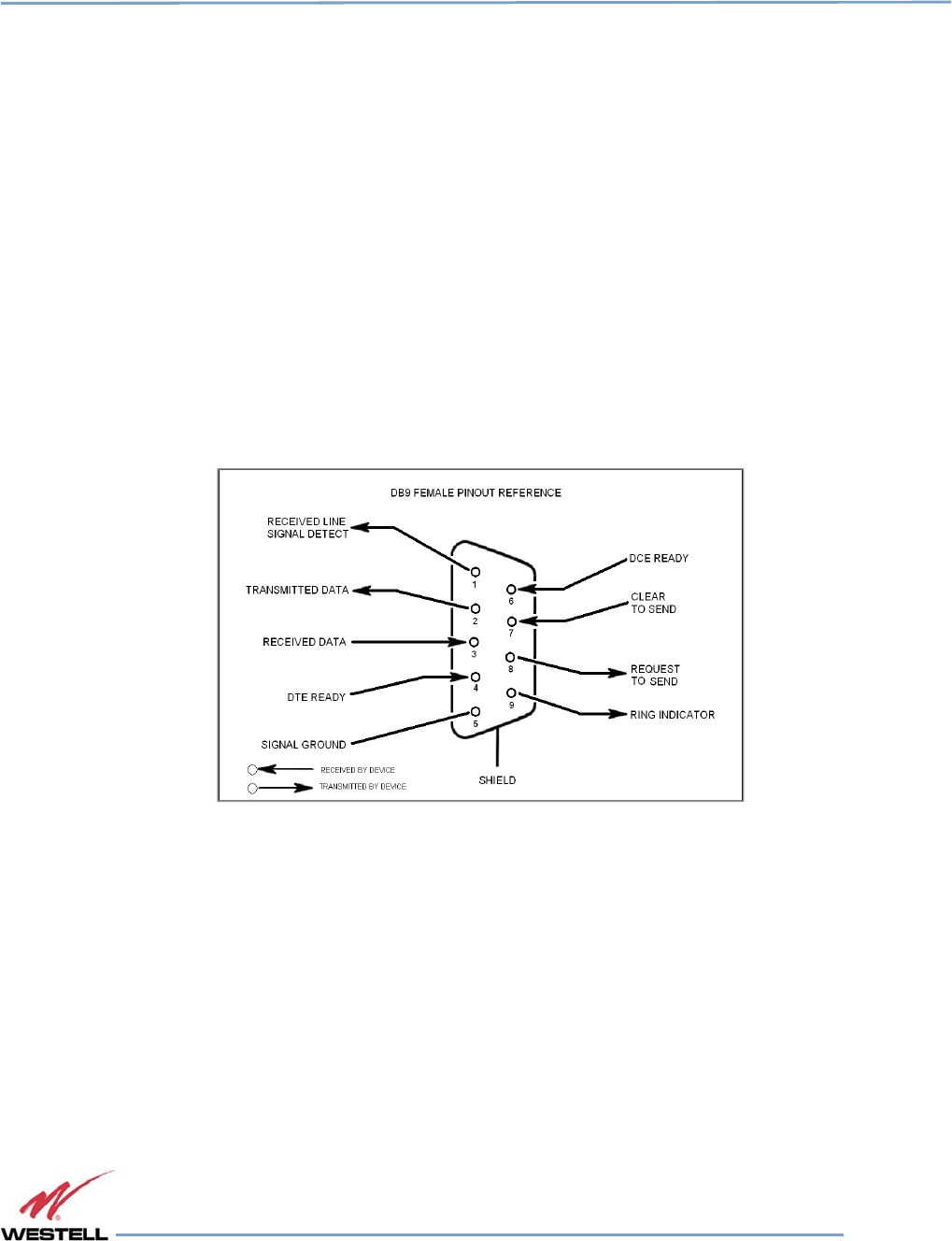
1.4 Local Communication Interface Ports
To allow monitoring and control, Westell repeaters are equipped with four ports that provide external communication
access: one ethernet, one DB-9 serial, and two USB ports. The ethernet port is a primary communications port to the
PC. The serial interface provides communications to a local PC. The USB interface provides a means to download
files from a memory device. The DB-9 pin assignments conform to the standard Electronic Industries Association
(EIA232) specification. A diagram of the pin descriptions is shown in Figure 1-1.
Figure
Figure Figure
Figure 1
11
1-
--
-1
11
1:
::
:
DB
DBDB
DB-
--
-9 Pin Descriptions
9 Pin Descriptions9 Pin Descriptions
9 Pin Descriptions
Connecting a serial cable to the COM port and using a terminal emulation program with a PC will allow
communication to the control processor’s Text Menu Interface (TMI).
1.5 EIA232 Pin Specifications
The connection diagram shown in Figure 1-1 is for reference only. It is intended as a resource for pinout information
if it is necessary to adapt your serial cable because of an unusual connector configuration. In the majority of cases,
this information is not needed.
1.6 USB Interface
This port is used for software updates and filter file uploads.

Digital Repeater Line
DSP85 Series
WESTELL.COM
© 2016 Westell Technologies 14 June 2016 Doc. No. 960-1666-MNL rJ
1.877.844.4274 Page 16 of 77
1.7 Ethernet
This port is used to provide local or remote access to the GUI.
1.8 Monitoring and Alarms
The DSP85 Series can be monitored via an ethernet connection using SNMP, SSH and/or HTTP protocols. Public
safety DSP models have dry contacts for traditional alarm panel monitoring as well.
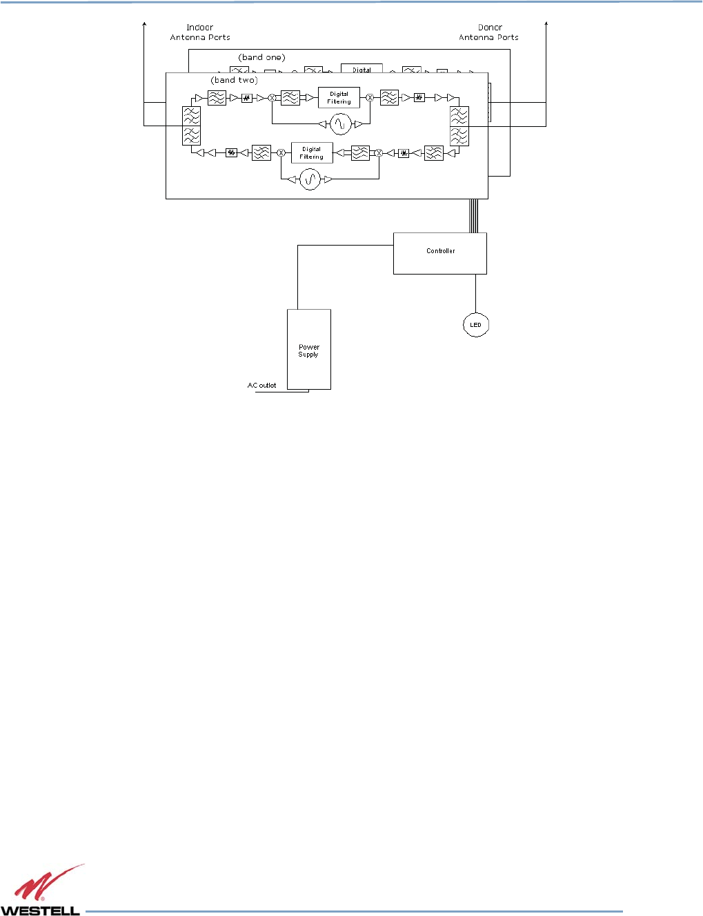
1.9 Circuit Operational Description
The repeater uses a single down-conversion/up-conversion scheme. There are multiple RF amplifier stages before
each down-converting mixer. The down-converting mixers are followed by a single IF amplifier. A digital signal
processor block processes the resultant digitized IF signal generated by an analog-to-digital converter. The filtered
digital signal is fed to a digital-to-analog converter and then up-converted to RF. A driver amplifier and power
amplifier make up the final gain stages before application to the diplexer. The maximum total system gain (diplexer
input to diplexer output) is nominally 85 dB for either the downlink or the uplink paths, with both links having
independent manual and Automatic Gain Controls (AGC).
AGC reacts to analog power detection on both the input and output of the uplink and downlink RF chains. A control
algorithm continuously monitors these detected values and dynamically adjusts various gain stages. The net system
gain value, entered manually, is optimally maintained without exceeding FCC parameters or overdriving the A/D
converters.
The Status or Power/Fault LED provides immediate visual indication of the unit’s primary power alarm status. The
repeater features automatic shutdown protection as a safety measure if excessive drive is applied to the input or an
oscillation condition occurs. When in a protected mode, a control algorithm determines the appropriate method of
recovery to a normal, previously defined state, or maintains the protection until it is manually reset. If recovery is
established, the LED is illuminated green or available to be reset. Events that trigger errors are saved in the event log.
1.10 Functional Block Diagrams
Digital Repeater Line
DSP85 Series
WESTELL.COM
© 2016 Westell Technologies 14 June 2016 Doc. No. 960-1666-MNL rJ
1.877.844.4274 Page 17 of 77
Figure
Figure Figure
Figure 1
11
1-
--
-2
22
2:
: :
: Dual Band Functional Block Diagram
Dual Band Functional Block DiagramDual Band Functional Block Diagram
Dual Band Functional Block Diagram
Digital Repeater Line
DSP85 Series
WESTELL.COM
© 2016 Westell Technologies 14 June 2016 Doc. No. 960-1666-MNL rJ
1.877.844.4274 Page 18 of 77
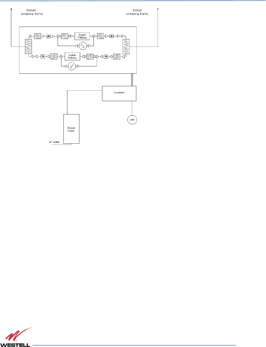
Figure 1-3: Single Band Functional Block
Diagram

Digital Repeater Line
DSP85 Series
WESTELL.COM
© 2016 Westell Technologies 14 June 2016 Doc. No. 960-1666-MNL rJ
1.877.844.4274 Page 19 of 77
2
Optimizing the System during Installation
2.1 System Setup Considerations
Check all cables for shorts and opens. Verify that there are no cables with loose or poor connections. RF leakage
could cause oscillation to occur under some conditions.
Check the rooftop antenna (donor antenna), if directional, for proper alignment along the calculated compass
heading. Typically, the directional antenna is aimed at the same site that your handset uses, but it may not always
be. It is critical that the installer contact the service provider for information about, and approval of, the selected cell
site before the system is activated.
IMPORTANT
The installation height of the antenna for AWS band (1700/2100 MHz) operations is
limited to 10 meters above ground for compliance with Section 27.50.
If cables and alignment are acceptable and a problem persists, it may be necessary to use a spectrum analyzer to
examine the signal environment in which the repeater is operating. The existence of strong adjacent channel signals
within the frequency band(s) can cause the AGC to reduce the amplifier’s gain or cause alarms. In some cases,
additional filtering or attenuation may be required to reject these unwanted signals. In some instances, the donor
antenna can be repositioned horizontally, to place the interference source in an antenna pattern null. There also may
be some cases where the interference from outside signals is so great that they cannot be filtered, reduced or
eliminated without expensive (and possibly prohibitive) measures. In these cases, it may not be practical to use the
repeater for providing coverage to these sites.
2.2 Suggested Spectrum Analyzer Setting
When troubleshooting RF issues and surveying challenging RF environments, it is important to have a spectrum
analyzer that is capable of measuring the frequency you are using. Use an attenuator to protect the input when
connected to a source of RF power, such as a repeater or a powered DAS.
Measure both uplink and downlink.
Measure downlink on the donor cable and at the output (server) port of the powered repeater.
Measure uplink at the lead from the DAS (on fiber-powered DAS, where the lead would connect to the server port on
the repeater) and at the donor port with the repeater power on.
Measurements may also be necessary at server antenna locations. The spectrum analyzer must be equipped with a
whip antenna.
Set the resolution bandwidth (RBW) to 200 kHz for GSM and 1 MHz for CDMA. If you cannot select these values, use
the closest available values. Set the video filter to about one-tenth of RBW. Set other settings, such as span, to the
appropriate values. Ensure that there are no signals above the top of the screen.
If you cannot see an adjacent out-of-band signal when using the 1 MHz RBW filter, decrease the RBW to see the
close-in-frequency signals. Set the RBW back when you want to measure the power level.

Digital Repeater Line
DSP85 Series
WESTELL.COM
© 2016 Westell Technologies 14 June 2016 Doc. No. 960-1666-MNL rJ
1.877.844.4274 Page 20 of 77
2.3 Important Installation Notes
Inadequate isolation between the outside and inside antennas may cause regenerative feedback in the system. This
feedback can cause the amplifier to emit a continuous signal at maximum amplitude and, in some cases, interfere
with normal operation of the cell site. It is important to consider the layout and placement of the system carefully.
Refer to the Preface Safety Guidelines and Important Safety Information for proper antenna selection and
installation.
DANGER!
To avoid serious injury or death and repeater damage, do not install donor or server
antennas near overhead power lines or high power components. Allow enough
distance so that, if antennas fall, they will not contact those components.
WARNING!
Close proximity to the donor or server antennas with the repeater in operation may
expose the user or installer to RF fields that exceed FCC limits for human exposure.
CAUTION
Amplifier or handset damage may occur if a handset is connected directly to the
repeater or to the coax that leads to the repeater.
2.4 Installation Guidelines
2.4.1 Donor Antenna
• Accurately determine the azimuth to the donor cell site.
• Obtain the donor site information and approval from the service provider/carrier.
• Ensure that the radiation path to the donor cell site is as unobstructed as possible.
• Mount the donor antenna at or toward the edge of the roof, in the direction of the donor site. Try
to avoid having the RF signal from the donor pass above the location(s) of the service antennas.
Normally, service antennas are located behind and below the donor antenna (as viewed from above).
This approach will help avoid interference and feedback to and from the service antennas.
• Normally, mounting the donor antenna higher will allow a less obstructed path to the donor site.
However, in high traffic metro areas avoid mounting the donor antenna any higher than necessary
as the quality of the donor signal may start to become less stable and it is more likely to encounter
adjacent channel interference.
• When possible, shield the donor antenna’s rear by locating it so that HVAC units and/or penthouse
structures are behind the antenna, relative to the donor cell site location.
• Ground system components in accordance with NEC 810-15, 21 as required.

Digital Repeater Line
DSP85 Series
WESTELL.COM
© 2016 Westell Technologies 14 June 2016 Doc. No. 960-1666-MNL rJ
1.877.844.4274 Page 21 of 77
2.4.2 Antennas
• Use omnidirectional antennas indoors, and locate them centrally with respect to the intended
coverage area to minimize signal leakage to the outside. Use directional antennas indoors only in
special cases when higher gain and directionality would be helpful and RF exposure limits will not be
exceeded.
• To avoid repeater uplink overload and gain limiting, mount the indoor antennas away from areas
where mobile subscribers frequently use their phones such as desks or dispatch areas.
• To determine the quantity and locations of indoor antennas, use an appropriate phone’s signal meter
to determine areas of weak signals. These are the approximate areas where indoor antennas may be
needed. Be aware the signal from an indoor antenna, in most cases, can be expected to penetrate
about two standard office sheetrock-type walls to reach users. After two walls, or if the walls are
made of other materials, it may be necessary to split the available signal and add more antennas.
2.5 Optional Accessories
A complete line of accessories is available from Westell. Check with your Westell distributor for any additional items
needed. Below are just a few examples suitable for most in-building needs:
2.5.1 Outside Donor Antenna
• PCS - model number CSI-AY/1.85-1.99/10
• Cellular - model number CSI-AY/806-960/14
2.5.2 Inside Omnidirectional Antenna
• Quad-band - model number ClearLink-O/698-2.7K/N
2.5.3 Power Dividers
• 2:1 - model number ClearLink -SPD2/698-2.7K-LP/N
• 3:1 - model number ClearLink -SPD3/698-2.7K-LP/N
• 4:1 - model number ClearLink -SPD4/698-2.7K-LP/N
2.5.4 Grounding Kit
• Model number CSI-GKIT

Digital Repeater Line
DSP85 Series
WESTELL.COM
© 2016 Westell Technologies 14 June 2016 Doc. No. 960-1666-MNL rJ
1.877.844.4274 Page 22 of 77
2.5.5 Directional Couplers
• 6 dB - model number ClearLink-DC6/698-2.7K/N
• 10 dB - model number ClearLink -DC10/698-2.7K/N
• 15 dB - model number ClearLink -DC15/698-2.7K/N
• 20 dB - model number ClearLink -DC20/698-2.7K/N
• 30 dB - model number ClearLink -DC30/698-2.7K/N
2.5.6 19” Rack Shelf
• Model number CSI-RMS-250
2.5.7 UPS
• Battery backup, two hour single-band, one hour dual-band - model number CS48-985-600
• Battery backup, four hour single-band, two hour dual-band - model number CS48-985-601
2.5.8 Cross Band Couplers
• Quad-band Rack Mount - model number CSI-CM250-7/C/AW/P (700 LTE, Cellular, PCS and AWS)
• Quad-band Wall Mount - model number CSI-CBC/QUAD/N (700 LTE, Cellular, PCS and ASW)
• Tri-band Rack Mount - model number CSI-CM250-U7C/C/P (700 Upper C LTE, Cellular and PCS)
• Tri-band Wall Mount - model number CSI-CBC21/740-1990/N (700 Upper C LTE, Cellular and PCS)
• Tri-band Rack Mount - model number CSI-CM250-L7/C/P (700 Lower A/B/C LTE, Cellular and PCS)
• Tri-band Wall Mount - model number CSI-CBC21/696-1990/N (700 Lower A/B/C LTE, Cellular and
PCS)
Digital Repeater Line
DSP85 Series
WESTELL.COM
© 2016 Westell Technologies 14 June 2016 Doc. No. 960-1666-MNL rJ
1.877.844.4274 Page 23 of 77
3
Web-based GUI
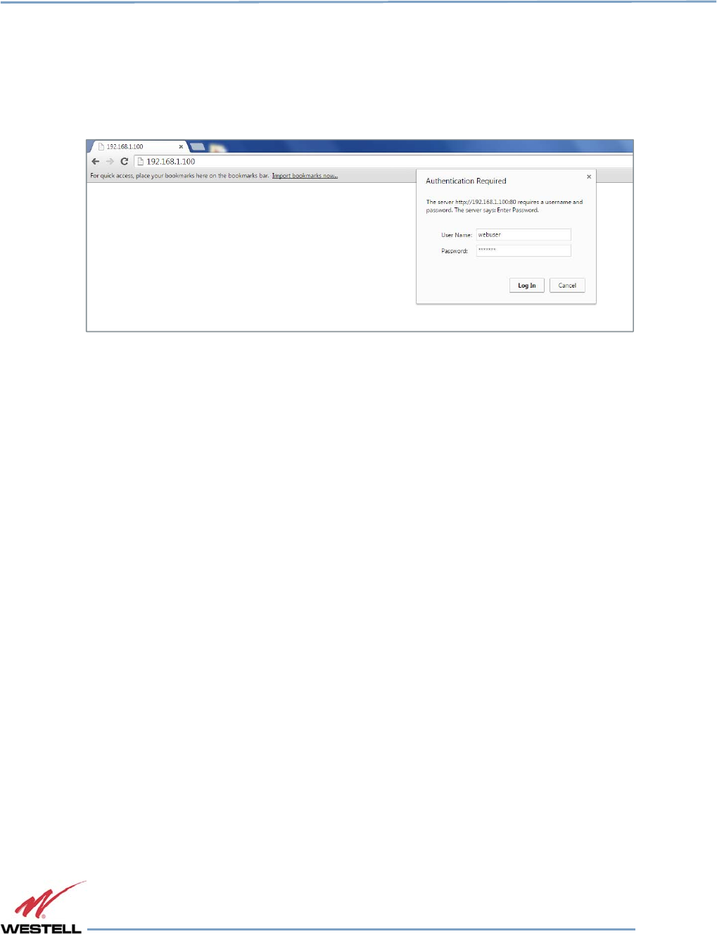
3.1 Web-based GUI Session
You may access the repeater using a LAN connection and a web browser program such as Internet Explorer, Figure
3-1.
Figure
Figure Figure
Figure 3
33
3-
--
-1
11
1: User Connection Login
: User Connection Login: User Connection Login
: User Connection Login
The repeater ships with the default IP address of 192.168.1.100, but you can change it later if you need to.
1. If connecting directly to the repeater from a laptop or PC with a crossover CAT-5e cable or over a
LAN, enter the IP address of the repeater into the browser address line to connect.
2. Most users will need to update the TCP/IP settings on their computer to enable connection to a host
that has a static IP. Refer to section 4.4 Additional Tips for more information.
a. Select Use the following IP Address and enter the IP address as follows: 192.168.1.x, where
‘x’ is any number from 2 to 254, inclusive, except 100. The subnet mask is 255.255.255.0.
Refer questions pertaining to these settings to your IT department, or review section 4.4
Additional Tips.
3. When connection is made, you will be prompted for a user name and password. For the purpose of
the GUI session, enter the default user name webuser and the password is csi1234, shown in Figure
3-1. Username and password can be changed as required.
Internet access is not required to use the GUI. If you are connecting using a laptop, verify that your ethernet port has
power. Some laptops will not allow ethernet connection when on battery power. If this occurs, connect to AC line
power or update the power settings.
NOTE
The GUI screens shown throughout this manual show a dual-band Cell/PCS
configuration. They are for illustration purposes only. The actual screen you see will
depend on the individual configuration.
Digital Repeater Line
DSP85 Series
WESTELL.COM
© 2016 Westell Technologies 14 June 2016 Doc. No. 960-1666-MNL rJ
1.877.844.4274 Page 24 of 77
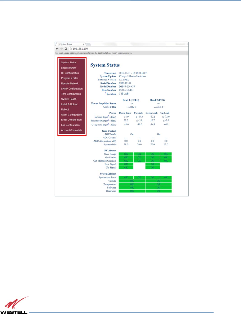
3.2 System Status
After login, the System Status page displays, Figure 3-2. The Navigation Menu on the left side of the page
(highlighted in Figure 3-2) shows available operations. Clicking a menu item displays the page for that operation.
Figure
Figure Figure
Figure 3
33
3-
--
-2
22
2: System Status
: System Status: System Status
: System Status
Digital Repeater Line
DSP85 Series
WESTELL.COM
© 2016 Westell Technologies 14 June 2016 Doc. No. 960-1666-MNL rJ
1.877.844.4274 Page 25 of 77
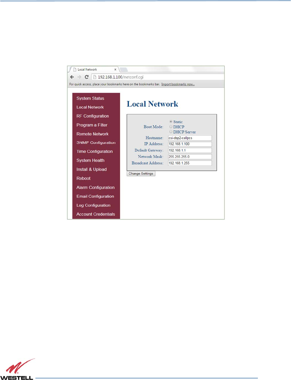
3.3 Local Network
Click Local Network in the System Status left page menu to display the Local Network screen, Figure 3-3, displays.
This page allows you to modify the network configuration. The default Boot Mode is Static. Check with your IT
department for explanation and approval of the DHCP and DHCP server options you plan to use before you select
them.
Figure
Figure Figure
Figure 3
33
3-
--
-3
33
3: Local Network
: Local Network: Local Network
: Local Network
NOTE
In repeaters with software version 2.2.4 or older, only letters, numbers and
underscores are acceptable in the text fields. In repeaters with software version 2.3.0
and newer, underscores are unacceptable. Hyphens are acceptable.
After you have made the necessary changes, refresh the page to review the fields and ensure the information is correct.
NOTE
Changing network settings causes the current TCP/IP connection to fail because
changes take effect immediately.
Digital Repeater Line
DSP85 Series
WESTELL.COM
© 2016 Westell Technologies 14 June 2016 Doc. No. 960-1666-MNL rJ
1.877.844.4274 Page 26 of 77
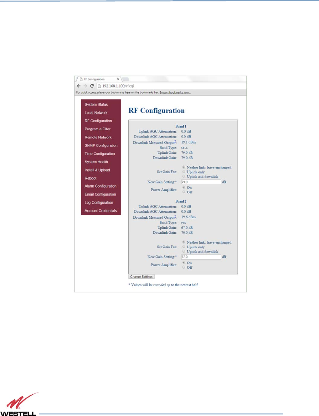
3.4 RF Configuration
Click RF Configuration in the left page to display and modify the RF Configuration page, Figure 3-4.
To change gain settings, select the Uplink only or Uplink and downlink radio buttons. Enter the desired gain value
between 53.5 dB and 85 dB. The repeater will not allow values outside this range. Implement change in gain by
clicking the Change Settings button at the bottom of the page.
Figure
Figure Figure
Figure 3
33
3-
--
-4
44
4: RF Configuration
: RF Configuration: RF Configuration
: RF Configuration
Digital Repeater Line
DSP85 Series
WESTELL.COM
© 2016 Westell Technologies 14 June 2016 Doc. No. 960-1666-MNL rJ
1.877.844.4274 Page 27 of 77
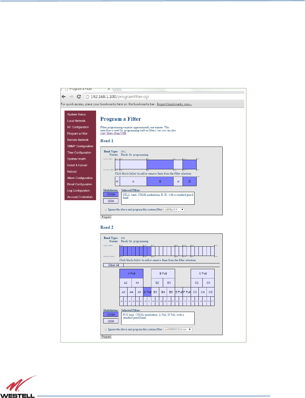
3.5 Program a Filter
Click Program a Filter in the left page menu. The Program a Filter page, Figure 3-5, displays. Change the selected
filter in the band/sub-band and modulation options.
Deselect undesired bands/sub-bands if they are selected (highlighted). The Clear All button on the selected band
deselects all band and sub-bands simultaneously. Clicking the Program button completes the selection and loads
the desired filter. This process may take several minutes. If the desired filter is not currently in the repeater, additional
filters, along with instructions on how to load them, are available by contacting Westell Technologies.
Figure 3-5: Program a Filter
Digital Repeater Line
DSP85 Series
WESTELL.COM
© 2016 Westell Technologies 14 June 2016 Doc. No. 960-1666-MNL rJ
1.877.844.4274 Page 28 of 77
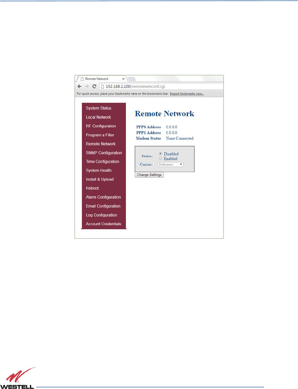
3.6 Remote Network
If the repeater includes a USB modem kit, click Remote Network in the left page menu. The Remote Network page
displays, Figure 3-6. Highlight the carrier on whose network the repeater and modem will be configured and click
the Change Settings button. Refer to the documentation included with the modem kit for additional information
about modem configuration. If the repeater is connected to an ethernet device for remote access and/or monitoring,
this feature must be disabled.
Figure
Figure Figure
Figure 3
33
3-
--
-6
66
6: Remote Network
: Remote Network: Remote Network
: Remote Network
Digital Repeater Line
DSP85 Series
WESTELL.COM
© 2016 Westell Technologies 14 June 2016 Doc. No. 960-1666-MNL rJ
1.877.844.4274 Page 29 of 77
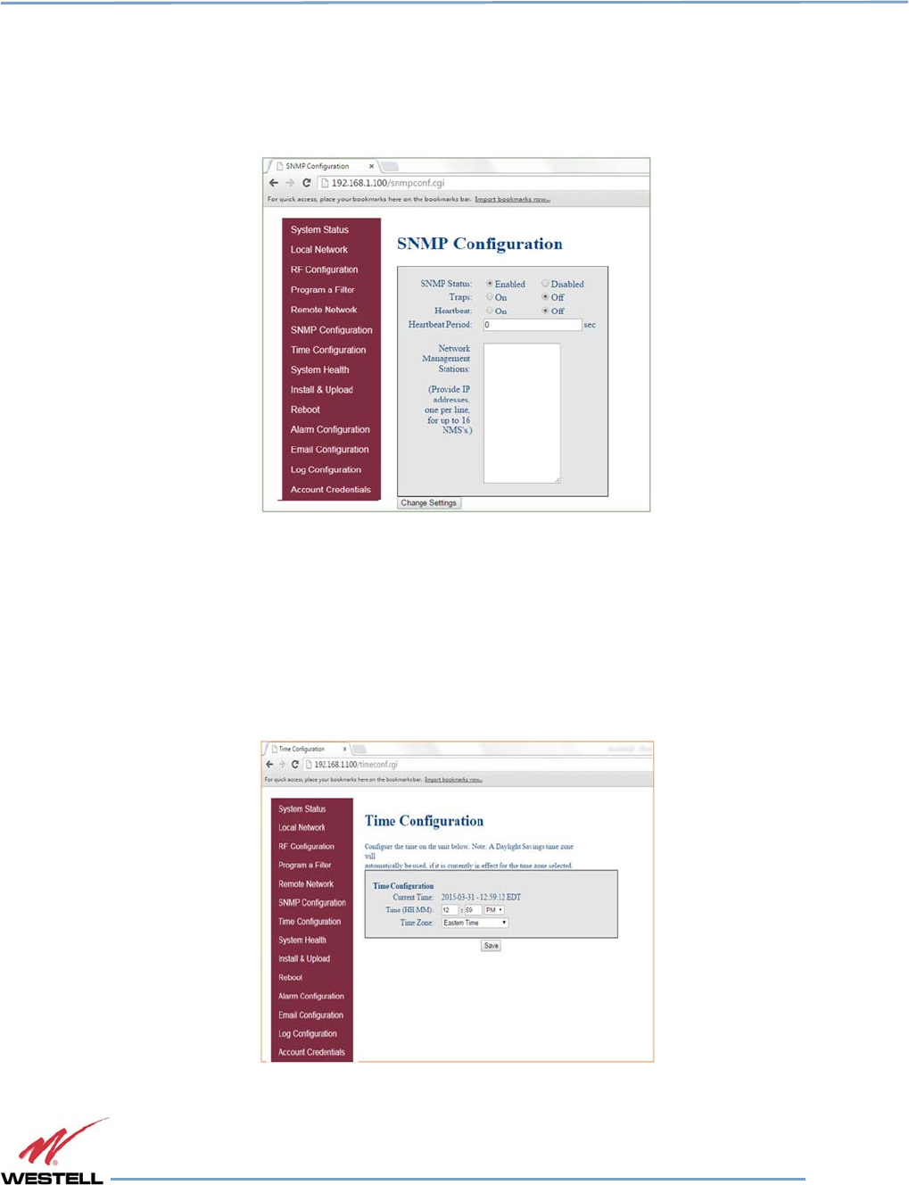
3.7 SNMP Configuration
To change SNMP settings, click SNMP Configuration in the left page menu. The SNMP Configuration page, Figure
3-7, displays. Check with an IT professional for proper SNMP setting requirements.
Figure
Figure Figure
Figure 3
33
3-
--
-7
77
7: SNMP Configuration
: SNMP Configuration: SNMP Configuration
: SNMP Configuration
3.8 Time Configuration
Click Time Configuration in the left page menu to display the Time Configuration page, Figure 3-8. This page
allows you to set the current system time and time zone.
Figure
Figure Figure
Figure 3
33
3-
--
-8
88
8: Time Configuration
: Time Configuration: Time Configuration
: Time Configuration
Digital Repeater Line
DSP85 Series
WESTELL.COM
© 2016 Westell Technologies 14 June 2016 Doc. No. 960-1666-MNL rJ
1.877.844.4274 Page 30 of 77
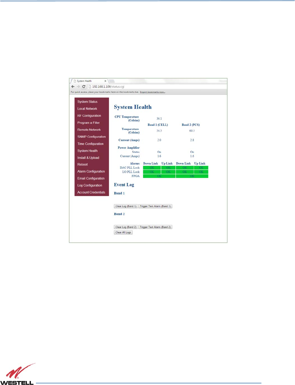
3.9 System Health
Click System Health in the left page menu to display the System Health page, Figure 3-9. This page displays the
current repeater status. Click the Clear Log button to clear LED indicators, alarms and the event log. If required,
display the System Health screen, click Trigger Test Alarm and wait for confirmation that the WSP representative
that is responsible for monitoring the repeater has been notified of the alarm.
Be sure to click Clear All Logs before logging out of the Web interface.
Figure
Figure Figure
Figure 3
33
3-
--
-9
99
9: System Health
: System Health: System Health
: System Health
Digital Repeater Line
DSP85 Series
WESTELL.COM
© 2016 Westell Technologies 14 June 2016 Doc. No. 960-1666-MNL rJ
1.877.844.4274 Page 31 of 77
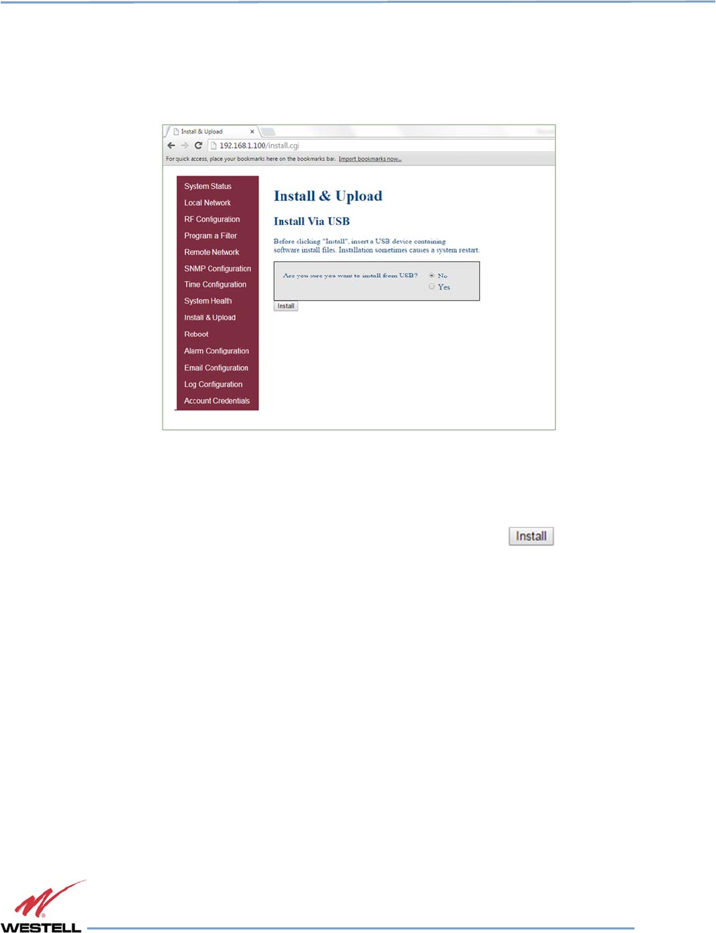
3.10 Install and Upload
Click Install & Upload in the left page menu to display the Install & Upload page, Figure 3-10. Use this page to
perform a software installation or upgrade. Contact Westell Technologies for new software versions.
Figure
Figure Figure
Figure 3
33
3-
--
-10
1010
10: Install & Upload
: Install & Upload: Install & Upload
: Install & Upload
IMPORTANT
You must click to select the Yes radio button before you click the button.
If you do not, the installation will not be performed and an error message will
display.
Digital Repeater Line
DSP85 Series
WESTELL.COM
© 2016 Westell Technologies 14 June 2016 Doc. No. 960-1666-MNL rJ
1.877.844.4274 Page 32 of 77
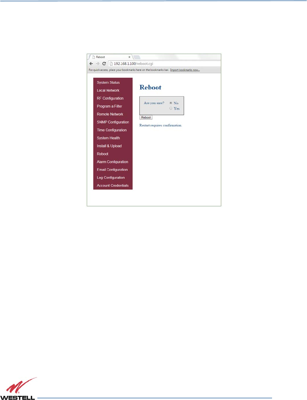
3.11 Reboot
Click Reboot in the left menu to display the Reboot page, Figure 3-11, which allows you to reboot the repeater. A
reboot takes approximately three to five minutes to complete.
Figure
Figure Figure
Figure 3
33
3-
--
-11
1111
11: Reboot
: Reboot: Reboot
: Reboot
Digital Repeater Line
DSP85 Series
WESTELL.COM
© 2016 Westell Technologies 14 June 2016 Doc. No. 960-1666-MNL rJ
1.877.844.4274 Page 33 of 77
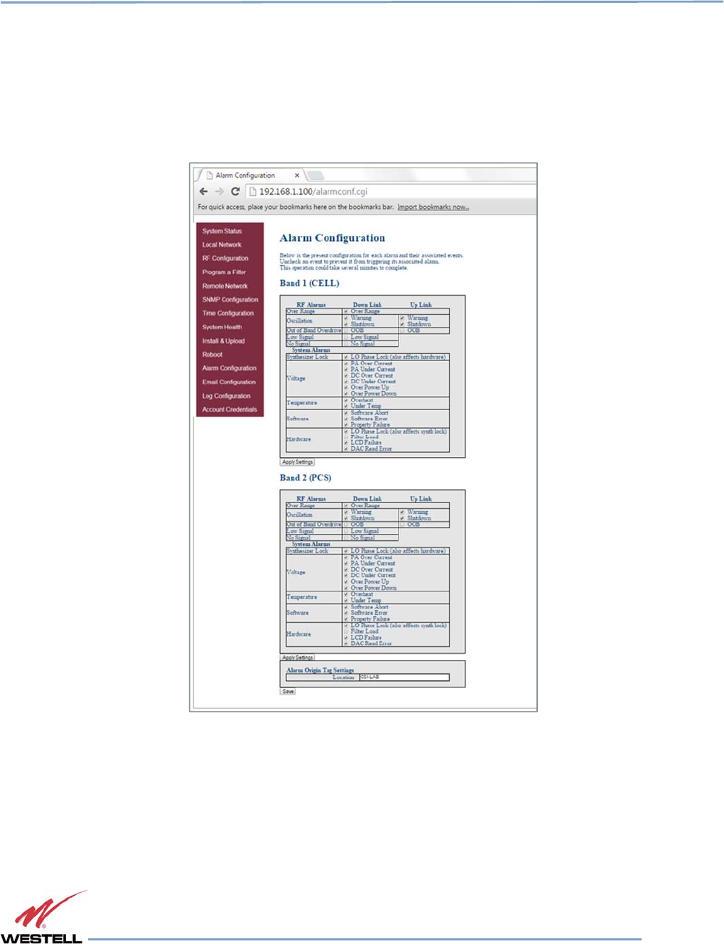
3.12 Alarm Configuration
Click Alarm Configuration in the left page menu to display the Alarm Configuration page, Figure 3-12. This page
displays the current alarm configurations for each band and allows you to make changes by editing alarm settings
and the clicking the Apply Settings button. Letters, numbers and hyphens are the only acceptable nomenclature for
the location field. Hyphens may not be used as the first or last character.
Figure 3-12: Alarm Configuration
Digital Repeater Line
DSP85 Series
WESTELL.COM
© 2016 Westell Technologies 14 June 2016 Doc. No. 960-1666-MNL rJ
1.877.844.4274 Page 34 of 77
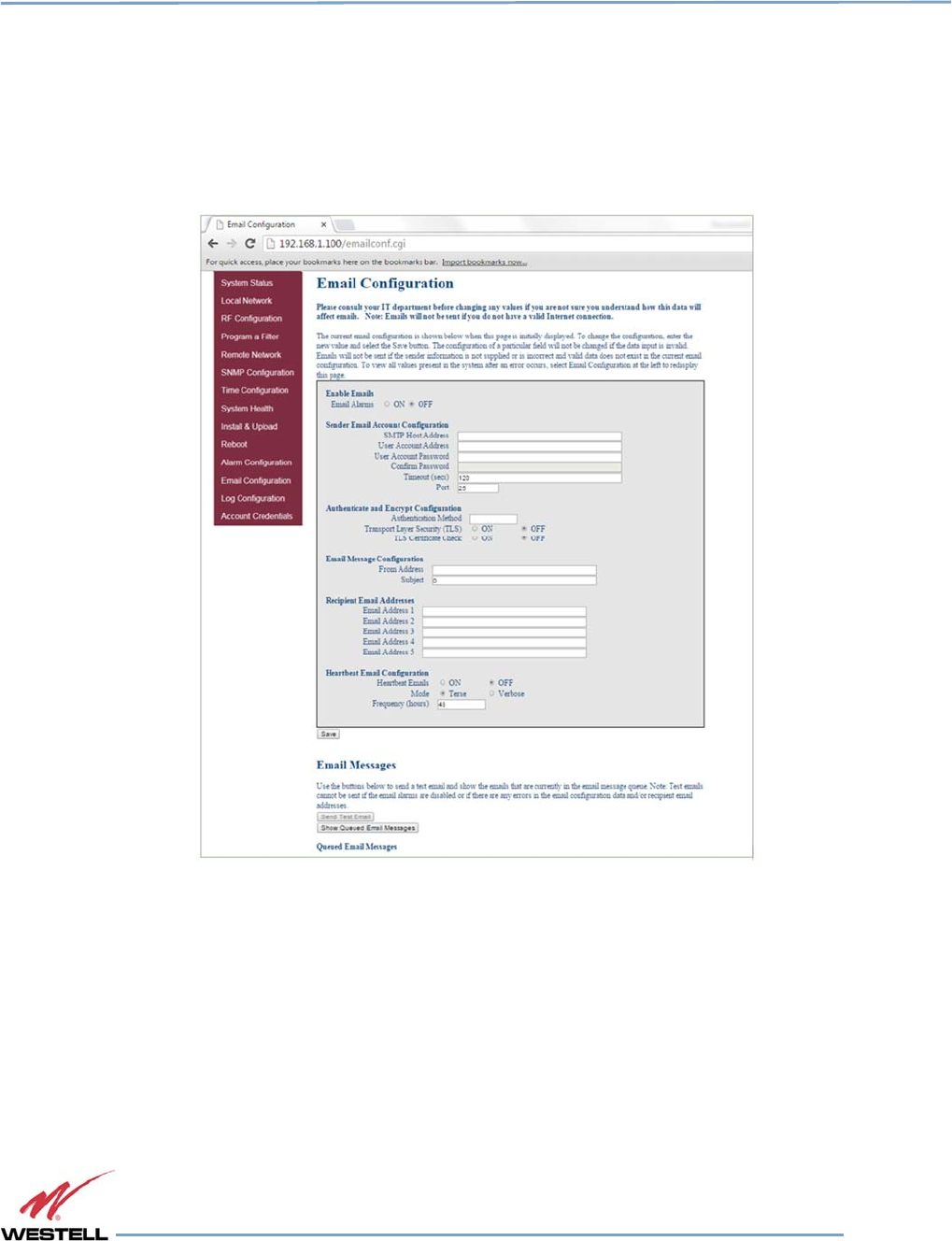
3.13 Email Configuration
Clicking Email Configuration in the left page menu displays the Email Configuration page, Figure 3-13. This page
allows you to enter up to five e-mail addresses to which the repeater can send specified alarm messages. Alarm
messages can be sent only when the repeater is connected via ethernet or wireless modem, and e-mail alarm
notification or remote networking are enabled. The software will not allow you to enter invalid characters in any field.
Figure
Figure Figure
Figure 3
33
3-
--
-13
1313
13: Email Configuration
: Email Configuration: Email Configuration
: Email Configuration
Digital Repeater Line
DSP85 Series
WESTELL.COM
© 2016 Westell Technologies 14 June 2016 Doc. No. 960-1666-MNL rJ
1.877.844.4274 Page 35 of 77
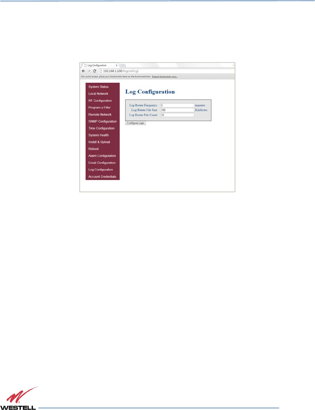
3.14 Log Configuration
Click Log Configuration to display the Log Configuration page, Figure 3-14. This page provides you with the ability
to change three aspects of the way log files are created and stored: Log Rotate Frequency, Log Rotate File Size and
Log Rotate File Count. Enter the desired settings for each and click the Configure Logs button to save the settings.
Figure
Figure Figure
Figure 3
33
3-
--
-14
1414
14: Log Configuration
: Log Configuration: Log Configuration
: Log Configuration
Digital Repeater Line
DSP85 Series
WESTELL.COM
© 2016 Westell Technologies 14 June 2016 Doc. No. 960-1666-MNL rJ
1.877.844.4274 Page 36 of 77
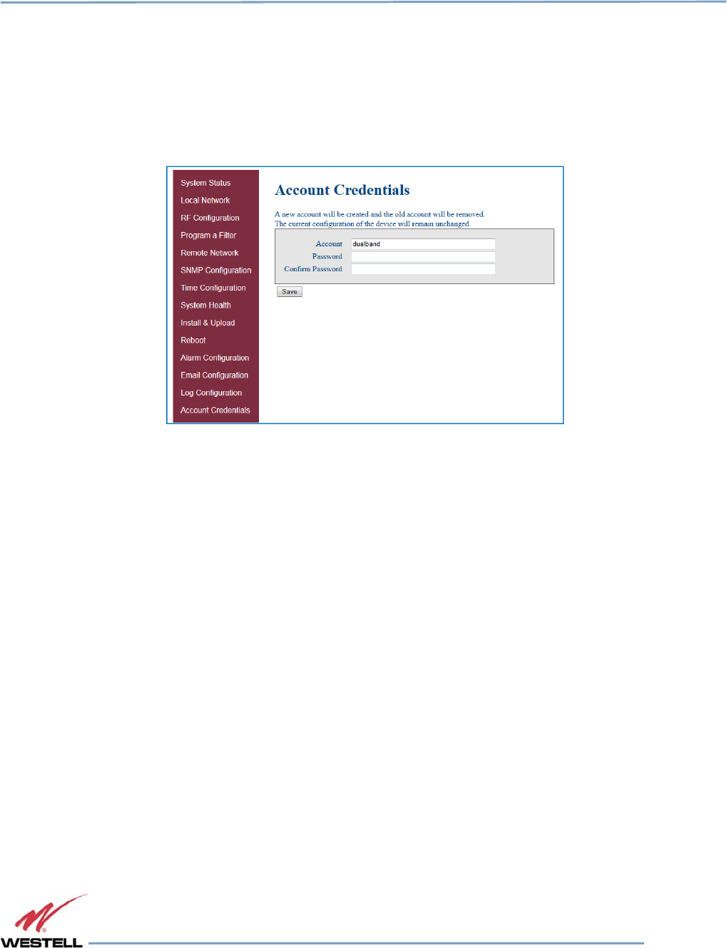
3.15 Account Credentials
Clicking Account Credentials in the left page menu displays the Account Credentials page, Figure 3-15. On this page,
you can create a new account or reset the repeater password. The old account is removed when the new account is
created. If you need to recover a password you have set, contact Westell Technologies technical support line at
1.877.844.4274, Option 2, then Option 1 for assistance.
Figure
Figure Figure
Figure 3
33
3-
--
-15
1515
15:
: :
: Account Credentials
Account CredentialsAccount Credentials
Account Credentials
Digital Repeater Line
DSP85 Series
WESTELL.COM
© 2016 Westell Technologies 14 June 2016 Doc. No. 960-1666-MNL rJ
1.877.844.4274 Page 37 of 77
4
Console Interface
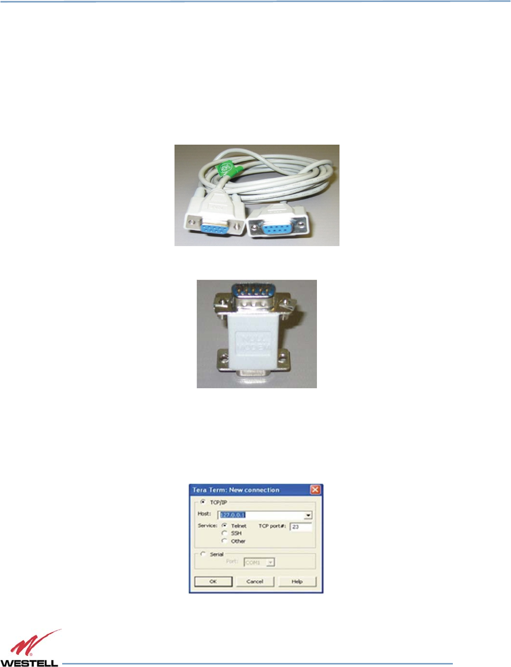
4.1 Text Menu Interface (Local Access)
To gain local access to the repeater TMI, also known as the console
interface,
connect a null modem serial cable as
shown in Figure 4-1, from the serial
connector
of the laptop to the serial port on the repeater. This connector is labeled
COM. In some cases, if the gender of the
connector
is not the same as the connectors shown in Figure 4-1, a
gender adapter
(optional)
, Figure 4-2
may
also be required.
Figure
Figure Figure
Figure 4
44
4-
--
-1
11
1: Null Modem Cable
: Null Modem Cable: Null Modem Cable
: Null Modem Cable
Figure
Figure Figure
Figure 4
44
4-
--
-2
22
2: Gender Adapter
: Gender Adapter: Gender Adapter
: Gender Adapter
Many terminal emulation programs will work if properly configured. In this section, Tera Term is used to establish
the TMI session.
Figure 4-3 displays when the application opens.
Figure
Figure Figure
Figure 4
44
4-
--
-3
33
3: Ter
: Ter: Ter
: Tera
aa
a
Term Pro Web Start Up
Term Pro Web Start UpTerm Pro Web Start Up
Term Pro Web Start Up
Digital Repeater Line
DSP85 Series
WESTELL.COM
© 2016 Westell Technologies 14 June 2016 Doc. No. 960-1666-MNL rJ
1.877.844.4274 Page 38 of 77
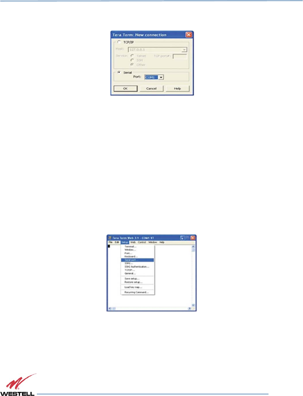
1. Select the Serial radio button and click OK, Figure 4-4.
Figure
Figure Figure
Figure 4
44
4-
--
-4
44
4: Serial Radio Button
: Serial Radio Button: Serial Radio Button
: Serial Radio Button
NOTE
It may be necessary, to determine which COM port your computer uses for the
communications port. Do this in by viewing the system properties section of the
control panel using device manager. In this case, the communications port is COM
1. This is not to be confused with the serial port on the bottom panel of the repeater
that is also labeled COM 1.
2. Click OK. A blank dialog screen, Figure 4-5 displays.
3. Click Setup to expand the drop-down menu, Figure 4-5 and select Serial port. The Serial Port Setup
window, Figure 4-6, displays. In this window, you can make changes to the serial port setup.
Figure
Figure Figure
Figure 4
44
4-
--
-5
55
5: Setup
: Setup: Setup
: Setup
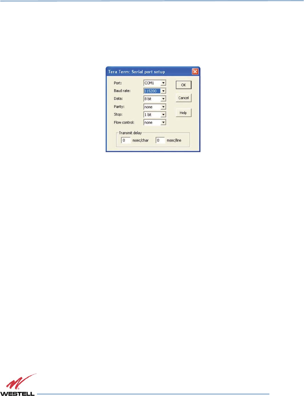
Digital Repeater Line
DSP85 Series
WESTELL.COM
© 2016 Westell Technologies 14 June 2016 Doc. No. 960-1666-MNL rJ
1.877.844.4274 Page 39 of 77
4. Configure the terminal program for the correct COM port, Figure 4-6.
a. Under the Port drop-down list, select COM 1.
b. Under the Baud rate drop-down list, select 115200.
Figure
Figure Figure
Figure 4
44
4-
--
-6
66
6: Serial Port Setup
: Serial Port Setup: Serial Port Setup
: Serial Port Setup
5. After completing the serial port changes, click OK. A dialog displays, prompting you to enter a user
name and password.
6. Enter a username and password and press the Enter key. The TMI Main Menu displays, Figure 4-7.
IMPORTANT
In dual-band units, each band is changed independently and requires an
independent login. The default user name for the first band is bandone. The default
user name for the second band is bandtwo.
The password for both bands is csi1234.
7. The set parameters option is disabled by default. To enable it, press 1. A dialog displays, prompting
you to enter a user name and password.
8. Enter the default user name csi and the password csi1234.
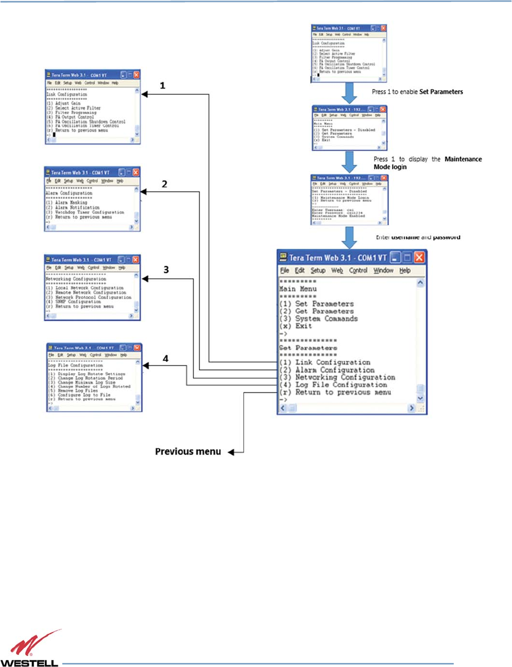
Digital Repeater Line
DSP85 Series
WESTELL.COM
© 2016 Westell Technologies 14 June 2016 Doc. No. 960-1666-MNL rJ
1.877.844.4274 Page 40 of 77
Figure
Figure Figure
Figure 4
44
4-
--
-7
77
7: TMI
: TMI : TMI
: TMI Menu
MenuMenu
Menus
ss
s
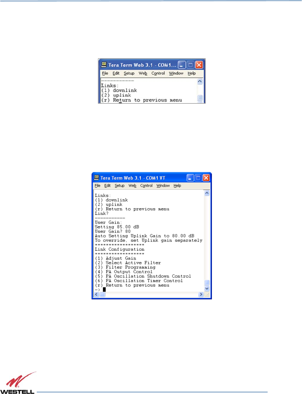
Digital Repeater Line
DSP85 Series
WESTELL.COM
© 2016 Westell Technologies 14 June 2016 Doc. No. 960-1666-MNL rJ
1.877.844.4274 Page 41 of 77
When you select an item in the Set Parameter menu, a sub-menu expands to allow configuration of the selected
parameter.
For example, Selecting 1 - Adjust Gain in the Link Configuration menu, displays the Links: menu shown in Figure
4-8.
Figure
Figure Figure
Figure 4
44
4-
--
-8
88
8: Adjust Gain
: Adjust Gain: Adjust Gain
: Adjust Gain
Selecting option (1) downlink in the Links: menu displays the current user gain, Figure 4-9.
Change the gain value by entering the desired gain value at the prompt. You may return to the previous menu by
selecting r.
Figure
Figure Figure
Figure 4
44
4-
--
-9
99
9: U
: U: U
: User Gain
ser Gainser Gain
ser Gain
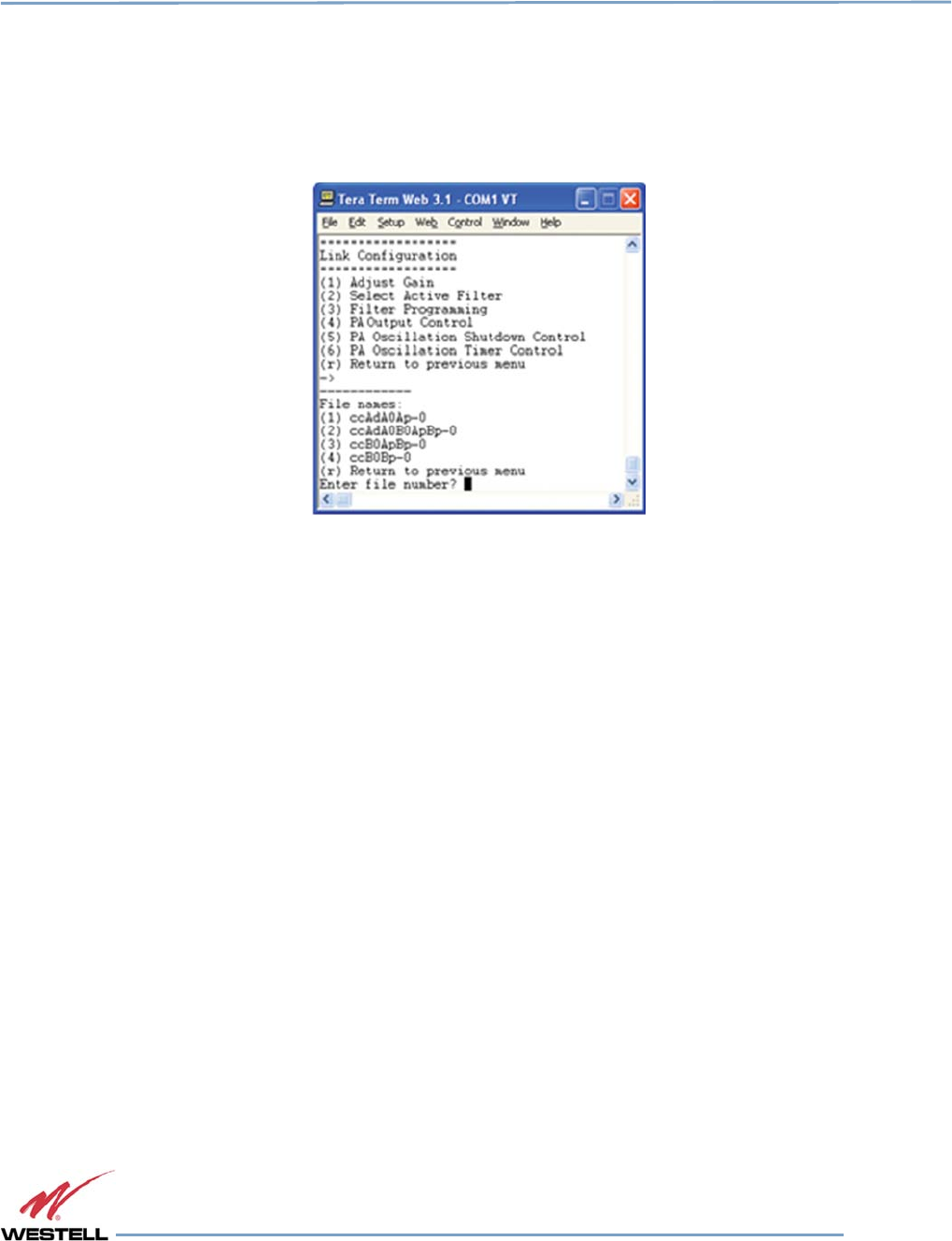
Digital Repeater Line
DSP85 Series
WESTELL.COM
© 2016 Westell Technologies 14 June 2016 Doc. No. 960-1666-MNL rJ
1.877.844.4274 Page 42 of 77
All other sub-menu items function in much the same way as the Adjust Gain item. Some of the items will offer
additional selections and will be self-explanatory. Figure 4-10 is one example of these additional options. This menu
displays when (3) Filter Programming is selected.
Figure
Figure Figure
Figure 4
44
4-
--
-10
1010
10: Selecting Filter
: Selecting Filter : Selecting Filter
: Selecting Filter Programs
ProgramsPrograms
Programs
IMPORTANT
Navigate to File>Disconnect to terminate a session. If you do not, the port may
become disabled and the system will need to be rebooted.
4.2 Telnet Session (Remote Access)
You may access the repeater using a LAN connection and a terminal emulation program for TCP/IP. As with the serial
connection, many terminal emulation programs will work, if properly configured.
In the following section, Tera Term is used to establish the Telnet session. The network configuration of the computer
and the repeater that is being controlled must be set up with the same subnet and subnet mask to establish a link.
In other words, the IP addresses of both the computer and the repeater must use the same group of IP address
number sets.
For example, the repeater ships with a default IP address of 192.168.1.100 and a subnet mask of 255.255.255.0, as
shown in Figure 4-11. To connect, the computer used for the link would normally need an IP address of, for example,
192.168.1.2 with a subnet mask of 255.255.255.0, the same subnet mask as the repeater.
In this example, the last digit of the IP address may be any number except 1,100 and 255. Configuring your PC is
straight forward, but it varies according to the operating system used. If you require assistance, contact your IT
department or you may review the 4.4 Additional Tips section.
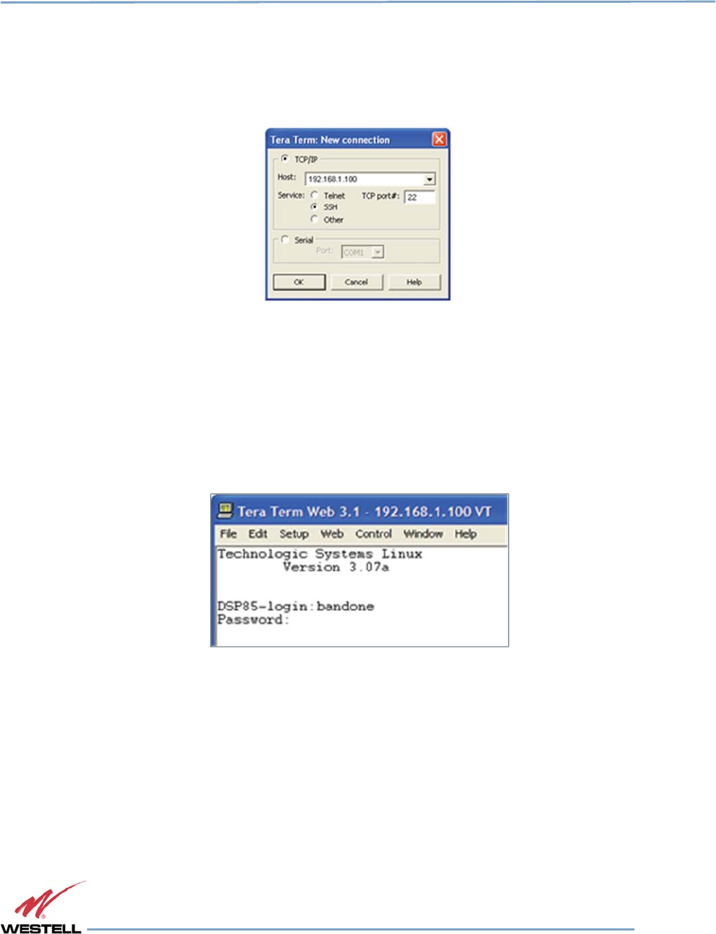
Digital Repeater Line
DSP85 Series
WESTELL.COM
© 2016 Westell Technologies 14 June 2016 Doc. No. 960-1666-MNL rJ
1.877.844.4274 Page 43 of 77
When the Tera Term application opens, the window in Figure 4-11 displays.
Figure
Figure Figure
Figure 4
44
4-
--
-11
1111
11: Def
: Def: Def
: Default IP Address
ault IP Addressault IP Address
ault IP Address
1. Change the default host IP address to the IP address of the repeater to be controlled. In the case of a new
install, the default address is 192.168.1.100 and has been assigned at the factory.
a. Select Service>Telnet. The TCP port must be 23.
2. Click OK. The login screen, Figure 4-12, displays.
Figure
Figure Figure
Figure 4
44
4-
--
-12
1212
12: Login
: Login : Login
: Login Screen
ScreenScreen
Screen
3. Enter the username and password.
IMPORTANT
In dual-band units, each band is changed independently and requires an
independent login. The low band default username is bandone. The high band
default username is bandtwo. In the field after the prompt, enter the user name for
the band to be changed. The default password is csi1234 for both bands.
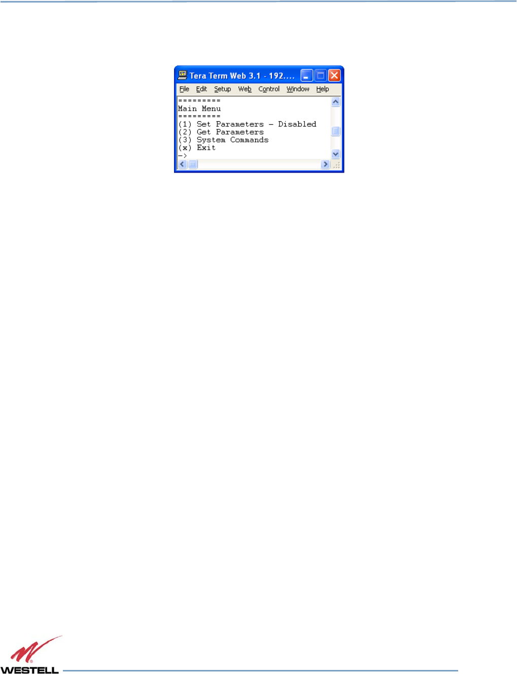
Digital Repeater Line
DSP85 Series
WESTELL.COM
© 2016 Westell Technologies 14 June 2016 Doc. No. 960-1666-MNL rJ
1.877.844.4274 Page 44 of 77
4. After you enter the password, press Enter. The main menu, Figure 4-13, displays. Telnet and serial sessions
both provide access to the same TMI.
Figure
Figure Figure
Figure 4
44
4-
--
-13
1313
13: Main Menu
: Main Menu: Main Menu
: Main Menu
4.3 Modem Interface (Remote Access with Login)
If the repeater is properly equipped, you may use a modem to gain remote access to the repeater. A selection of
modems are available as options.
After you have installed and activated the modem, you can access it from any web browser. Access response time
depends on many factors, some of which are:
• Quality of the connection (RF signal in the case of wireless modems)
• Technology (CDMA, LTE, GPRS, etc.)
• Network congestion (throughput)
When a connection has been established, the login screen shown in both the GUI Serial and Telnet examples displays.
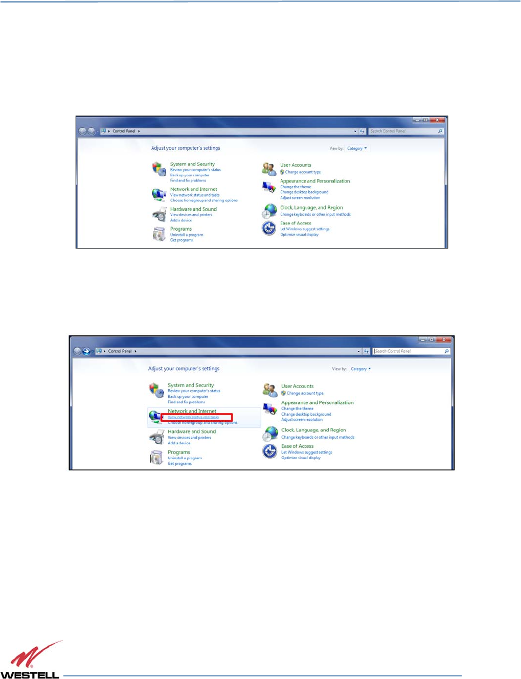
Digital Repeater Line
DSP85 Series
WESTELL.COM
© 2016 Westell Technologies 14 June 2016 Doc. No. 960-1666-MNL rJ
1.877.844.4274 Page 45 of 77
4.4 Additional Tips
Follow the steps in this section to change the TCP/IP settings on your Windows computer.
1. Open your computer’s Control Panel as shown in Figure 4-14.
Figure
Figure Figure
Figure 4
44
4-
--
-14
1414
14: Control Panel
: Control Panel: Control Panel
: Control Panel
2. Click on View network status and tasks, under Network and Internet as shown in Figure 4-15.
Figure
Figure Figure
Figure 4
44
4-
--
-15
1515
15: View Network Status and Tasks
: View Network Status and Tasks: View Network Status and Tasks
: View Network Status and Tasks
3. On the left side, click Change adapter settings as shown in Figure 4-16.
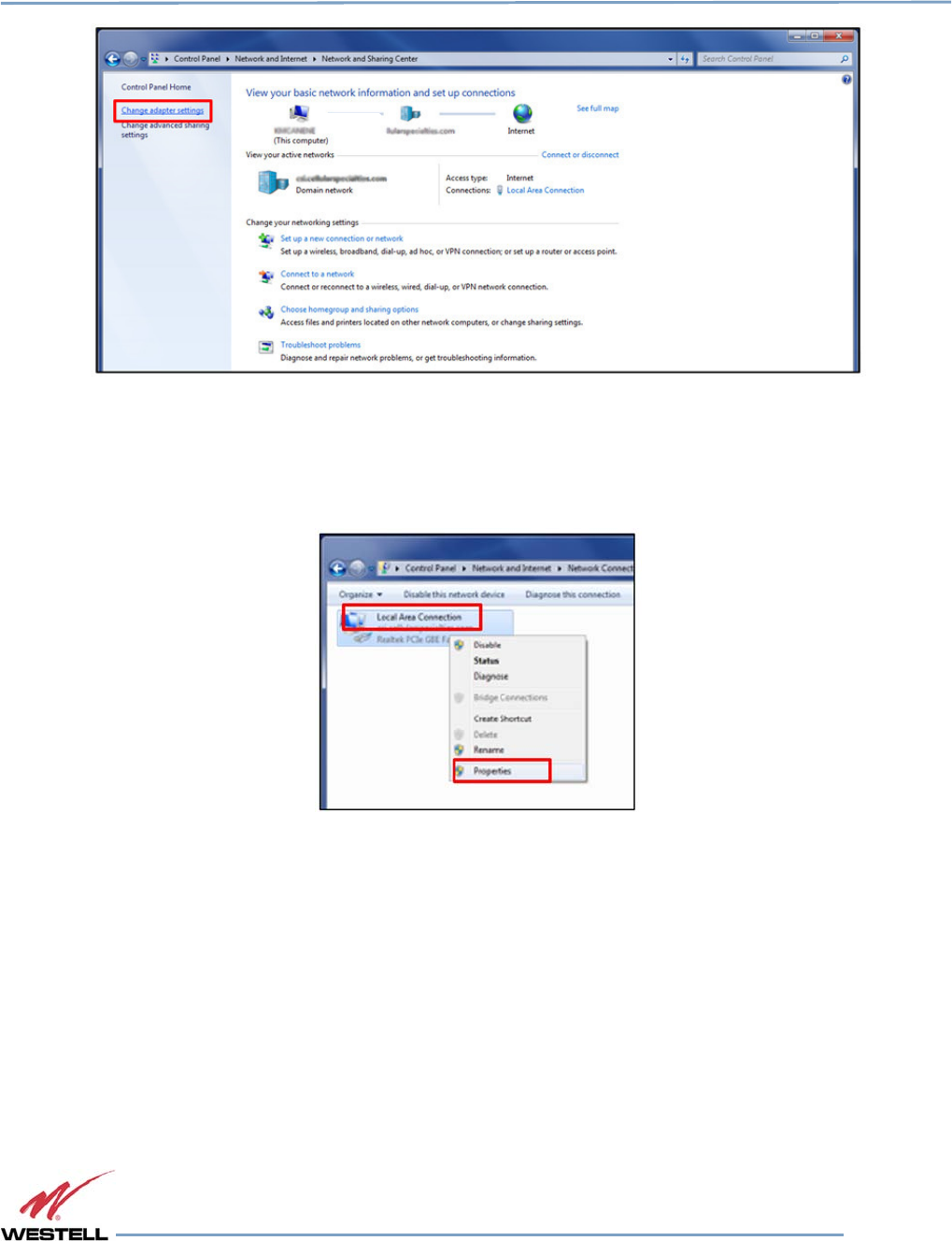
Digital Repeater Line
DSP85 Series
WESTELL.COM
© 2016 Westell Technologies 14 June 2016 Doc. No. 960-1666-MNL rJ
1.877.844.4274 Page 46 of 77
Figure
Figure Figure
Figure 4
44
4-
--
-16
1616
16: Change Adapter Settings
: Change Adapter Settings: Change Adapter Settings
: Change Adapter Settings
4. Right click Local Area Connections and select Properties as shown in Figure 4-17.
Figure
Figure Figure
Figure 4
44
4-
--
-17
1717
17: Local Area Network
: Local Area Network: Local Area Network
: Local Area Network
5. Double click Internet Protocol Version 4 (TCP/IPv4), or highlight Internet Protocol Version 4 (TCP/IPv4)
and select Properties, Figure 4-18.
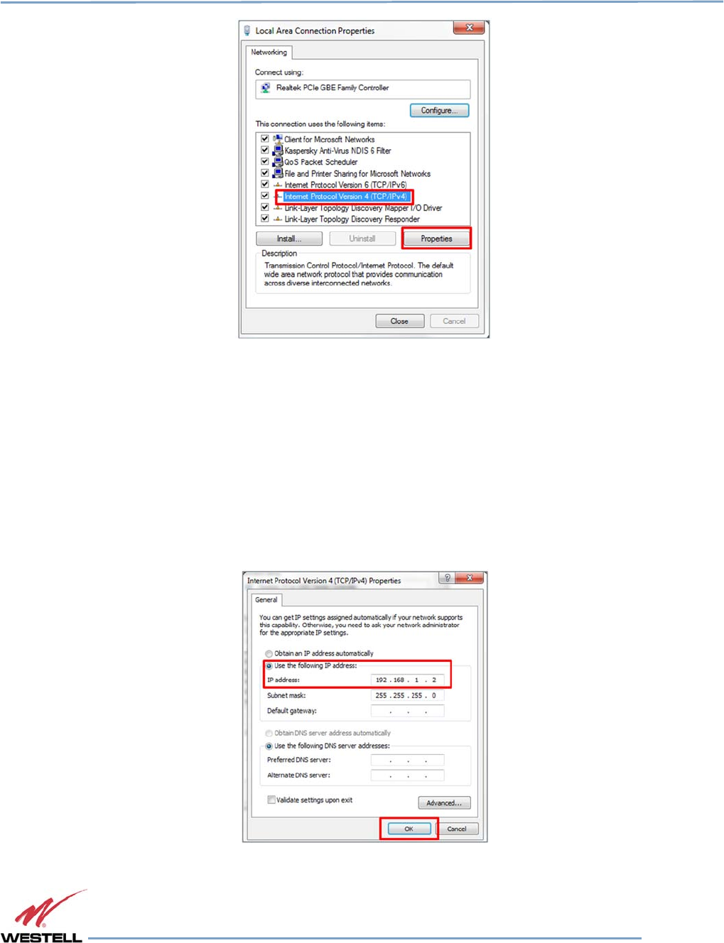
Digital Repeater Line
DSP85 Series
WESTELL.COM
© 2016 Westell Technologies 14 June 2016 Doc. No. 960-1666-MNL rJ
1.877.844.4274 Page 47 of 77
Figure
Figure Figure
Figure 4
44
4-
--
-18
1818
18: Internet Protocol Version 4 (TCP/IPv4)
: Internet Protocol Version 4 (TCP/IPv4): Internet Protocol Version 4 (TCP/IPv4)
: Internet Protocol Version 4 (TCP/IPv4)
6. Click to select the radio button next to Use the following IP address, which will allow you to populate the
IP address and Subnet mask fields. In the IP address enter 192.168.1.2, and click OK, Figure 4-19.
NOTE
The Subnet mask will automatically populate to 255.255.255.0.
Figure
Figure Figure
Figure 4
44
4-
--
-19
1919
19: Enter IP Address
: Enter IP Address: Enter IP Address
: Enter IP Address

Digital Repeater Line
DSP85 Series
WESTELL.COM
© 2016 Westell Technologies 14 June 2016 Doc. No. 960-1666-MNL rJ
1.877.844.4274 Page 48 of 77
7. Click OK, then click OK again.
8. Retry the connection.
Use a crossover ethernet cable (supplied) for web interface access. You must verify that the ethernet port on your
laptop is powered. If your laptop is on battery power, the ethernet port may be inactive by default. If this is the case,
plug the laptop into a 110 VAC source or change the power settings to enable the ethernet port when the laptop is
using battery power.
In some cases, DNS Server setup is required. To do this, log in as bandone through a SSH or serial connection. After
you have logged in, follow the setup instructions. The DNS Address is the IP address of the modem (enter it in twice).

Digital Repeater Line
DSP85 Series
WESTELL.COM
© 2016 Westell Technologies 14 June 2016 Doc. No. 960-1666-MNL rJ
1.877.844.4274 Page 49 of 77
Appendix A
Attenuation and Dynamic Range Guidelines
A.1 Donor Port
If a repeater is installed in an area with very strong wanted and/or unwanted signals, ensure that the overall signal
levels are optimized to be within the best operating range of the repeater. Avoid de-sensing of a nearby base station
site. You can accomplish these goals by properly attenuating the antenna port(s) in the path of the donor antenna(s).
Imagine that the particular repeater deployment is electrically moved farther from the base station using attenuators
that are equivalent to increasing the path loss from the donor antenna to the base station.
The following outcomes may result from the use of attenuators on the donor port(s) of the repeater:
• Uplink output power, as reported by the unit, is reduced by the value of the attenuation, protecting nearby
base stations.
• Downlink signal-to-noise ratio is high at the point of the attenuator, resulting in slight but negligible
reduction in downlink performance.
• Other performance is essentially unchanged.
A.2 Server Port
Server port attenuation may also be necessary, particularly where a powered DAS is present. The selection guidelines
below apply to both server and donor ports. Use a signal generator to measure uplink signal strength properly.
If a signal generator is unavailable, place a test call while under the server antenna with the least path loss to the
repeater. This method should provide reasonable data.
The following potential outcomes result from the use of attenuators on the server port(s) of the repeater:
• downlink output power, as reported by the unit, is reduced by the value of the attenuation.
• Uplink incoming power from the DAS is reduced, along with potentially strong and/or harmful out-of-band
signals (including noise) that are generated by the DAS.
Choose accurate attenuator values to ensure that the maximum total power (higher of composite or in-band input)
applied to the donor and server port(s) does not exceed -25 dBm.

Digital Repeater Line
DSP85 Series
WESTELL.COM
© 2016 Westell Technologies 14 June 2016 Doc. No. 960-1666-MNL rJ
1.877.844.4274 Page 50 of 77
A.3 Dynamic Range Thresholds
Table
Table Table
Table A
AA
A-
--
-1
11
1: Dynamic
: Dynamic : Dynamic
: Dynamic Range Thresholds
Range ThresholdsRange Thresholds
Range Thresholds
Input Signal Max Gain
Input Signal
Max Gain
<-45 dBm 85 dB -32.2 dBm 69 dB
-44.3 dBm 84 dB -31.4 dBm 68 dB
-43.6 dBm 83 dB -30.6 dBm 67 dB
-42.9 dBm 82 dB -29.8 dBm 66 dB
-42.2 dBm 81 dB -29 dBm 65 dB
-41.5 dBm 80 dB -28.2 dBm 64 dB
-40.6 dBm 79 dB -27.4 dBm 63 dB
-39.7 dBm 78 dB -26.6 dBm 62 dB
-38.8 dBm 77 dB -25.8 dBm 61 dB
-37.9 dBm 76 dB -25 dBm 60 dB
-37 dBm 75 dB -24.4 dBm 59 dB*
-36.2 dBm 74 dB -23.8 dBm 58 dB*
-35.4 dBm 73 dB -23.2 dBm 57 dB*
-34.6 dBm 72 dB -22.6 dBm 56 dB*
-33.8 dBm 71 dB -22 dBm ≤55 dB*
-33 dBm 70 dB
*We recommend padding this level, due to potential for fluctuating signal.
-25 dBm is the maximum input signal level that can be applied to the repeater, even if the gain is set to 53.5 dB. Input
signals exceeding these thresholds will result in composite input attenuation, or analog-to-digital converter
protection (ADC protect). Output power is reduced whenever the above thresholds are exceeded by reducing the
gain by 1 dB for each 1 dB that the threshold is exceeded. Do not confuse ADC protect with AGC (automatic gain
control), which reduces gain to prevent in-band (measured) output power from exceeding the specified maximum
output level.
Gain levels that would result in exceeding the rated output power of the repeater, e.g. 65dB of gain applied to an
input signal of -30dBm, will not result in ADC protection, but will result in AGC. Avoid continually operating the
repeater in AGC.
To determine the total power applied to the donor and server ports, reference the composite input values as listed
on the System Status page in the web GUI.
A.4 Large Deltas between In-band and Composite Input Signals
Isolate the best donor site to ensure the least possible delta between in-band and composite downlink signals.
If the (downlink) composite input exceeds the in-band input by more than 3 dB Cellular, or more than 5 dB PCS, the
maximum output power will be reduced.
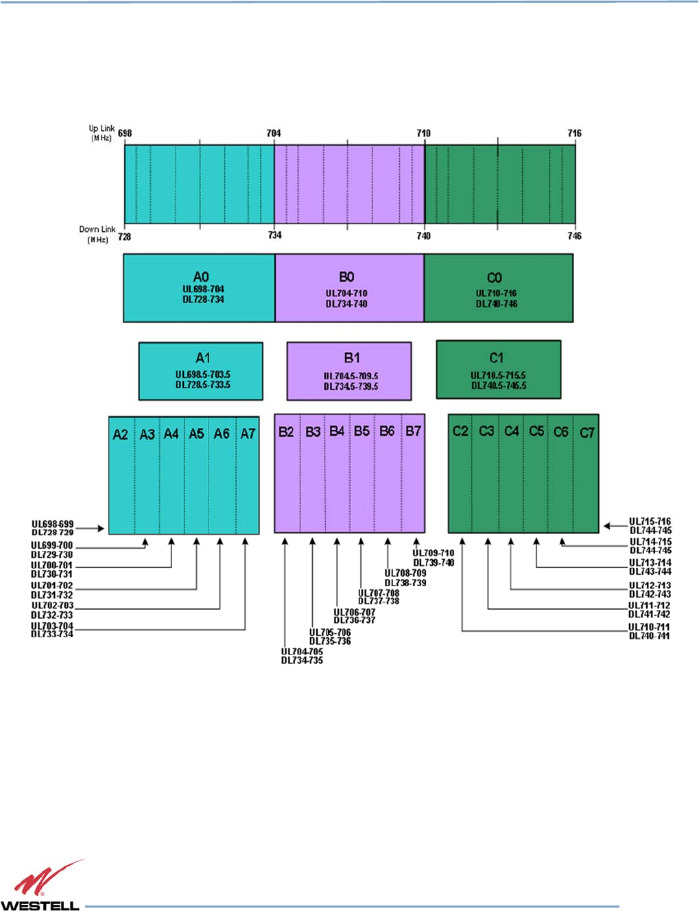
Digital Repeater Line
DSP85 Series
WESTELL.COM
© 2016 Westell Technologies 14 June 2016 Doc. No. 960-1666-MNL rJ
1.877.844.4274 Page 51 of 77
Appendix B
Band Plans
and Filter File Naming Conventions
B.1 Frequency Band Plans
B.1.1
700 MHz Lower A, B and C Band Plan
Figure B-1: 700 MHz Lower A, B and C Band Plan
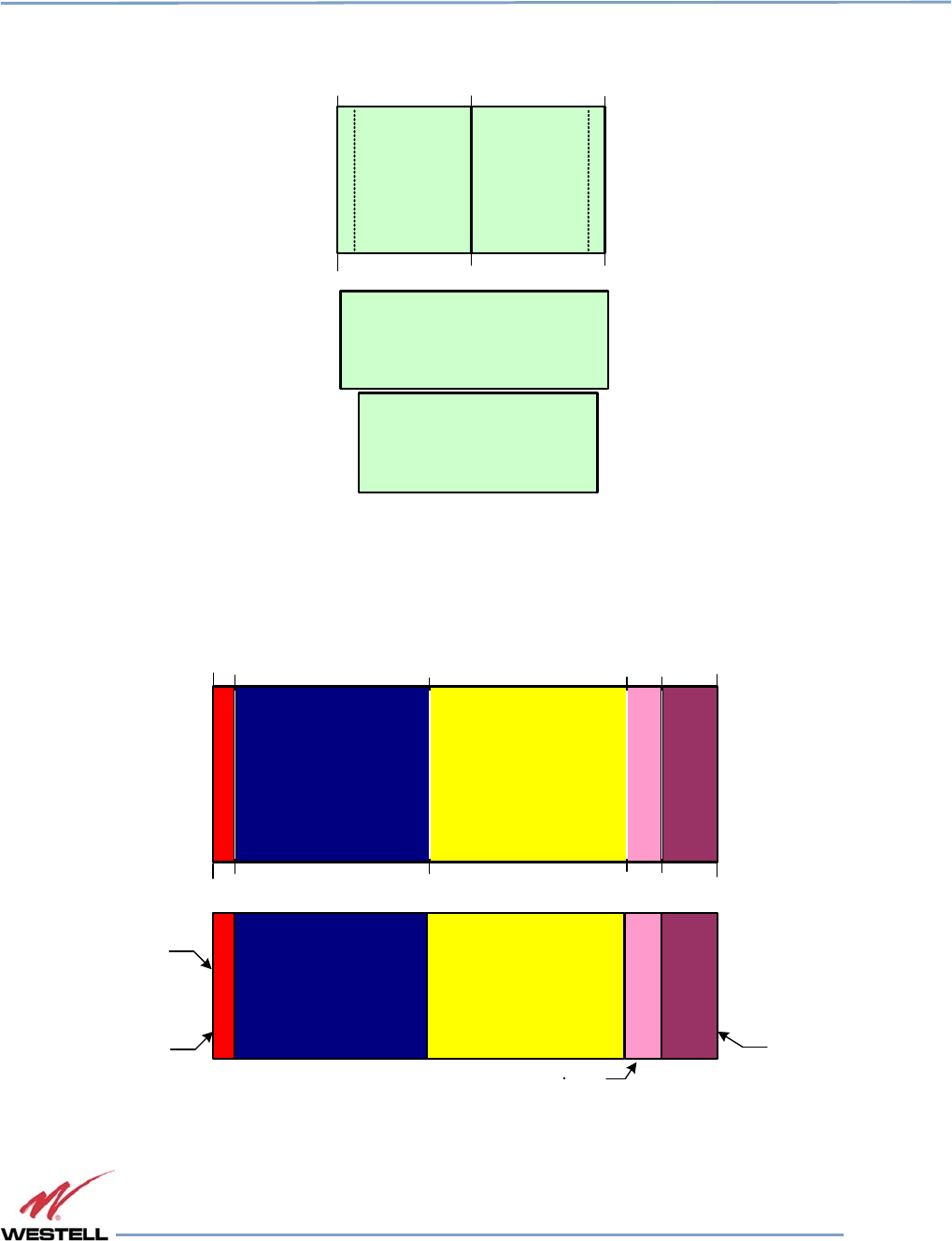
Digital Repeater Line
DSP85 Series
WESTELL.COM
© 2016 Westell Technologies 14 June 2016 Doc. No. 960-1666-MNL rJ
1.877.844.4274 Page 52 of 77
B.1.2
700 MHz Upper C Band Plan
Up Link
(MHz)
Down Link
(MHz) 746
776
C0
UL776-787
DL746-757
C1
UL776.5-786.5
DL746.5-756.5
787
757
781.5
751.5
Figure B-2: 700 MHz Upper C Band Plan
B.1.3
Cellular Frequency Band Plan
824
Uplink
(MHz)
Downlink
(MHz)
869
825
870
835
880
845
890
846.5
891.5
849
894
B’
A’
B
A
A”
UL 825-835
DL 870-880
UL 824-825
DL 869-870
UL 835-845
DL 880-890
UL 845-846.5
DL 890-891.5
UL 846.5-849
DL 891.5-894
Figure B-3:
Cellular Frequency Band
Plan
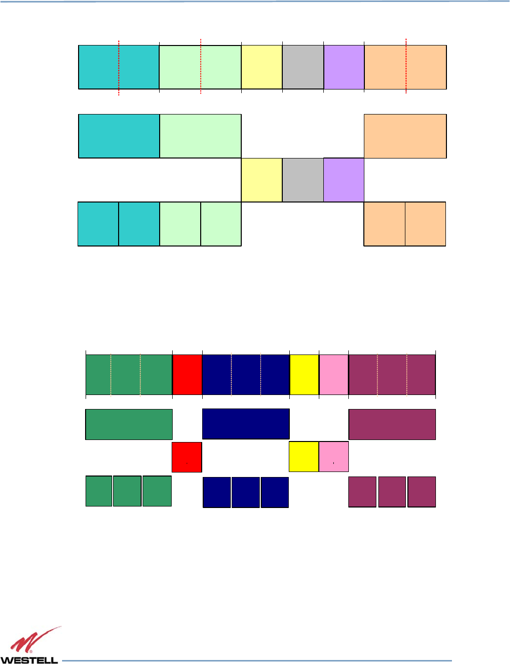
Digital Repeater Line
DSP85 Series
WESTELL.COM
© 2016 Westell Technologies 14 June 2016 Doc. No. 960-1666-MNL rJ
1.877.844.4274 Page 53 of 77
B.1.4
AWS Frequency Band Plan
Mobile
(MHz)
Base
(MHz) 2110
1710 1720
2120
1730 1735 1740 1745 1755
2130 2135 2140 2145 2155
A0 F0
DL2110-2120
UL1735-1740
DL2135-2140
UL1745-1755
DL2145-2155
F1
UL1710-1720
B0
UL1720-1730
DL2120-2130
A1 A2
UL1710-1715
DL2110-2115
UL1715-1720
DL2115-2120
B2
UL1725-1730
DL2125-2130
C0 D0 E0
UL1730-1735
DL2130-2135
UL1740-1745
DL2140-2145
F2
UL1745-1750
DL2145-2150
UL1750-1755
DL2150-2155
B1
UL1720-1725
DL2120-2125
Figure B-4: AWS Frequency Band Plan
B.1.5
Canadian PCS Frequency Band Plan
1850
1930
1865 1870 1885 1890 1895 1910
1945 1950 1965 1970 1975 1990
A0
A1 A2 A3
D0
B0
B1 B2 B3
E0 F0
C0
C1 C2 C3
UL 1850-1865
DL 1930-1945
UL 1865-1870
DL 1945-1950
UL 1870-1885
DL 1950-1965
UL 1885-1890
DL 1965-1970
UL 1890-1895
DL 1970-1975
UL 1895-1910
DL 1975-1990
UL 1895-1900
DL 1975-198 0
UL 1900-1905
DL 1980-1985
UL 1905-1910
DL 1985-1990
UL 1870-1875
DL 1950-1955
UL 1875-1880
DL 195 5-1960
UL 1880-1885
DL 1960-1965
UL 1850-185 5
DL 1930-193 5
UL 185 5-1860
DL 1935-1940
UL 1860-1865
DL 1940-1945
Uplink
(MHz)
Downlink
(MHz)
Figure B-5: Canadian PCS Frequency Band Plan
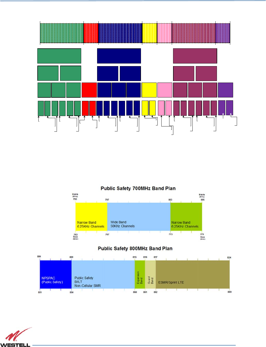
Digital Repeater Line
DSP85 Series
WESTELL.COM
© 2016 Westell Technologies 14 June 2016 Doc. No. 960-1666-MNL rJ
1.877.844.4274 Page 54 of 77
B.1.6
US PCS Frequency Band Plan
Uplink
(MHz)
Downlink
(MHz)
1850
1930
1865 1870 1885 1890 1895 1910
1945 1950 1965 1970 1975 1990
UL 1902.5-1910
DL 1982.5-1990
UL 190 0-1905
DL 198 0-1985
UL 190 5-1910
DL 198 5-1990
1915
1995
G0
A0
A1
A2
A3 A4 A5
D0
B0
B1B2
B3 B4 B5
E0 F0
C0
C1C2
C3 C4 C5
C6 C7 C9
UL 1850-1865
DL 1930-1945
UL 1865-1870
DL 1945-1950
UL 1870-1885
DL 1950-1965
UL 1885-1890
DL 1965-1970
UL 1890-1895
DL 1970-1975
UL 1895-1910
DL 1975-1990
UL 1895-1902.5
DL 1975-1982.5
UL 1902.5-1910
DL 1982.5-1990
UL 1895-190 0
DL 1975-1980
UL 1900-1905
DL 1980-1985
UL 190 5-1910
DL 198 5-1990
UL 1895-1897.5
DL 1975-1977.5
UL 1897.5-1900
DL 1977.5-1980
UL 1900-1902.5
DL 1980-1982.5
UL 1902.5-1905
DL 1982.5-1985
C8
UL 1870-1877.5
DL 1950-1957.5
UL 1877.5-1885
DL 1957.5-1965
UL 1850-1857.5
DL 1930-1937.5
UL 1857.5-1865
DL 1937.5-1945
UL 187 0-1875
DL 195 0-1955
UL 187 5-1880
DL 195 5-1960
UL 1880-1885
DL 1960-1965
UL 1850-1855
DL 1930-1935
UL 1855-1860
DL 193 5-1940
UL 186 0-1865
DL 194 0-1945
C11C10
B6 B7 B9
B8 B11
B10
A6 A7 A9
A8 A11A10 D1
D2 E1E2 F1F2
UL 1905-1907.5
DL 1985-1987.5
UL 1907.5-1910
DL 1987.5-1990
UL 1870-1872.5
DL 1950-1952.5
UL 1872.5-1875
DL 1952.5-1955
UL 1875-1877.5
DL 1955-1957.5
UL 1877.5-1880
DL 1957.5-1960
UL 1880-1882.5
DL 1960-1962.5
UL 1882.5-1885
DL 1962.5-1965
UL 1850-1852.5
DL 1930-1932.5
UL 1852.5-1855
DL 1932.5-1935
UL 1855-1857.5
DL 1935-1937.5
UL 1857.5-1860
DL 1935-1937.5
UL 1860-1862.5
DL 1940-1942.5
UL 1862.5-1865
DL 1942.5-1945
UL 1885-1887.5
DL 1965-1967.5
UL 1887.5-1890
DL 1967.5-1970
UL 1890-1892.5
DL 1970-1972.5
UL 1892.5-1895
DL 1972.5-1975
UL 1865-1867.5
DL 1945-1947.5
UL 1867.5-1870
DL 1947.5-1950
G2
*
G block not
currently supported
in CSI repeaters.
*
Figure B-6: US PCS Frequency Band Plan
B.1.7
Public Safety Bands
Figure B-7: Public Safety Bands
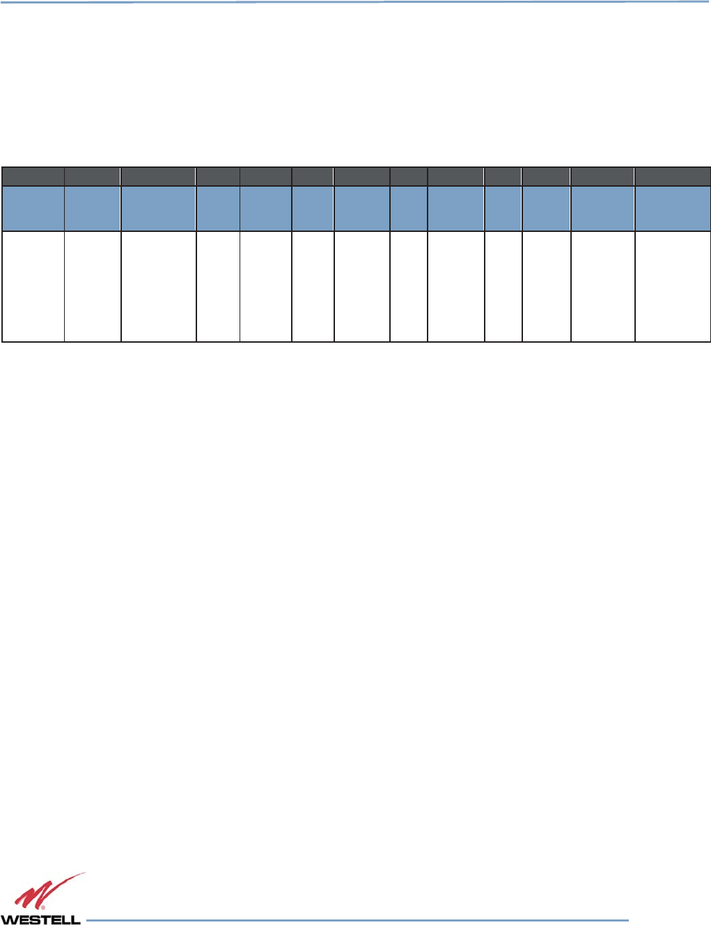
Digital Repeater Line
DSP85 Series
WESTELL.COM
© 2016 Westell Technologies 14 June 2016 Doc. No. 960-1666-MNL rJ
1.877.844.4274 Page 55 of 77
B.2 Filter File Naming Conventions
B.2.1
700 MHz Filter Naming Convention
Westell Technologies digital repeaters use an alphanumeric file naming convention for its filter files. The descriptions
below will allow you to understand the methodology to determine the desired file for your application.
Table B-1:
700 MHz Filter Naming
Convention
Column:
1
2
3
4
5
6
7
8
9
1
0
11
12
Definition:
Band Mod
type
Block
1
Sub-
block
1
Block
2
Sub-
block
2
Block
3
Sub-
block
3
Block
4
Sub
-
block
Separator
Variant
l=
700MHZ
e=
E-UTRA
(Upper) l=
E-UTRA
(Lower)
A - C
0=Full
1-
7=Sub
A - C
0=Full
1-7=Sub
A -
C
0=Full
1-7=Sub
A -
C
0=Full
1-
7=Sub
- 0=Standard
NOTE
Modulation type determines the guard band at the edges of each passband. The
modulation type field will also be used to indicate a carrier who has a unique sub-
block designation.
Up to four sub-blocks may be defined, resulting in a maximum filename length.
All variant/guard band designators other than 0 (zero) and F are user-defined custom filters.
700 MHz examples
llA1B1-0 = (700 MHz band, E-UTRA mod type, Lower A1, B1, with standard guard band). leC0-0 = (700MHz band, E-
UTRA mod type, Upper C, with standard guard band).
llC1-0 = (700 MHz band, E-UTRA mod type, Lower C1, with standard guard band).
700 MHz upper block
Uplink Downlink
C0 776-787 746-757
700 MHz upper sub-block
Uplink Downlink
C1 776.5-786.5 746.5-756.5

Digital Repeater Line
DSP85 Series
WESTELL.COM
© 2016 Westell Technologies 14 June 2016 Doc. No. 960-1666-MNL rJ
1.877.844.4274 Page 56 of 77
B.2.2
Cellular Filter File Naming Convention
Table B-2: Cellular Filter File Naming Convention
Column:
1
2
3
4
5
6
7
8
9
10
11
12
Definition: Band Mod
type
Block 1
Sub-block
1
Block 2 Sub-block
2
Block 3
Sub-block
3
Block 4
Sub-block
4
Separator
Variant
c=Cell
g=GSM
c=CDMA
A - B 0=Full
p=Prime
d=Double
prime
A - B
0=Full
p=Prime
d=Double
prime
A - B 0=Full
p=Prime
d=Double
prime
A - B 0=Full
p=Prime
d=Double
prime
- 0=Standard
Cell example
ccAdAp-0 = (Cellular band, CDMA mod type, A” and A’ with standard guard band).
Cellular blocks
Uplink Downlink
A0 825-835 870-880
B0 835-845 880-890
Cellular sub-blocks
Uplink Downlink
A’ 845-846.5 890-891.5
A” 824-825 869-870
B’ 846.5-849 891.5-894

Digital Repeater Line
DSP85 Series
WESTELL.COM
© 2016 Westell Technologies 14 June 2016 Doc. No. 960-1666-MNL rJ
1.877.844.4274 Page 57 of 77
B.2.3
Canadian PCS Filter File Naming Convention
Table B-3:
Canadian PCS Filter
File
Naming
Convention
Column:
1
2
3
4
5
6
7
8
9
10
11
12
Definition:
Band
Mod
type
Block 1
Sub-
block 1
Block 2
Sub-block
2
Block 3
Sub-
block 3
Block 4
Sub-block
4
Separator
Variant
p=PCS
u=UMTS
See
note
A - F
0=Full
1-3=Sub
A - F
0=Full
1-3=Sub
A - F
0=Full
1-3=Sub
A - F
0=Full
1-3=Sub
-
can=
Custom
Canadian
filter
Canadian PCS example
puE0F0-can = (PCS band, UMTS mod type, E full, F full, Canadian Custom filter).
Canadian PCS blocks
Uplink Downlink
A0 1850-1865 1930-1945
D0 1865-1870 1945-1950
B0 1870-1885 1950-1965
E0 1885-1890 1965-1970
F0 1890-1895 1970-1975
C0 1895-1910 1975-1990
Canadian PCS sub-blocks
Uplink Downlink
A1 1850-1855 1930-1935
A2 1855-1860 1935-1940
A3 1860-1865 1940-1945
B1 1870-1875 1950-1955
B2 1875-1880 1955-1960
B3 1880-1885 1960-1965
C1 1895-1900 1975-1980
C2 1900-1905 1980-1985
C3 1905-1910 1985-1990

Digital Repeater Line
DSP85 Series
WESTELL.COM
© 2016 Westell Technologies 14 June 2016 Doc. No. 960-1666-MNL rJ
1.877.844.4274 Page 58 of 77
B.2.4
US PCS Filter File Naming Convention
Table B-4: US
PCS Filter
File
Naming
Convention
Column:
1
2
3
4
5
6
7
8
9
10
11
12
Definition: Band Mod
type
Block 1
Sub-block
1
Block 2 Sub-block
2
Block 3
Sub-block
3
Block 4
Sub-block
4
Separator
Variant
p=PCS g=gsm A - F 0=Full
1-11=Sub
A - F 0=Full
1-11=Sub
A - F 0=Full
1-11=Sub
A - F 0=Full
1-11=Sub
- 0=Standard
US PCS example
pcA1C0E0F2-0 = (PCS band, CDMA mod type, A1, C full, E full, F2 with standard guard band).
US PCS blocks
Uplink Downlink
A0 1850-1865 1930-1945
D0 1865-1870 1945-1950
B0 1870-1885 1950-1965
E0 1885-1890 1965-1970
F0 1890-1895 1970-1975
C0 1895-1910 1975-1990

Digital Repeater Line
DSP85 Series
WESTELL.COM
© 2016 Westell Technologies 14 June 2016 Doc. No. 960-1666-MNL rJ
1.877.844.4274 Page 59 of 77
US PCS sub-blocks
Uplink Downlink
A2 1850-1857.5 1930-1937.5
A1 1857.5-1865 1937.5-1945
A3 1850-1855 1930-1935
A4 1855-1860 1935-1940
A5 1860-1865 1940-1945
D2 1865-1867.5 1945-1947.5
D1 1867.5-1870 1947.5-1950
B2 1870-1877.5 1950-1957.5
B1 1877.5-1885 1957.5-1965
B3 1870-1875 1950-1955
B4 1875-1880 1955-1960
B5 1880-1885 1960-1965
E2 1885-1887.5 1965-1967.5
E1 1887.5-1890 1967.5-1970
F2 1890-1892.5 1970-1972.5
F1 1892.5-1895 1972.5-1975
C2 1895-1902.5 1975-1982.5
C1 1902.5-1910 1982.5-1990
C3 1895-1900 1975-1980
C4 1900-1905 1980-1985
C5 1905-1910 1985-1990
NOTE
Modulation type determines the guard band at the edges of each passband. The
modulation type field will also be used to indicate a carrier who has a unique sub-
block designation.
Up to four sub-blocks may be defined, resulting in a maximum filename length.
All variant/guard band designators other than 0 (zero) and F are user-defined custom filters.

Digital Repeater Line
DSP85 Series
WESTELL.COM
© 2016 Westell Technologies 14 June 2016 Doc. No. 960-1666-MNL rJ
1.877.844.4274 Page 60 of 77
B.2.5
AWS Filter Naming Convention
Column:
1
2
3
4
5
6
7
8
9
10
11
12
Definition:
Band Mod type
Block
1
Sub-block
1
Block
2
Sub-block
2
Block
3
Sub- block
3
Block
4
Sub-block
4
Separator
Variant
a=AWS g=gsm
c=CDMA
w=WCDMA
e=E-UTRA
l=LTE
A - F 0=Full
1-2=Sub
A - F 0=Full
1-2=Sub
A - F 0=Full
1-2=Sub
A - F 0=Full
1-2=Sub
- 0=Standard
AWS example
acA1C0E0F2-0 = (AWS band, CDMA mod type, A1, C full, E full, F2 with standard guard band).
AWS blocks
Uplink Downlink
A0 1710-1720 2110-2120
B0 1720-1730 2120-2130
C0 1730-1735 2130-2135
D0 1735-1740 2135-2140
E0 1740-1745 2140-2145
F0 1745-1755 2145-2155
AWS sub-blocks
Uplink Downlink
A1 1710-1715 2110-2115
A2 1715-1720 2115-2120
B1 1720-1725 2120-2125
B2 1725-1730 2125-2130
F1 1745-1750 2145-2150
F2 1750-1755 2150-2155
NOTE
Modulation type determines the guard band at the edges of each passband. The
modulation type field will also be used to indicate a carrier who has a unique sub-
block designation.
Up to four sub-blocks may be defined, resulting in a maximum filename length of 12 characters. All variant/guard
band designators other than 0 (zero) are user defined custom filters.
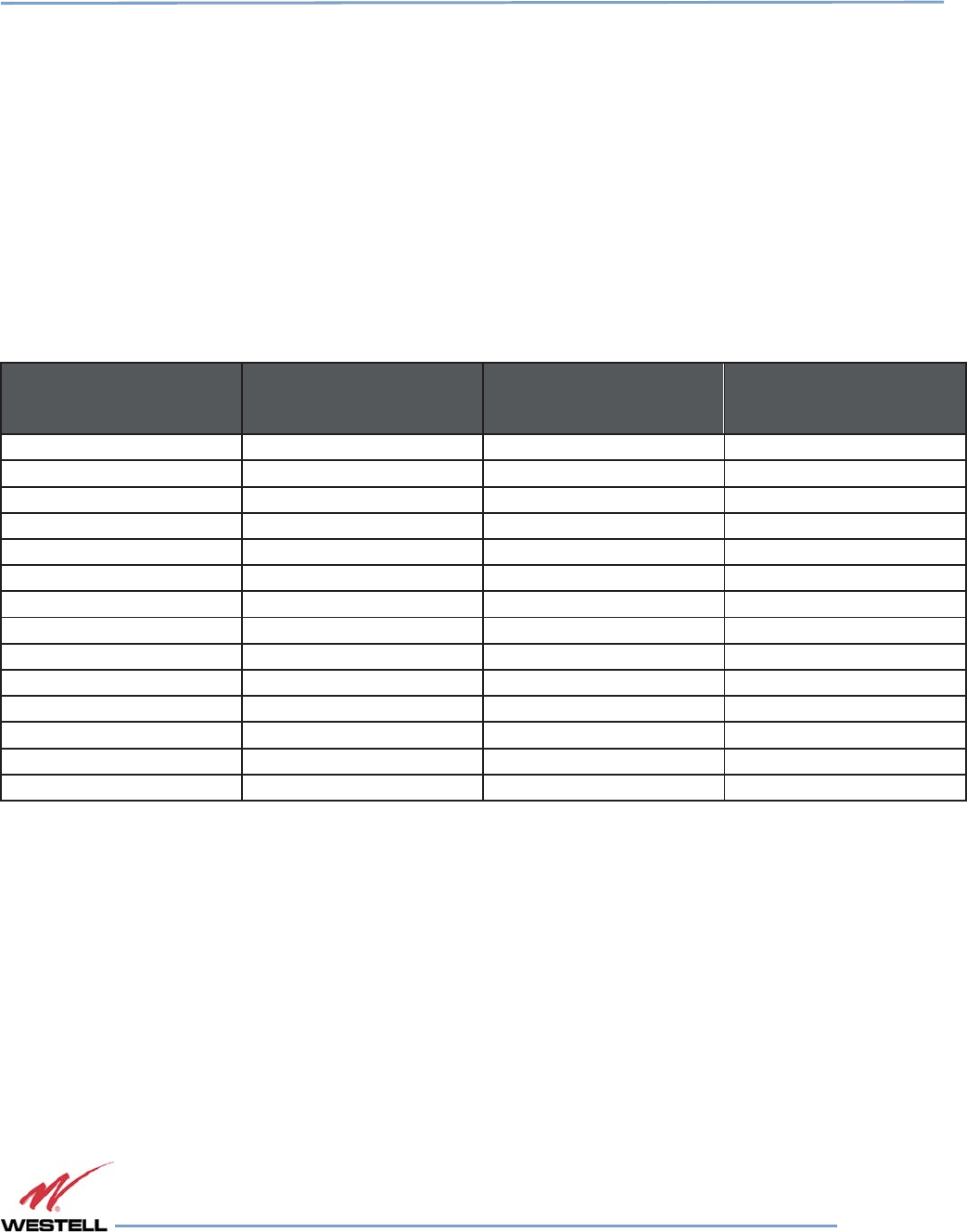
Digital Repeater Line
DSP85 Series
WESTELL.COM
© 2016 Westell Technologies 14 June 2016 Doc. No. 960-1666-MNL rJ
1.877.844.4274 Page 61 of 77
Appendix C
LTE Attenuator and Installation Notes
C.1 Important LTE Attenuator and Installation Notes - Donor and Server Isolation
Inadequate isolation between the outside and inside antennas may cause regenerative feedback in the system.
Carefully consider the layout and placement of the system. Set repeater gain well below line of sight donor path loss,
as shown in C.1.1 Line of Sight Propagation Path Loss Table. Higher gain settings may be possible if the internal
building structure and system layout adds additional attenuation and the installer is confident about the values of
that attenuation.
C.1.1
Line of Sight Propagation Path Loss Table
Table
Table Table
Table C
CC
C-
--
-1
11
1:
: :
: Line
LineLine
Line
of
ofof
of
Sight
SightSight
Sight
Propagation
PropagationPropagation
Propagation
Path
PathPath
Path
Loss
LossLoss
Loss
Table
TableTable
Table
Distance between donor and
server antenna Free space path loss Max gain
2
Max gain with 20 dB
attenuation from building
structure
2
10 m
1
50 dB
1
55
dB
1
55
dB
1
40 m
1
62 dB
1
55
dB
1
67
dB
1
60 m
1
65.5 dB
1
55
dB
1
70.5
dB
1
100
m
70
dB
55
dB
75
dB
120
m
71.5
dB
56.5
dB
76.5
dB
143
m
73
dB
58
dB
78
dB
160
m
74
dB
59
dB
79
dB
180
m
75
dB
60
dB
80
dB
200
m
76
dB
61
dB
81
dB
239
m
77.5
dB
62.5
dB
82.5
dB
268
m
78.5
dB
63.5
dB
83.5
dB
284
m
79
dB
64
dB
84
dB
300
m
79.5
dB
64.5
dB
84.5
dB
318
m
80
dB
65
dB
85
dB
NOTE1
Antenna separation under 100 meters requires additional attenuation greater than
20 dB.
NOTE
2
Maximum gain assumes no loss or gain in donor seen, coax distribution, or active
DAS.

Digital Repeater Line
DSP85 Series
WESTELL.COM
© 2016 Westell Technologies 14 June 2016 Doc. No. 960-1666-MNL rJ
1.877.844.4274 Page 62 of 77
Appendix D
Mechanical and Electrical Specifications
D.1 Digital Repeater Mechanical and Electrical Specifications
D.1.1
Mechanical Specifications
Table D-1: Mechanical Specifications
Parameters Single Band Dual Band
Repeater Dimensions
DSP85/DSP85-201 18.5 x 10 x 4.7 in (approx.) 19.25 x 18.6 x 4.7 in (approx.)
DSP85N 20 x 16 x 6 in (approx.) -
DSP85-250 and 251 19 x 18 x 3.5 in (2U) (approx.) 19 x 18 x 3.5 in (2U) (approx.)
DSP95-255 18.63 x 19.25 x 5.25 in (3U)
(approx.)
18.63 x 19.25 x 5.25 in (3U)
(approx.)
Weight/Shipping Weight
DSP85/DSP85-201 23 lbs / 28 lbs (approx.) 42 lbs / 50 lbs (approx.)
DSP85N 23 lbs / 28 lbs (approx.) -
DSP85-250 and 251 17 lbs / 27 lbs (approx.) 21 lbs / 31 lbs (approx.)
DSP95-255 24 lbs / 28 lbs (approx.) 34 lbs / 38 lbs (approx.)
Connectors N-female or 4.3-10 N-female or 4.3-10
Thermal management Convection cooled Convection cooled
Surface coating Powder
coat
Powder
coat
Color Satin
black
Satin
black
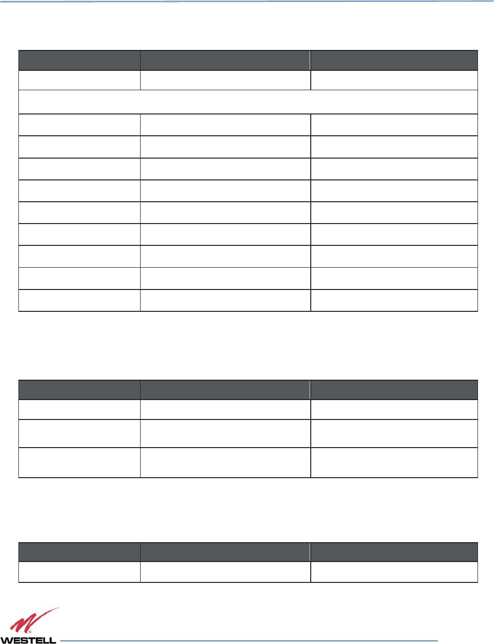
Digital Repeater Line
DSP85 Series
WESTELL.COM
© 2016 Westell Technologies 14 June 2016 Doc. No. 960-1666-MNL rJ
1.877.844.4274 Page 63 of 77
D.1.2
Electrical Specifications
Table D-2: Electrical Specifications
Parameters Single Band Dual Band
Passband Options 1 MHZ – full band 1 MHZ – full band
Linear output power (typical)
½ Watt 27dBm 27dBm
1 Watt 30dBm 30dBm
5 Watts 37dBm 37dBm
Noise figure @ max. gain 5.0 dB 5.0 dB
Propagation Delay <2.5 microseconds <2.5 microseconds
Gain Adjustment Range 30dB, 0.5 dB steps 30dB, 0.5 dB steps
VSWR <1.5:1 <1.5:1
Spurious emissions <-13dBm <-13dBm
Input/output impedance 50 ohms 50 ohms
D.1.3
Power Requirements
Table D-3: Power Requirements
Parameters Single Band Dual Band
½ Watt 0.9 Amps @ 120 VAC / 0.5 Amps @
230 VAC
1.5 Amps @ 120 VAC / 0.8 Amps @
230 VAC
1 Watt 0.7 Amps @ 120 VAC / 0.6 Amps @
230 VAC
1.7 Amps @ 120 VAC / 0.9 Amps @
230 VAC
5 Watt 1.2 Amps @ 120 VAC / 0.7 Amps @
230 VAC
2.0 Amps @ 120 VAC / 1.1 Amps @
230 VAC
D.1.4
Environmental Requirements
Table D-4: Environmental Requirements
Parameters Single Band Dual Band
Operating Temperature 10°C to 50° C
(50°
F to
122°
F) 10°C to 50° C
(50°
F to
122°
F)
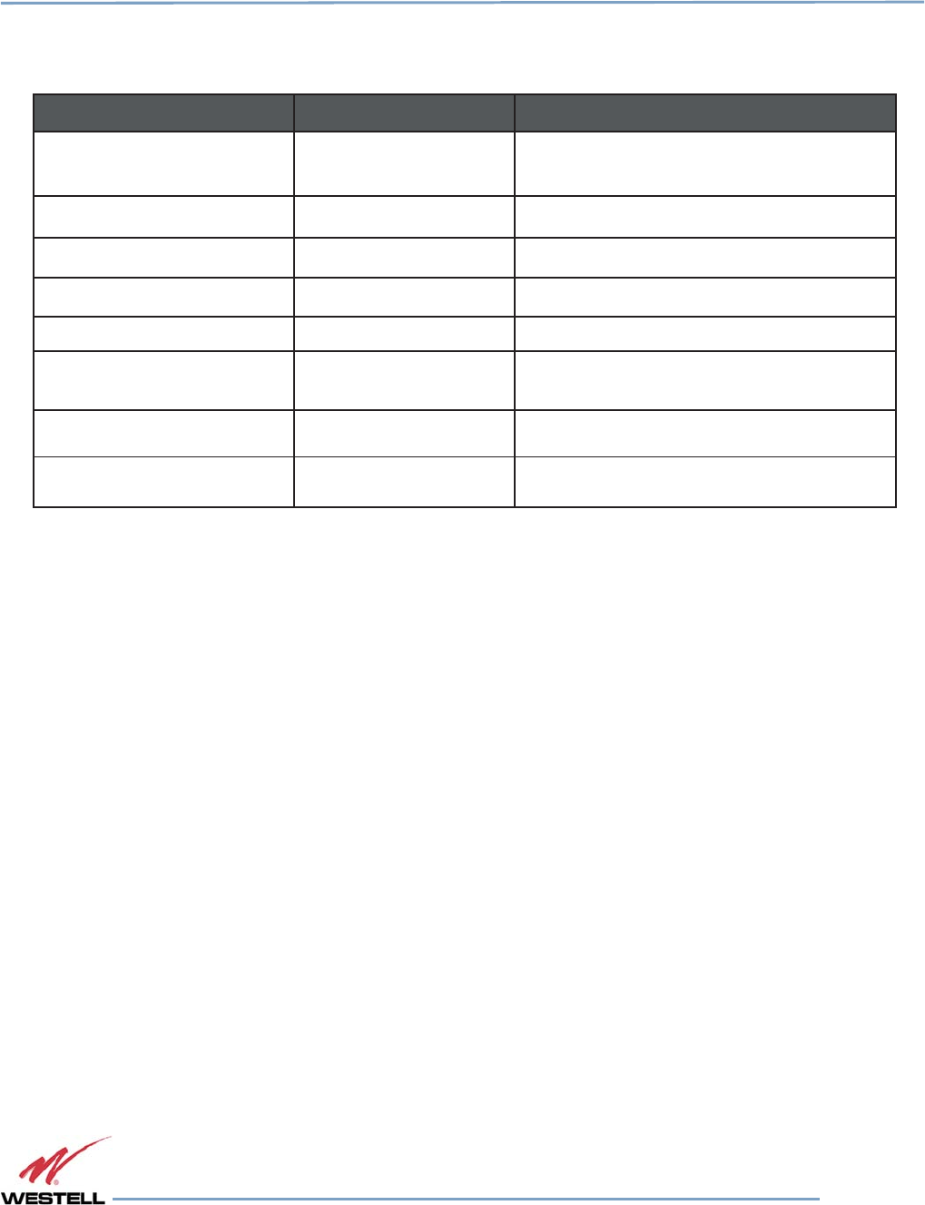
Digital Repeater Line
DSP85 Series
WESTELL.COM
© 2016 Westell Technologies 14 June 2016 Doc. No. 960-1666-MNL rJ
1.877.844.4274 Page 64 of 77
D.1.5
Operating Power Parameters
Table D-5: Operating Power Parameters
Parameters Specifications Notes
Maximum RF input power
without damage 10
dBm
Linear
gain
85
dB
Factory calibrated gain
Pass band ripple ±1.5
dB
Automatic gain control (AGC) 30 dB max range In 0.5 dB steps
Manual gain control 53.5 dB to 85 dB In 0.5 dB steps
OIP3 41
dBm
Measured with two CW tones at 14
dBm/
tone
RMS vector error (EVM) 3%
max
TDMA, EDGE, W-CDMA, CDMA2000
CDMA RHO
0.98
min
CDMA2000, 1x-EVD0
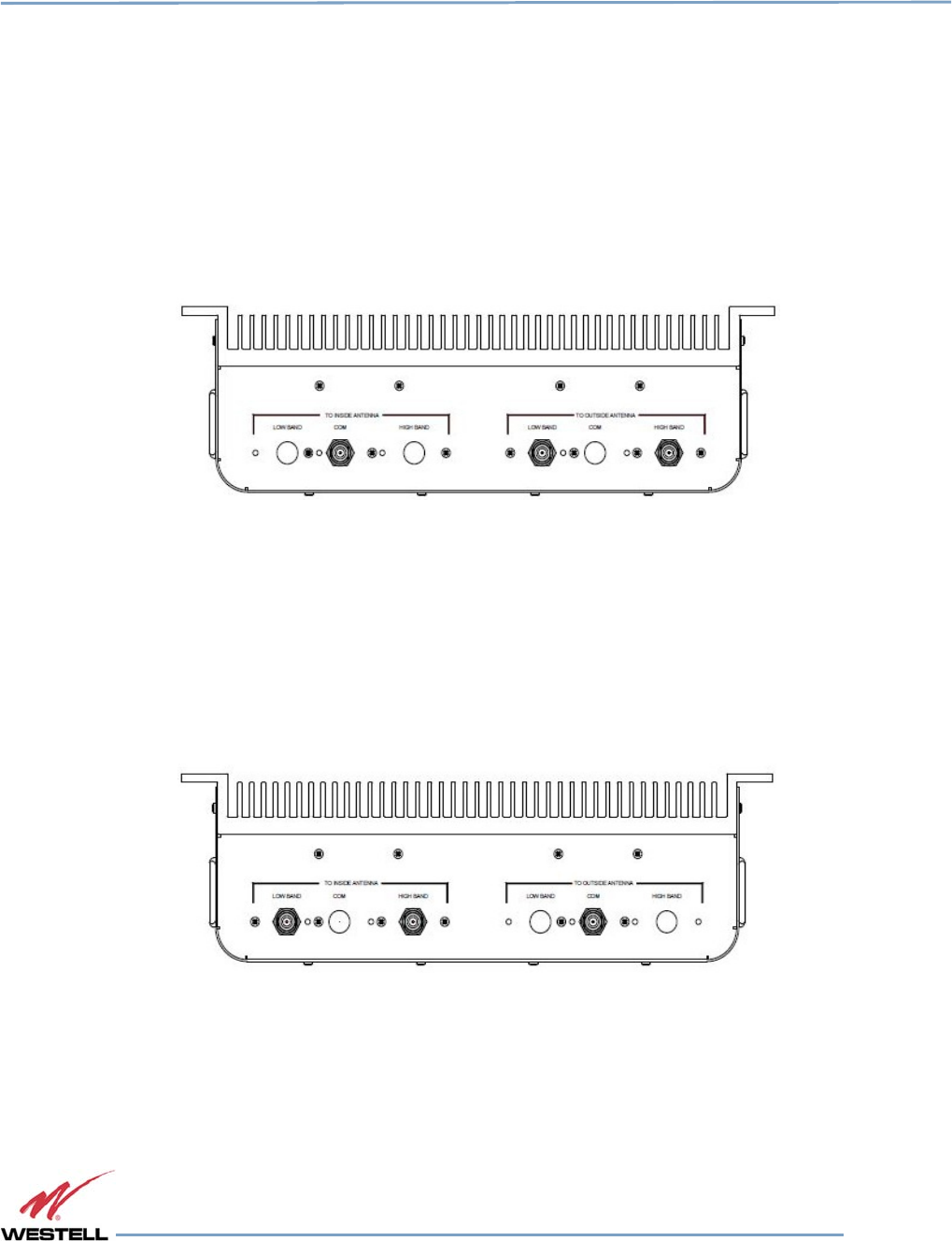
Digital Repeater Line
DSP85 Series
WESTELL.COM
© 2016 Westell Technologies 14 June 2016 Doc. No. 960-1666-MNL rJ
1.877.844.4274 Page 65 of 77
Appendix E
Port Configurations
E.1 Digital Repeater Port Configurations, Original Series
E.1.1
Dual-band D2:D1 Port Configuration
Input: Two single-band duplex ports, one from the low-band donor antenna and one from the high-band donor
antenna.
Output: One dual-band duplex port to the server antennas.
Figure E-1: Dual-band D2:D1 Port Configuration
E.1.2
Dual-band D1:D2 Port Configuration
Input: One dual-band duplex port from dual-band donor antenna.
Output: Two single-band duplex ports, one to the low-band server antennas and one to the high-band server
antennas.
Figure E-2: Dual-band D1:D2 Port Configuration
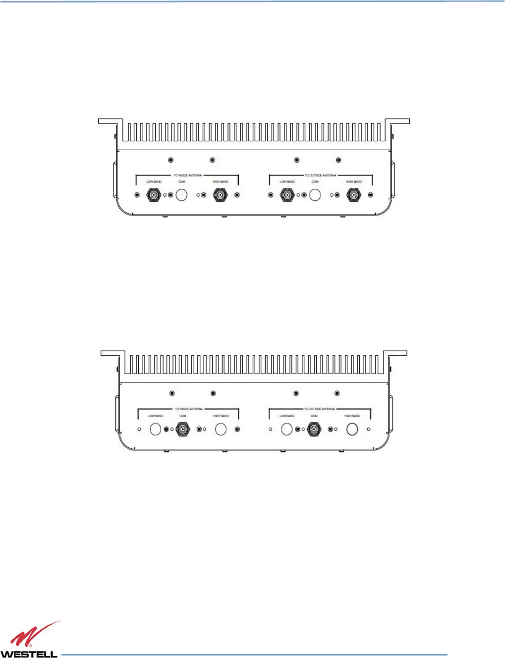
Digital Repeater Line
DSP85 Series
WESTELL.COM
© 2016 Westell Technologies 14 June 2016 Doc. No. 960-1666-MNL rJ
1.877.844.4274 Page 66 of 77
E.1.3
Dual-band D2: D2 Port Configuration
Input: Two single-band duplex ports, one from the low-band donor antenna and one from the high-band donor
antenna.
Output: Two single-band duplex ports, one to the low-band server antennas and one to the high-band server
antennas.
Figure E-3: Dual-band D2: D2 Port Configuration
E.1.4
Dual-band D1:D1 Port Configuration
Input: One dual-band duplex port from dual-band donor antenna.
Output: One dual-band duplex port to dual-band server antennas.
Figure E-4: Dual-band D1:D1 Port Configuration
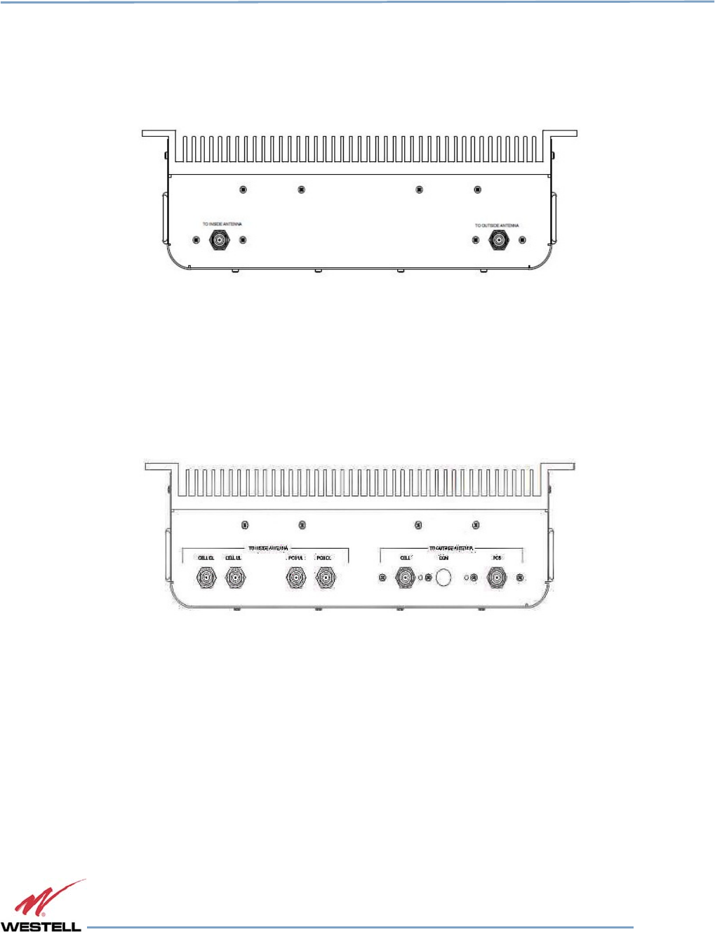
Digital Repeater Line
DSP85 Series
WESTELL.COM
© 2016 Westell Technologies 14 June 2016 Doc. No. 960-1666-MNL rJ
1.877.844.4274 Page 67 of 77
E.1.5
Single-band D1:D1 Port Configuration
Input: One single-band duplex port from donor antenna.
Output: One single-band duplex port to server antennas.
Figure E-5: Single-band D1:D1 Port Configuration
E.1.6
Dual-band D2:S4 Port Configuration
Input: Two single-band duplex ports from the donor antenna, one from the high-band, one from the low-band.
Output: Four dingle-band simplex ports, two uplink, two downlink, one uplink and one downlink for each band.
Figure E-6: Dual-band D2:S4 Port Configuration
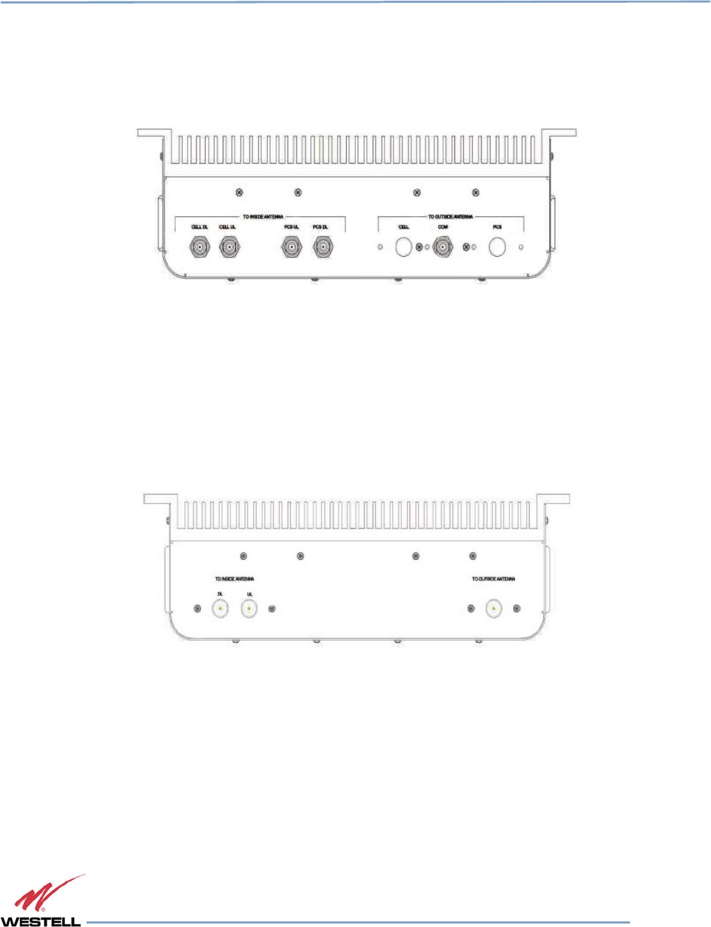
Digital Repeater Line
DSP85 Series
WESTELL.COM
© 2016 Westell Technologies 14 June 2016 Doc. No. 960-1666-MNL rJ
1.877.844.4274 Page 68 of 77
E.1.7
Dual-band D1:S4 Port Configuration
Input: One dual-band duplex port from dual-band donor antenna.
Output: Four single-band simplex ports, two uplink, two downlink, one uplink and one downlink for each band.
Figure E-7: Dual-band D1:S4 Port Configuration
E.1.8
Single-band D1:S2 Port Configuration
Input: One single-band duplex port from donor antenna.
Output: Two single-band simplex ports, one for uplink and one for downlink.
Figure E-8: Single-band D1:S2 Port Configuration
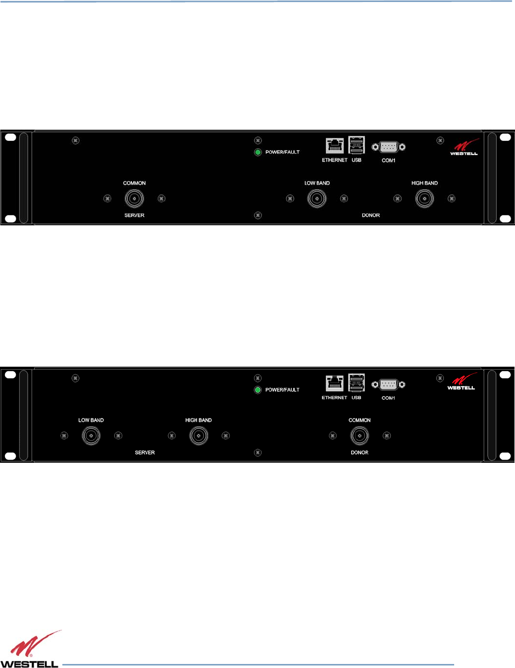
Digital Repeater Line
DSP85 Series
WESTELL.COM
© 2016 Westell Technologies 14 June 2016 Doc. No. 960-1666-MNL rJ
1.877.844.4274 Page 69 of 77
E.2 Digital Repeater Port Configurations
E.2.1
Dual-band D2:D1 Port Configuration
Input: Two single-band duplex ports, one from the low-band donor antenna and one from the high-band donor
antenna.
Output: One dual-band duplex port to the server antennas.
Figure E-9: Dual-band D2:D1 Port Configuration
E.2.2
Dual-band D1:D2 Port Configuration
Input: One dual-band duplex port from dual-band donor antenna.
Output: Two single-band duplex ports, one to the low-band server antennas and one to the high-band server
antennas.
Figure E-10: Dual-band D1:D2 Port Configuration
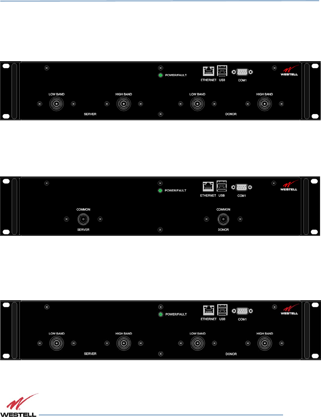
Digital Repeater Line
DSP85 Series
WESTELL.COM
© 2016 Westell Technologies 14 June 2016 Doc. No. 960-1666-MNL rJ
1.877.844.4274 Page 70 of 77
E.2.3
Dual-band D2:D2 Port Configuration
Input: Two single-band duplex ports, one from the low-band donor antenna and one from the high-band donor
antenna.
Output: Two single-band duplex ports, one to the low-band server antennas and one to the high-band server
antennas.
Figure E-11: Dual-band D2:D2 Port Configuration
E.2.4
Dual-band D1:D1 Port Configuration
Input: One dual-band duplex port from dual-band donor antenna.
Output: One dual-band duplex port to dual-band server antennas.
Figure E-12: Dual-band D1:D1 Port Configuration
E.2.5
MIMO Port Configuration
Input: Two single-band duplex ports, one from the first band donor antenna and one from the second band donor
antenna.
Output: Two single-band simplex ports, one for uplink and one for downlink.
Figure E-13: MIMO Port Configuration
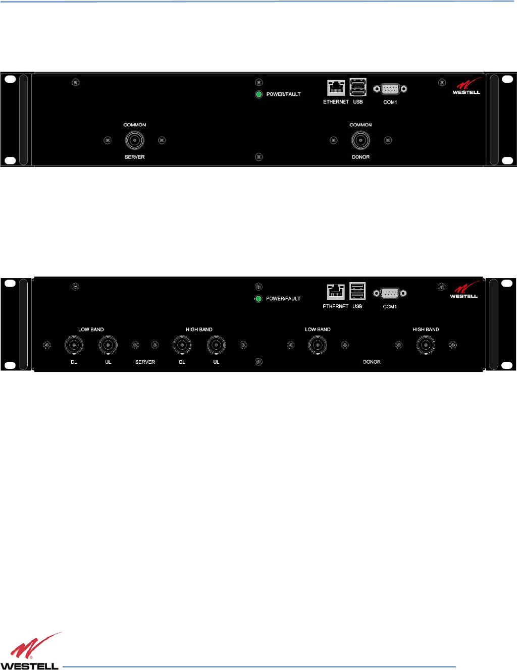
Digital Repeater Line
DSP85 Series
WESTELL.COM
© 2016 Westell Technologies 14 June 2016 Doc. No. 960-1666-MNL rJ
1.877.844.4274 Page 71 of 77
E.2.6
Single-band D1:D1 Port Configuration
Input: One single-band duplex port from donor antenna.
Output: One single-band duplex port to server antennas.
Figure E-14: Single-band D1:D1 Port Configuration
E.2.7
Dual-band D2:S4 Port Configuration
Input: Two single-band duplex ports from the donor antenna, one from the high-band, one from the low-band.
Output: Four dingle-band simplex ports, two uplink, two downlink, one uplink and one downlink for each band.
Figure E-15: Dual-band D2:S4 Port Configuration
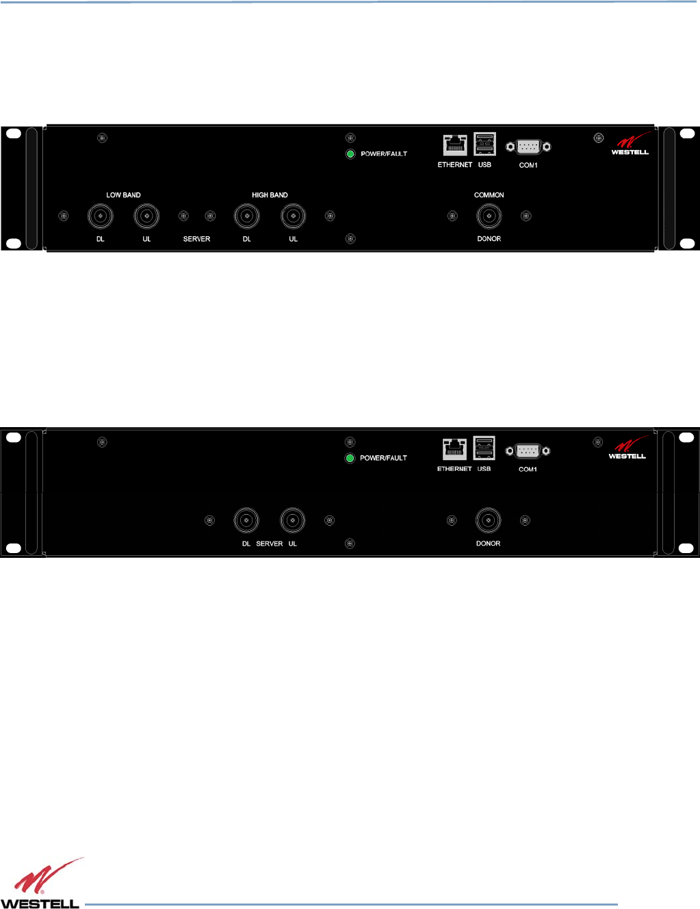
Digital Repeater Line
DSP85 Series
WESTELL.COM
© 2016 Westell Technologies 14 June 2016 Doc. No. 960-1666-MNL rJ
1.877.844.4274 Page 72 of 77
E.2.8
Dual-band D1:S4 Port Configuration
Input: One dual-band duplex port from dual-band donor antenna.
Output: Four single-band simplex ports, two uplink, two downlink, one uplink and one downlink for each band.
Figure E-16: Dual-band D1:S4 Port Configuration
E.2.9
Single-band D1:S2 Port Configuration
Input: One single-band duplex port from donor antenna.
Output: Two single-band simplex ports, one for uplink and one for downlink.
Figure E-17: Single-band D1:S2 Port Configuration
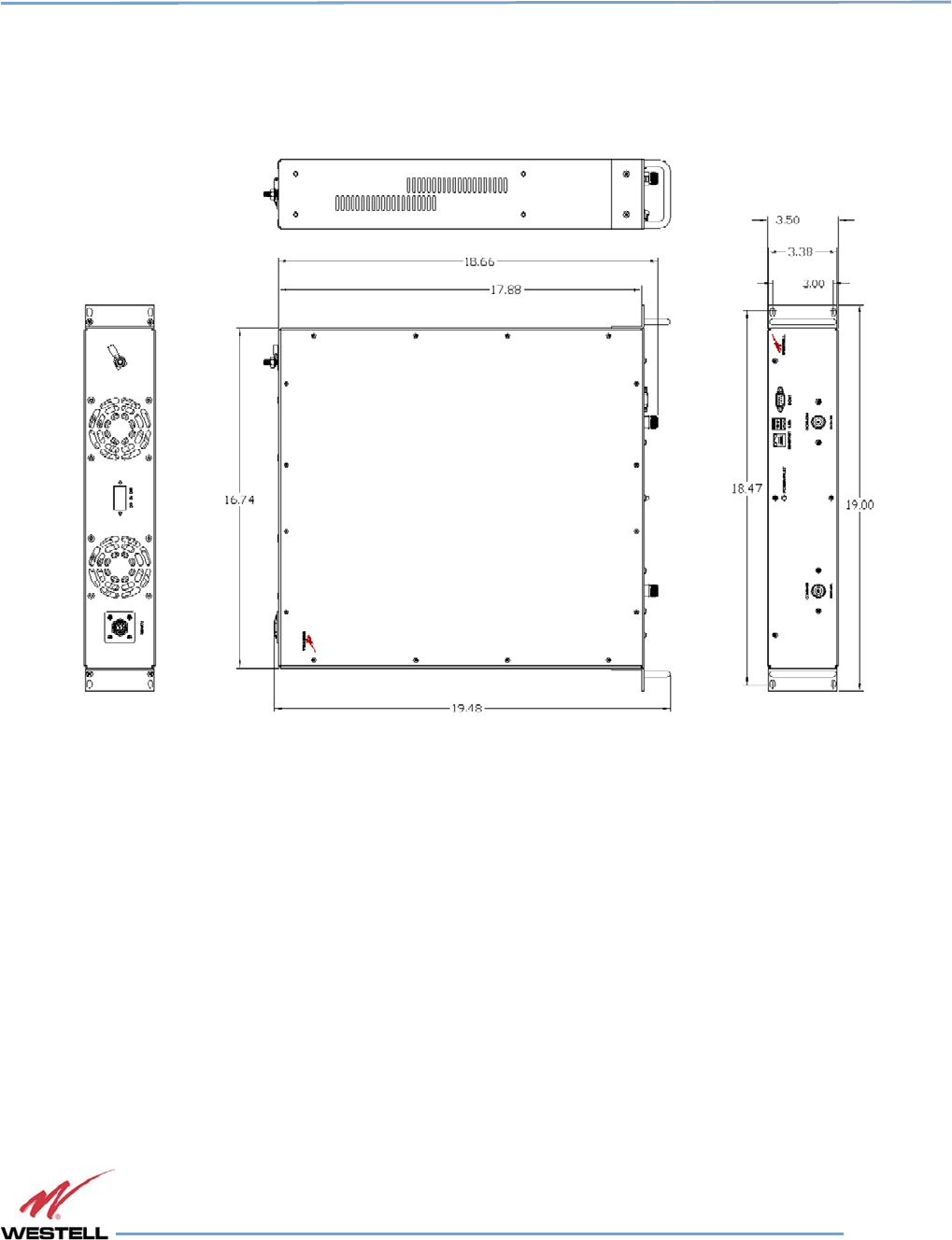
Digital Repeater Line
DSP85 Series
WESTELL.COM
© 2016 Westell Technologies 14 June 2016 Doc. No. 960-1666-MNL rJ
1.877.844.4274 Page 73 of 77
Appendix F
Mechanical Configurations
F.1 DSP85-250 and DSP85-251 Series Mechanical Drawing
Figure F-1: DSP85-250 and DSP85-251 Series Mechanical Drawing
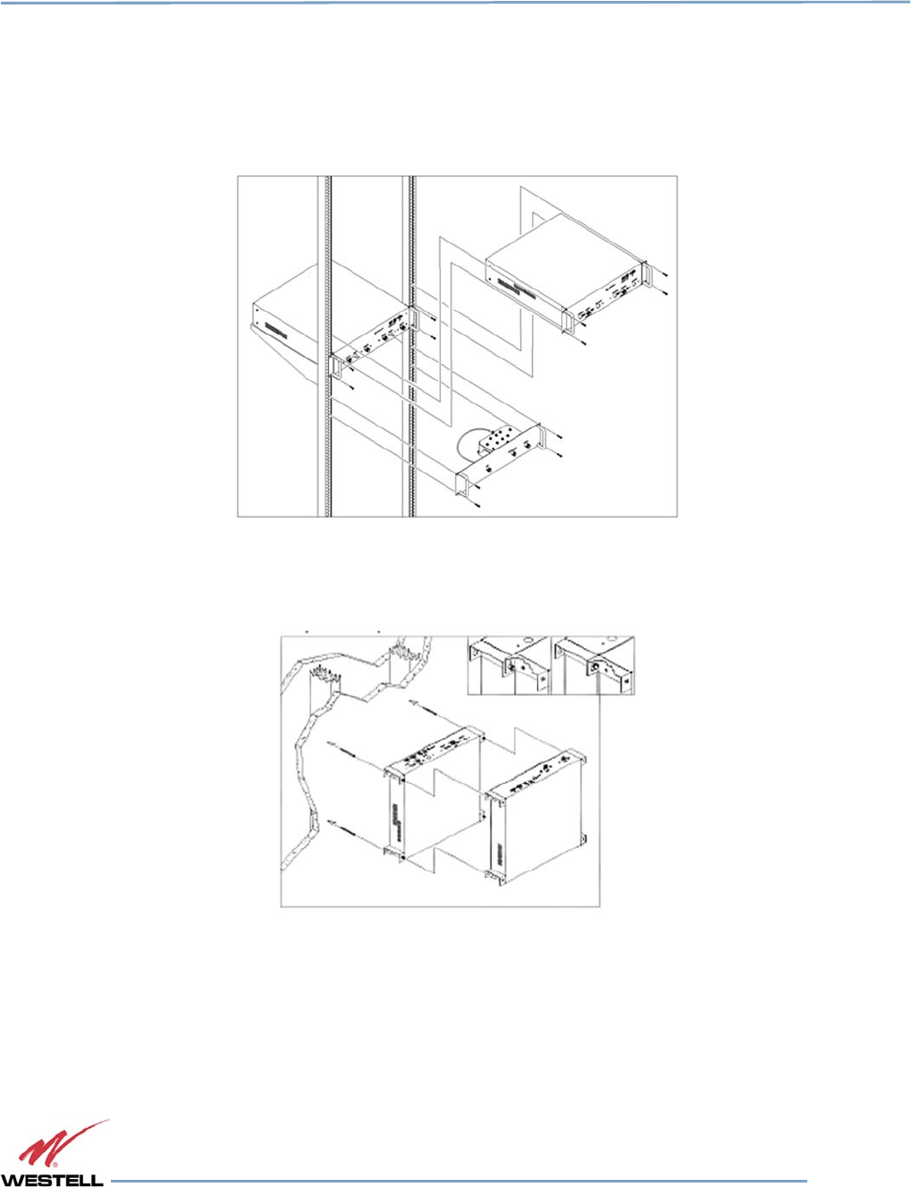
Digital Repeater Line
DSP85 Series
WESTELL.COM
© 2016 Westell Technologies 14 June 2016 Doc. No. 960-1666-MNL rJ
1.877.844.4274 Page 74 of 77
F.2 DSP85-250 and DSP85-251 Series Mounting
The following diagrams illustrate the methods for mounting the repeater(s) in a typical wall or rack installation.
Brackets are provided for both options.
Rack mounting a repeater requires two brackets mounted to the front corners of each module, Figure F-2.
Figure F-2: Rack Mounting
Wall mounting uses four brackets, one at each corner.
Figure F-3: Wall Mounting
NOTE
Westell digital repeaters must be supported in the rack system with a shelf or slide
rail. Do not rely on the brackets exclusively to support all the weight of the
modules.
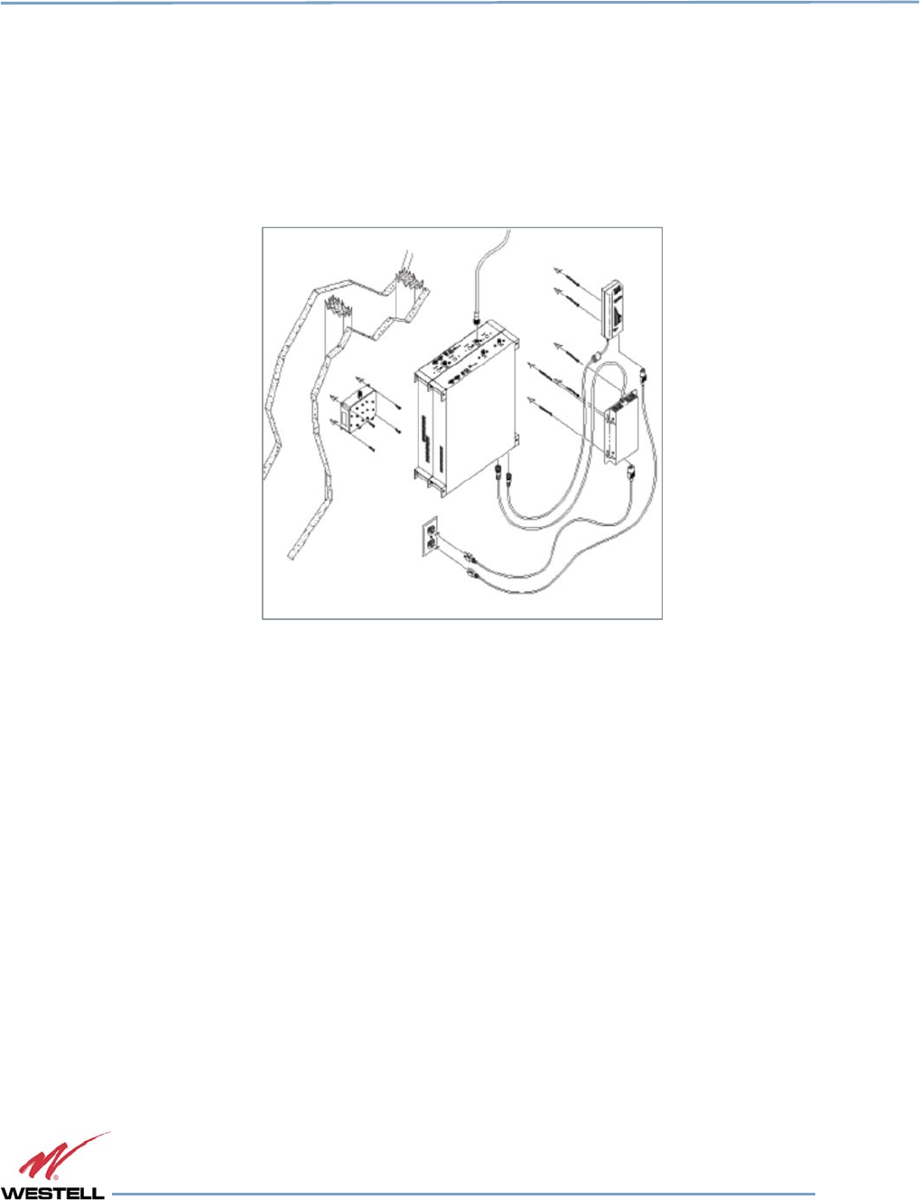
Digital Repeater Line
DSP85 Series
WESTELL.COM
© 2016 Westell Technologies 14 June 2016 Doc. No. 960-1666-MNL rJ
1.877.844.4274 Page 75 of 77
Mount the cross band coupler on the wall close enough to the repeater modules to allow the RF jumpers to reach
from the CBC to the repeaters. The attachment system used to anchor the CBC to the wall must be able to support
at least 8.4 lbs (3.8 kg).
Use a wall anchoring system for the repeaters that can support at least 42.lbs (19.05 kg) for each dual band module
and 23 lbs (10.43 kg) for each single band add on module. The power supplies are mounted approximately as
shown.
Figure F-4: System Interconnect
Interconnection of the repeaters in the rack or wall mount configuration requires the short RF jumpers supplied with
the CBC Module. The actual interconnections will depend on the bands and cross band coupler module being used.
Contact Westell’s technical support line at 1.877.844.4274 should you have questions about your specific
application.

Digital Repeater Line
DSP85 Series
WESTELL.COM
© 2016 Westell Technologies 14 June 2016 Doc. No. 960-1666-MNL rJ
1.877.844.4274 Page 76 of 77
Appendix G
Acronyms and Abbreviations
Table G-1 is a list of acronyms and abbreviations used in this manual.
Table
Table Table
Table G
GG
G-
--
-1
11
1:
: :
: Acronyms and Abbreviations
Acronyms and AbbreviationsAcronyms and Abbreviations
Acronyms and Abbreviations
Acronym/Abbreviation Definition
AGC Automatic Gain Control
APC Automatic Power Control
AUI Attachment Unit Interface
CPU Central Processing Unit
DAS Distributed Antenna System
DHCP Dynamic Host Configuration Protocol
DSP Digital Signal Processing
EEPROM Electrically Erasable Programmable Read-Only Memory
ERP Effective Radiated Power
FCS Feedback
FPGA Field Programmable Gate Array
LED Light Emitting Diode
OIP3 Third-order Intercept Point
RF Radio Frequency
SBC Single Board Computer
SNMP Simple Network Management Protocol
TMI Text Menu Interface
UHCI Universal Host Controller Interface
USB Universal Serial Bus

Digital Repeater Line
DSP85 Series
WESTELL.COM
©Westell Technologies
.
960-1666-MNL
r4