Westell PS71090-PS78 Public Safety Repeater User Manual
Westell, Inc. Public Safety Repeater
UserManual.wiki
>
Westell
>
PS71090 PS78 User Manual
User Manual
Navigation menu
Upload a User Manual
Namespaces
Wiki Guide
HTML
PDF
Info
Views
User Manual
Discussion / Help
Navigation
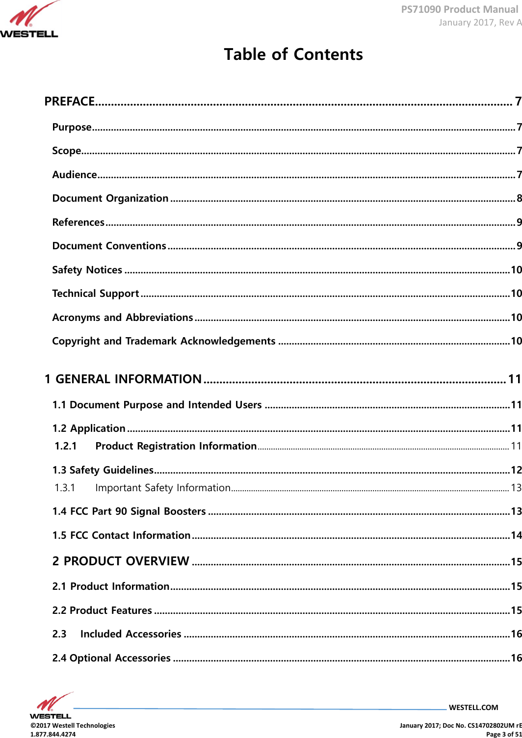
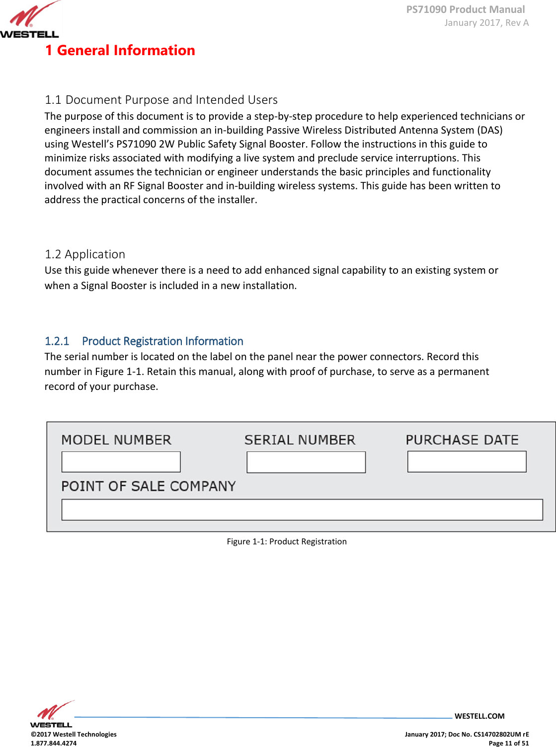
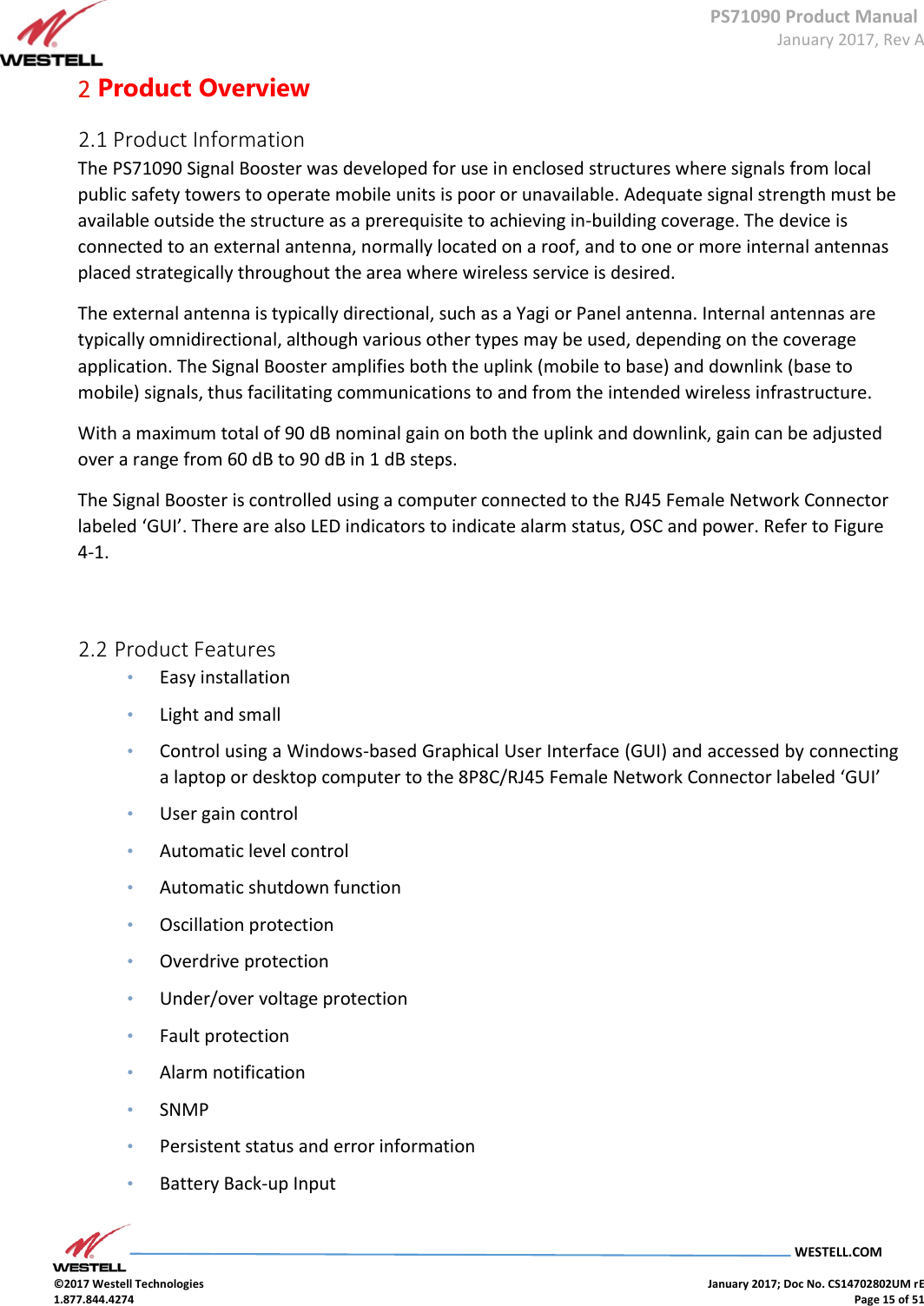
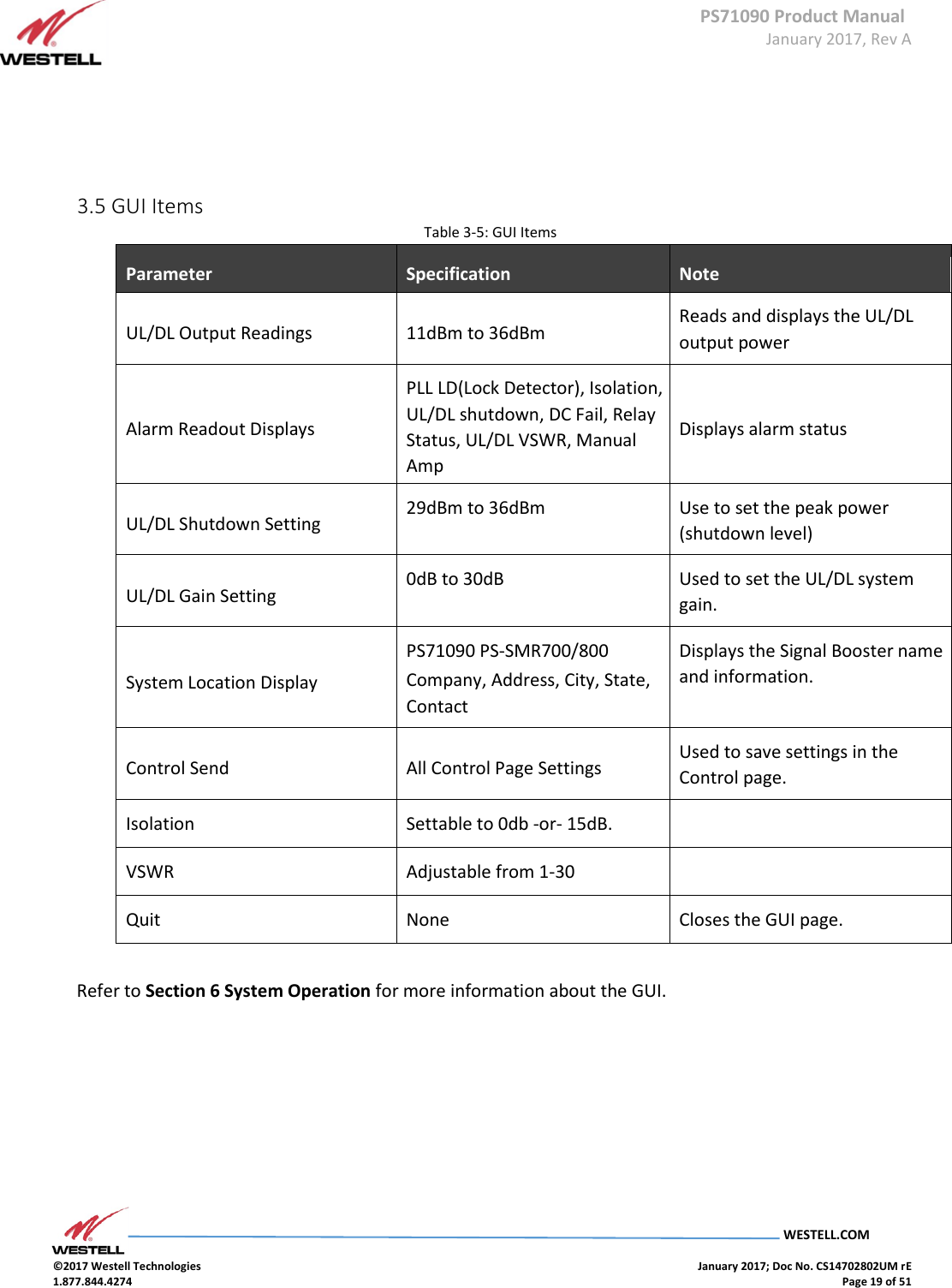
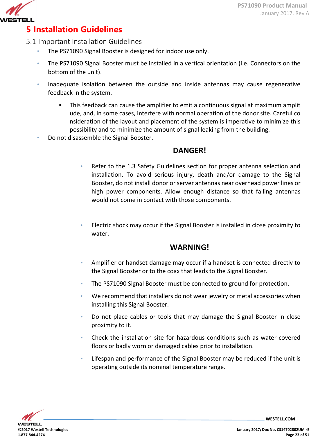
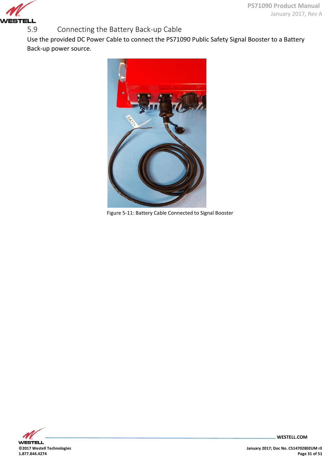
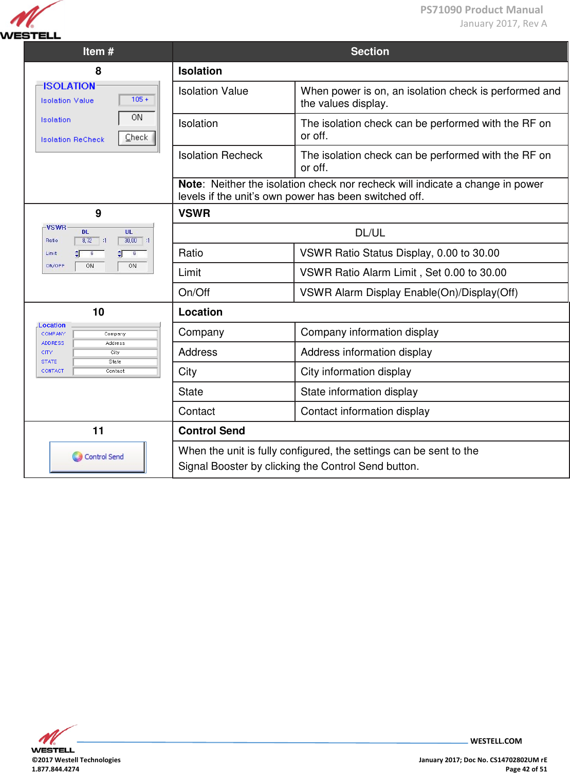
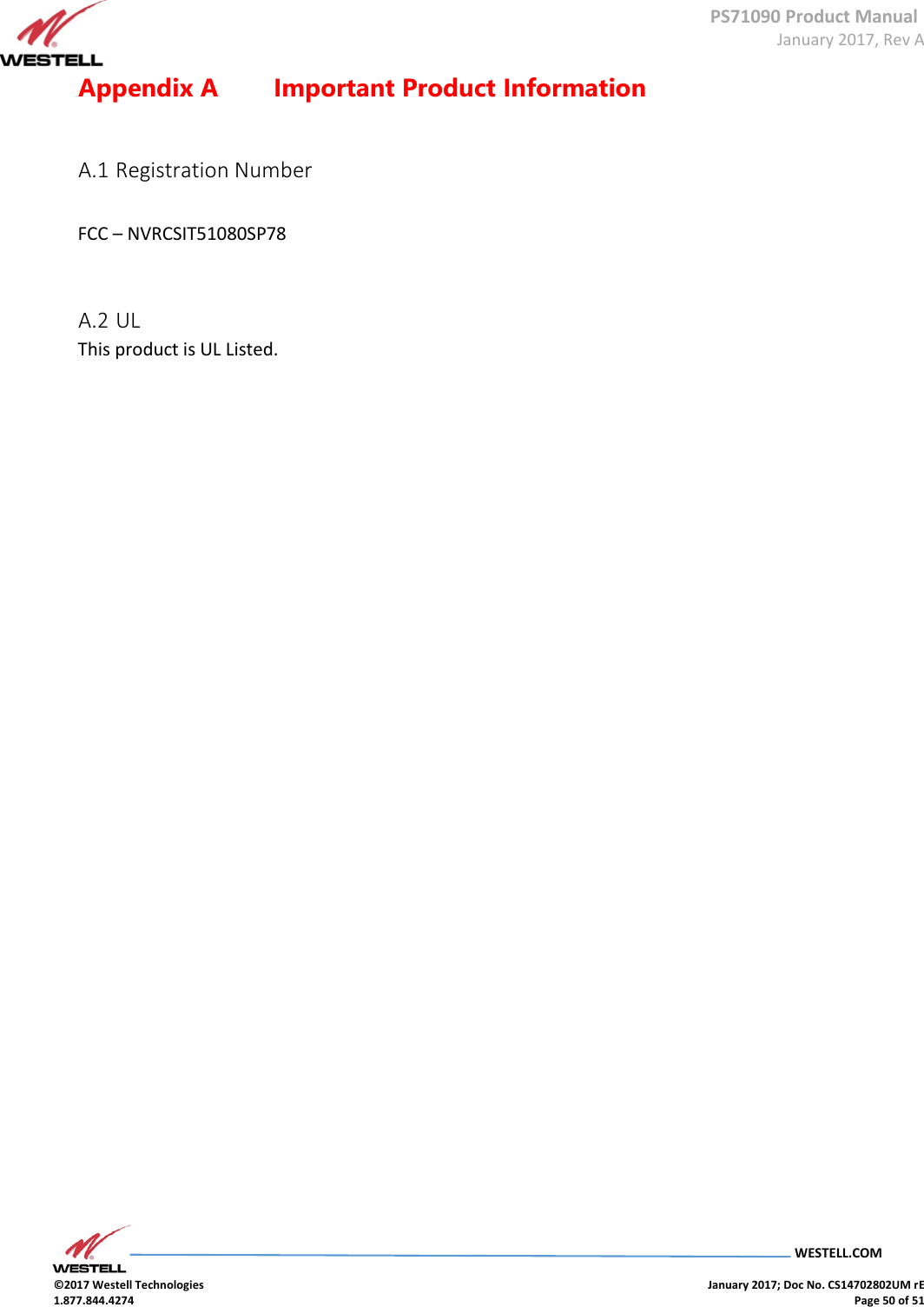
![PS71090 Product Manual January 2017, Rev A WESTELL.COM ©2017 Westell Technologies January 2017; Doc No. CS14702802UM rE 1.877.844.4274 Page 35 of 51 Item # Section 3 700 MHz Uplink Start Frequency Displays 700 MHz uplink Start frequency Stop Frequency Displays 700 MHz uplink Stop frequency Downlink Start Frequency Displays 700 MHz downlink Start frequency Stop Frequency Displays 700 MHz downlink Stop frequency 700MHz Band Allows Main-band to be set to Select 4 Downlink Gain [dB] Displays downlink gain in the 700 MHz range DL Output[dBm] Displays output level of the 700 MHz range AGC Level [dBm] Sets unit’s maximum AGC output value HPA Allows the user to toggle the downlink HPA on or off Item # Section 5 800 MHz Sub-band 1 Uplink Start Frequency Displays sub-band 1 uplink Start frequency Stop Frequency Displays sub-band 1 uplink Stop frequency Downlink Start Frequency Displays the sub-band 1 downlink start frequency Stop Frequency Displays sub-band 1 downlink Stop frequency 800MHz Band Allows sub-band 1 to be set to Select Sub-band 2 Uplink Start Frequency Displays sub-band 2 uplink Start frequency Stop Frequency Displays sub-band 2 uplink Stop frequency Downlink Start Frequency Displays sub-band 2 downlink start frequency Stop Frequency Displays sub-band 2 downlink Stop frequency 800MHz Band Allows sub-band 2 to be set to Select](https://usermanual.wiki/Westell/PS71090-PS78/User-Guide-3279429-Page-35.png)
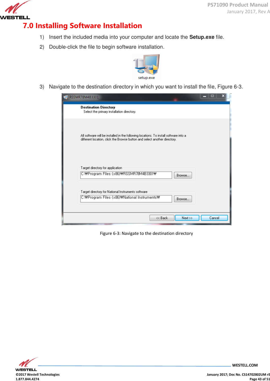
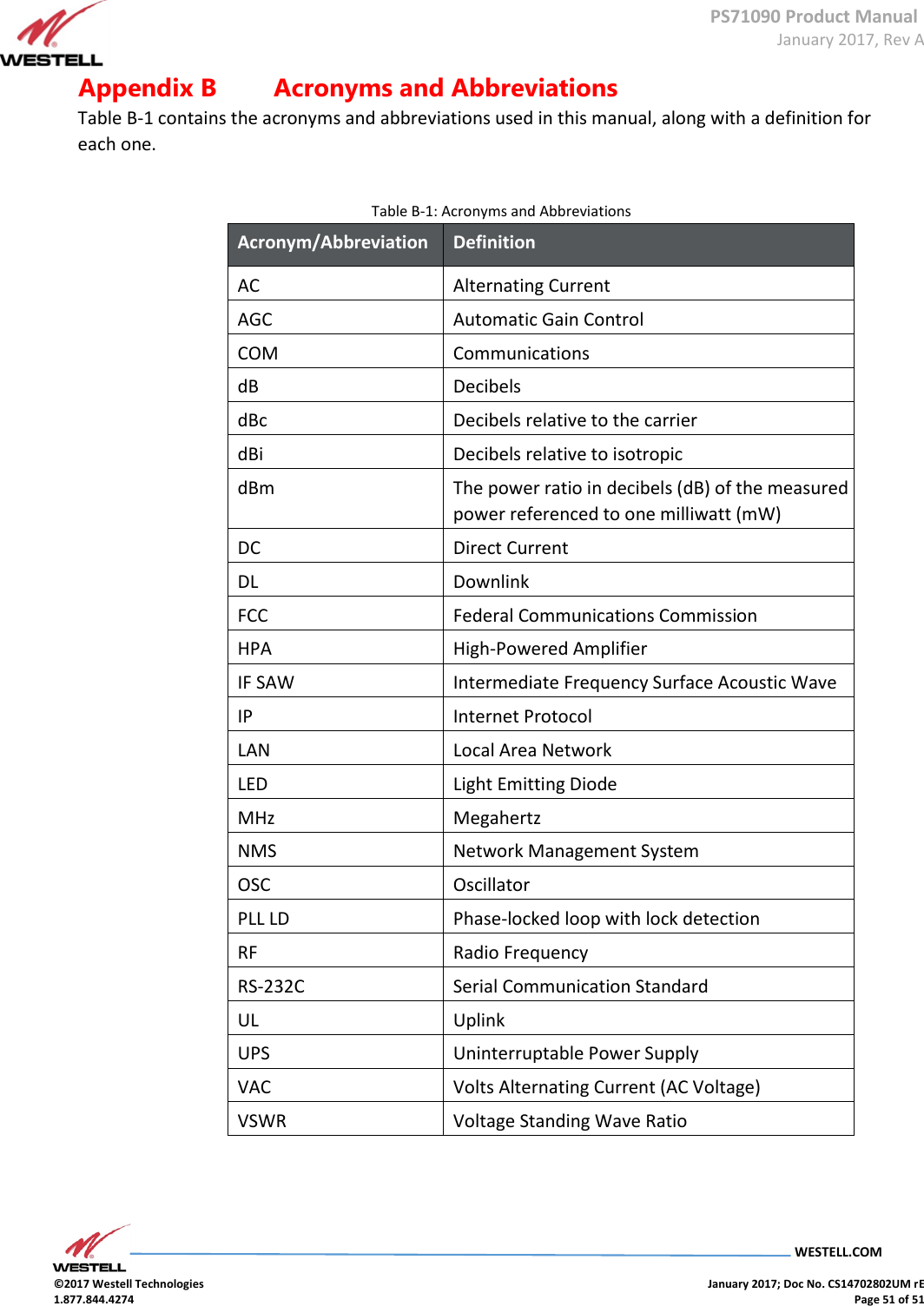
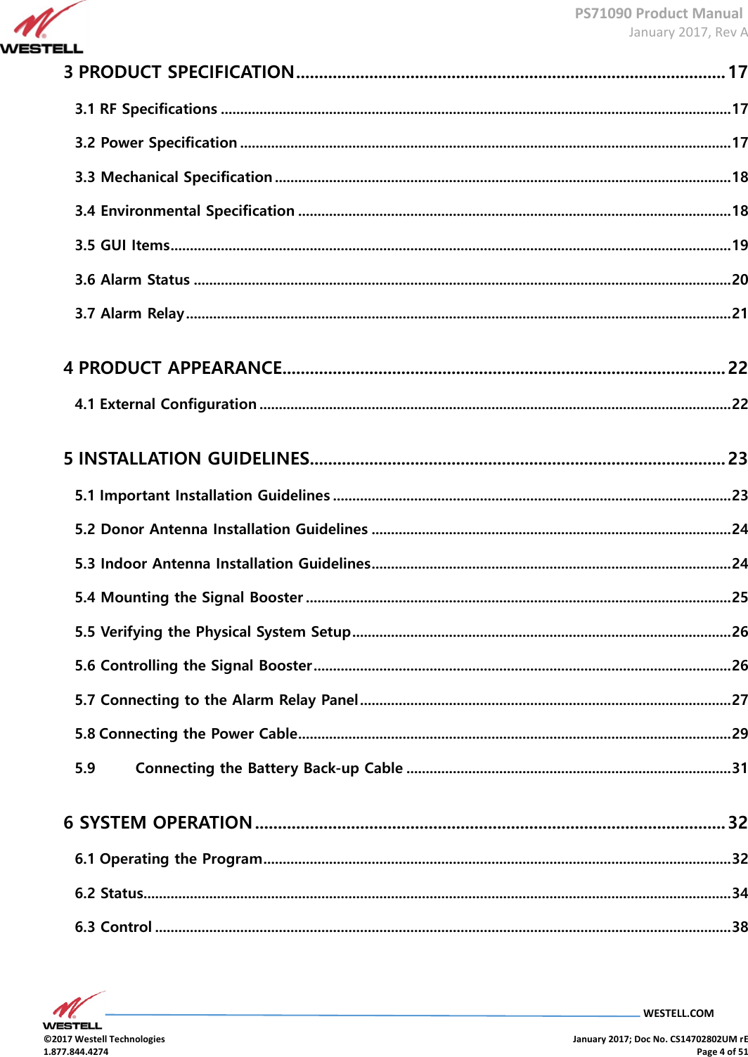
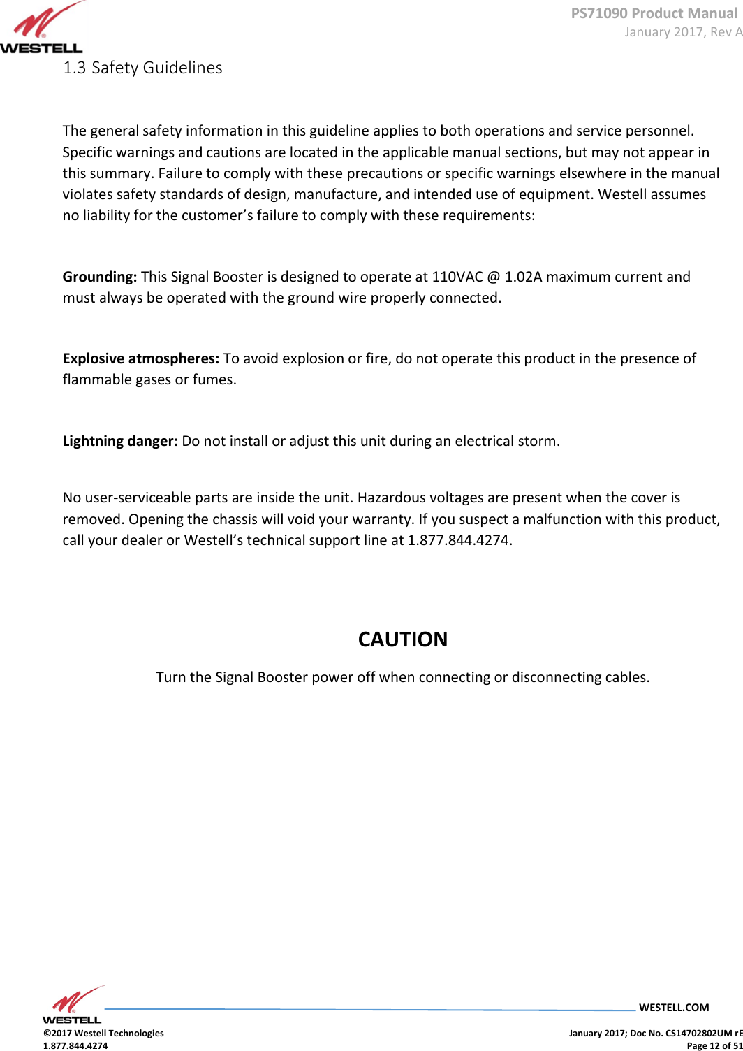
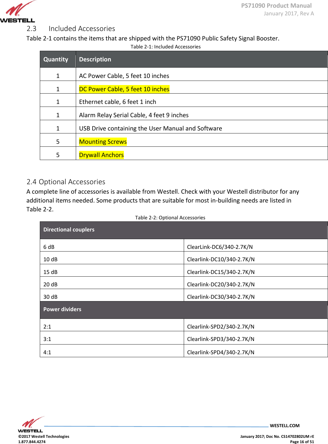
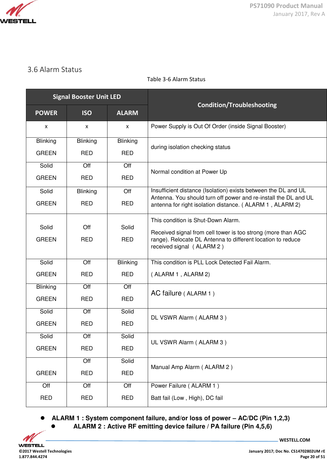
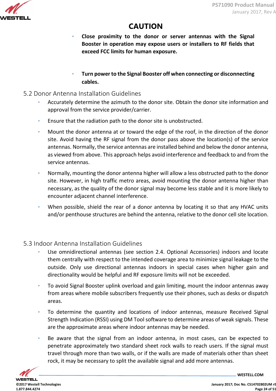
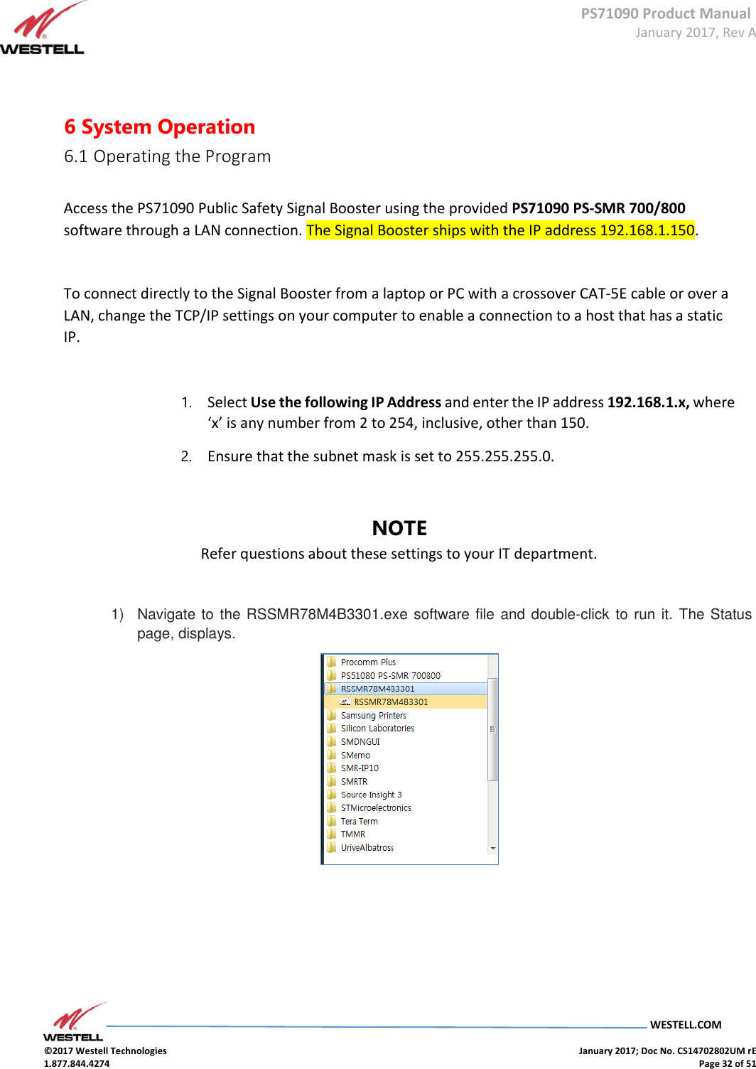
![PS71090 Product Manual January 2017, Rev A WESTELL.COM ©2017 Westell Technologies January 2017; Doc No. CS14702802UM rE 1.877.844.4274 Page 36 of 51 Item # Section 5, continued Sub-band 3 Uplink Start Frequency Displays sub-band 3 uplink Start frequency Stop Frequency Displays sub-band 3 uplink Stop frequency Downlink Start Frequency Displays sub-band 3 downlink Start frequency Stop Frequency Displays sub-band 3 downlink Stop frequency 800MHz Band Allows sub-band 3 to be set to Select 6 Uplink 700 & 800 MHz Gain (dB) Displays status of the uplink gain UL Output [dBm] Displays uplink output level ALC Level [dBm] Sets the unit’s maximum ALC output value HPA Allows the user to toggle the uplink high power amplifier on or off 7 Isolation Isolation Value When power is on, an isolation check is performed and the values are displayed Isolation The isolation check can be performed with the RF on or off Note: Neither the isolation check, nor recheck, will indicate a change in power levels if the unit’s own power has been switched off. Item # Section 8 Alarm Status Not User-Configurable/Informational Only ( GREEN = Normal; RED = Alarm ) PLL LD Display alarm Isolation Display alarm Shutdown (DL/UL) Display alarm DC Fail Display alarm Relay Status Display alarm DL VSWR DL Path VSWR check UL VSWR UL Path VSWR check Manual Amp User HPA OFF Alarm BATT FAIL (LOW) BATT Low Power Alarm BATT FAIL (HIGH) BATT High Power Alarm](https://usermanual.wiki/Westell/PS71090-PS78/User-Guide-3279429-Page-36.png)
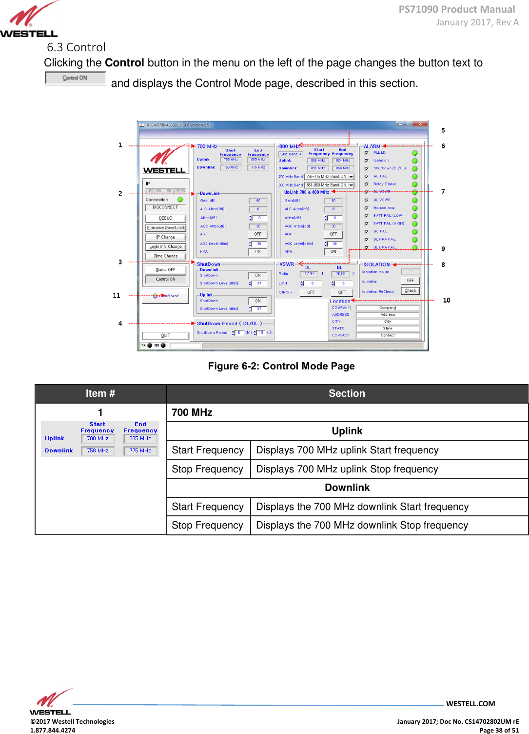
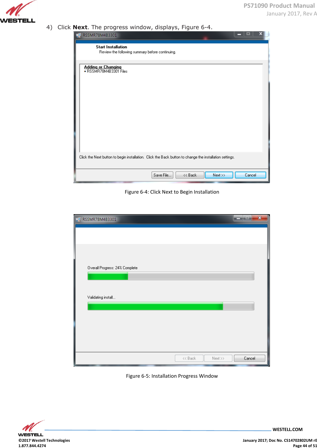
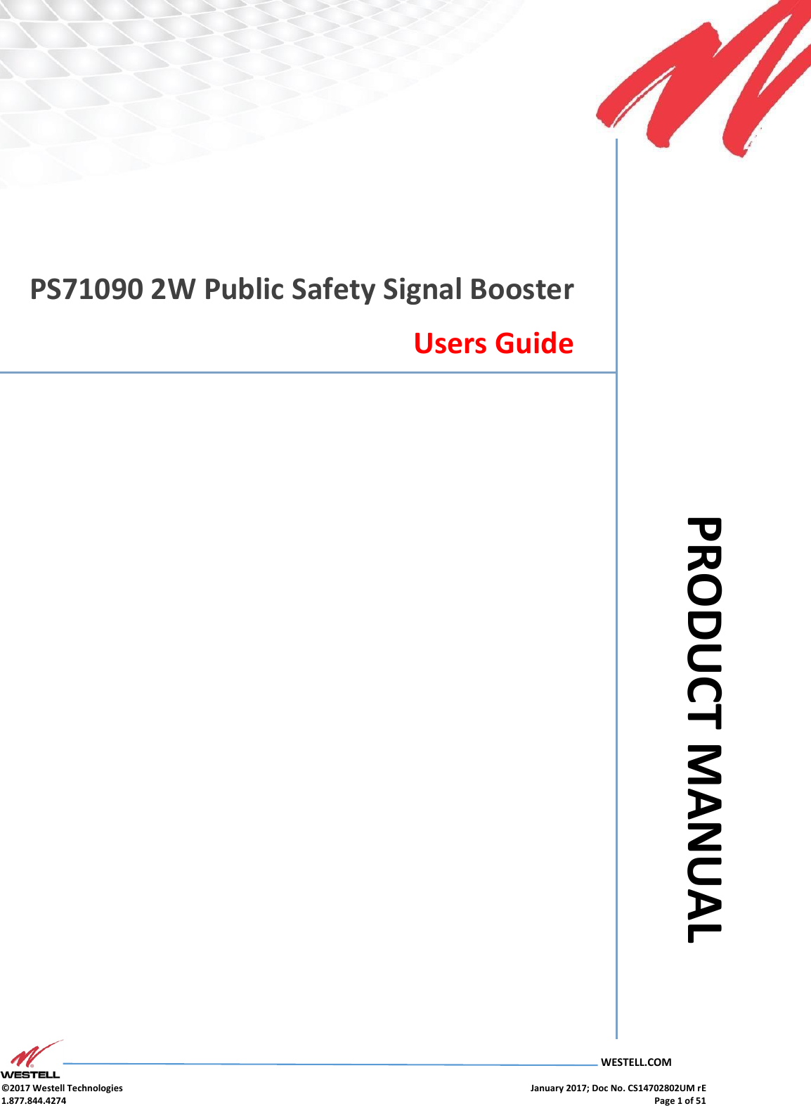
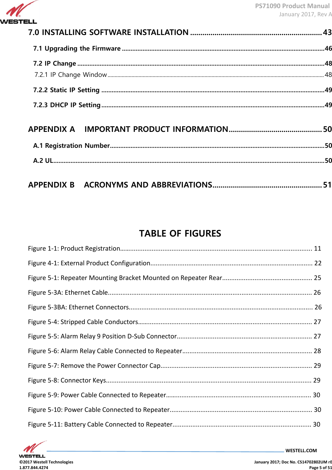
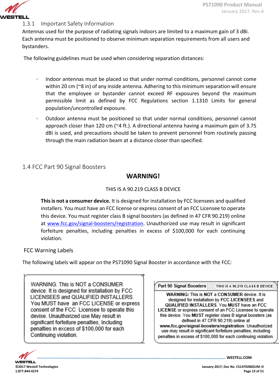
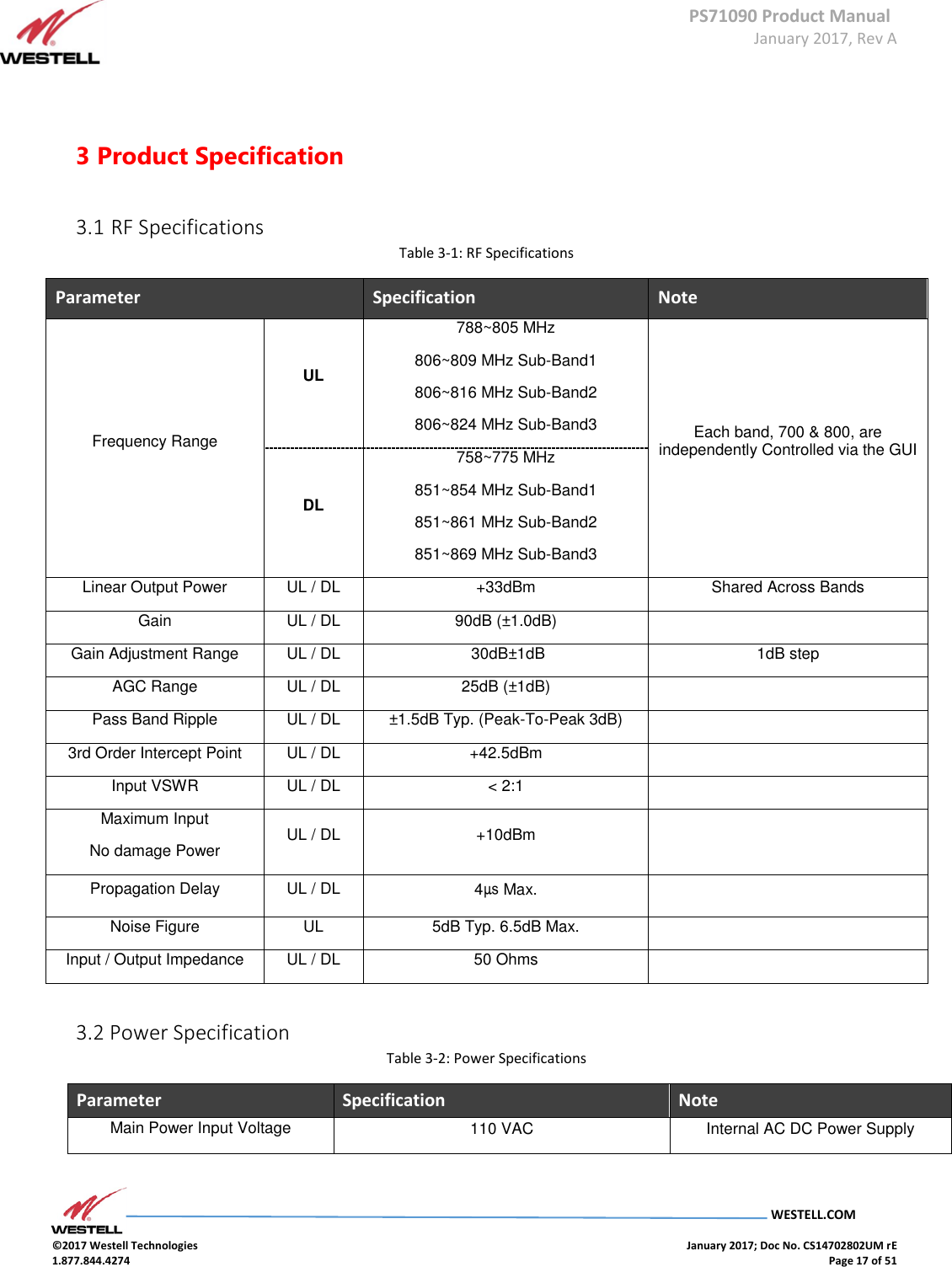
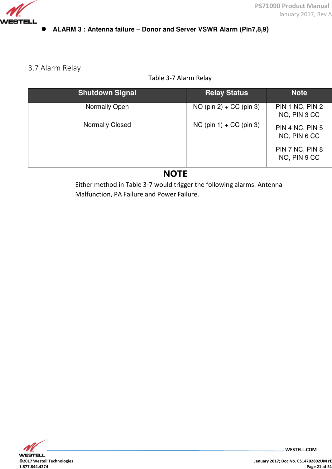
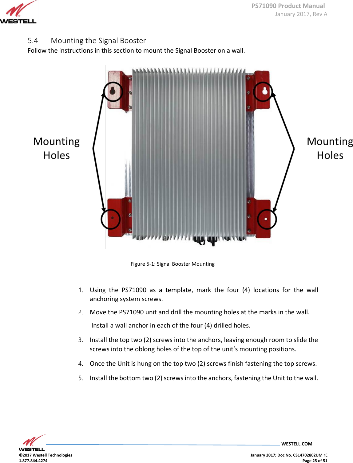
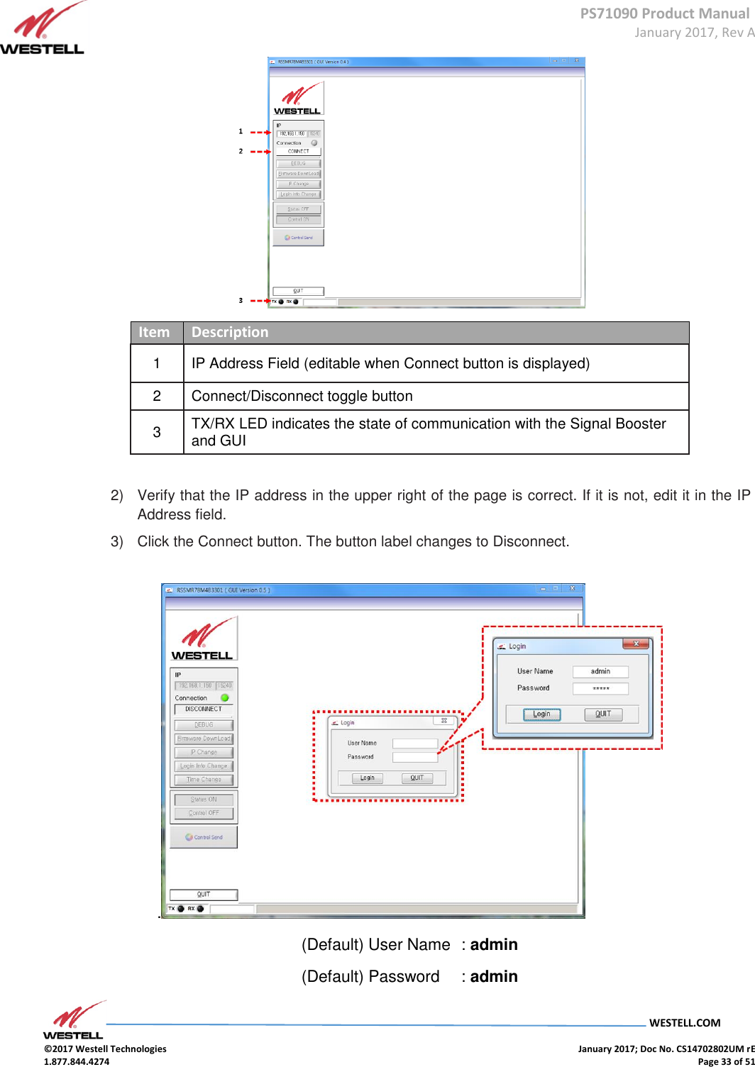
![PS71090 Product Manual January 2017, Rev A WESTELL.COM ©2017 Westell Technologies January 2017; Doc No. CS14702802UM rE 1.877.844.4274 Page 39 of 51 Item # Section 2 Downlink Gain [dB] Displays downlink gain in the 700 MHz range ALC Atten [dB] Displays attenuation value by ALC Atten [dB] Displays attenuation value controlled by down link AGC Atten [dB] Displays attenuation value controlled by AGC AGC Control Auto Level Control Function On/Off AGC Level [dBm] Sets the unit’s maximum ALC output value HPA Down link HPA On/Off 3 Shutdown Allows the shut-down level to be set Downlink Shutdown Allows the downlink shutdown level to be set to on or off. Shutdown Level [dBm] Allows the maximum shutdown level to be set between 23 and 37 Uplink Shutdown Allows the uplink shut down level to be set to on or off Shutdown Level [dBm] Allows the maximum shutdown level to be set between 23 and 37 4 Shutdown Period Allows the shutdown period to be set Shutdown Period Allows the shutdown period to be set in minutes and seconds. Item # Section 5 800 MHz Sub-band 1 Uplink Start Frequency Displays sub-band 1 uplink Start frequency Stop Frequency Displays sub-band 1 uplink Stop frequency Downlink Start Frequency Displays sub-band 1 downlink Start frequency Stop Frequency Displays sub-band 1 downlink Stop frequency 800 MHz Band Allows sub-band 1 to be set to Select Sub-band 2 Uplink Start Frequency Displays sub-band 2 uplink start frequency](https://usermanual.wiki/Westell/PS71090-PS78/User-Guide-3279429-Page-39.png)
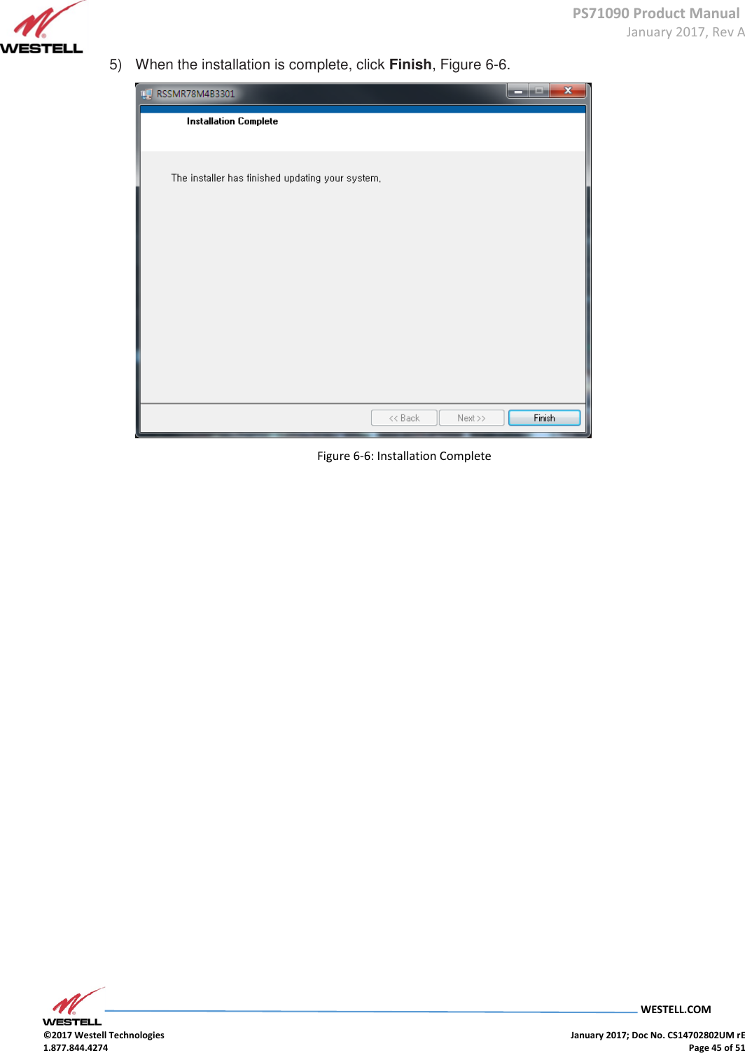
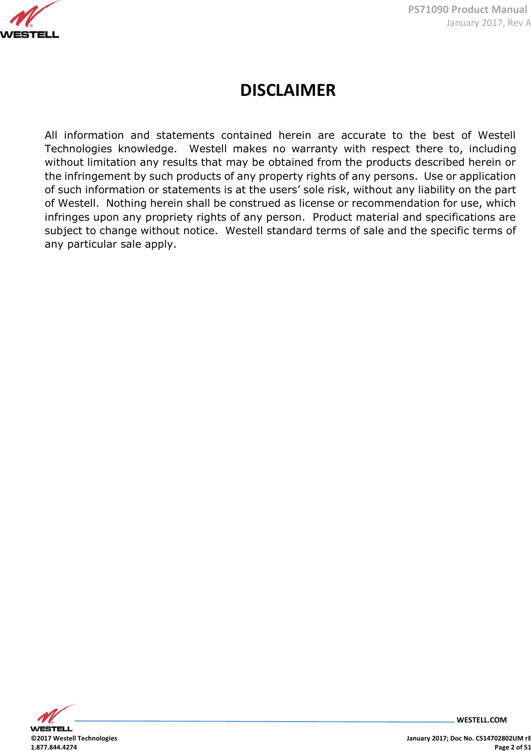
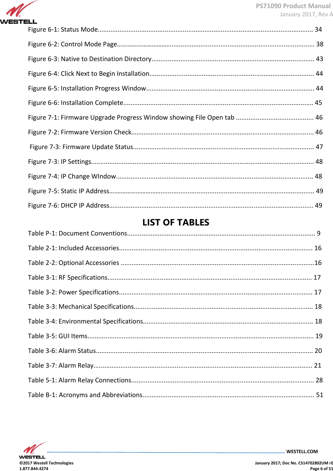
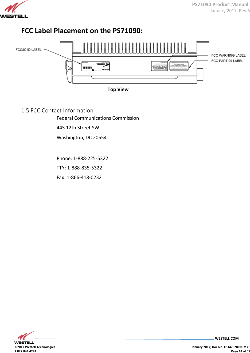
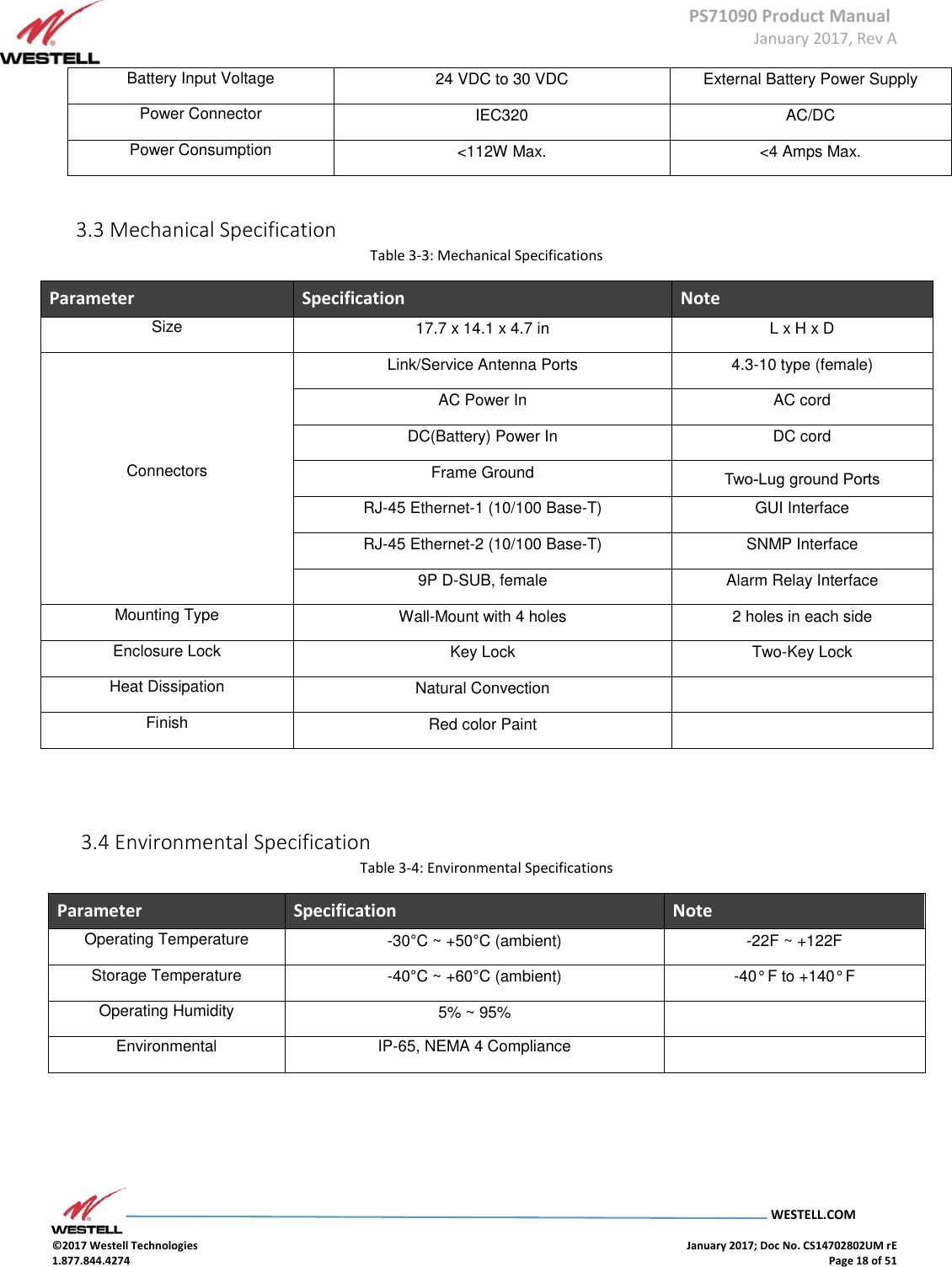
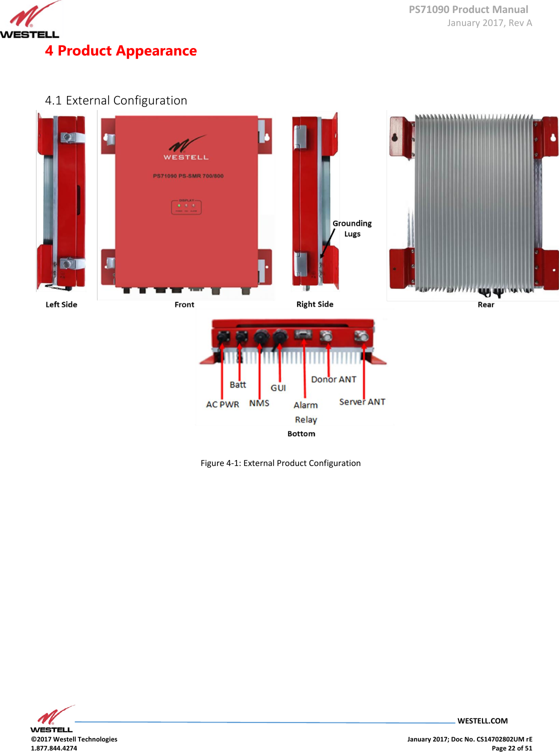
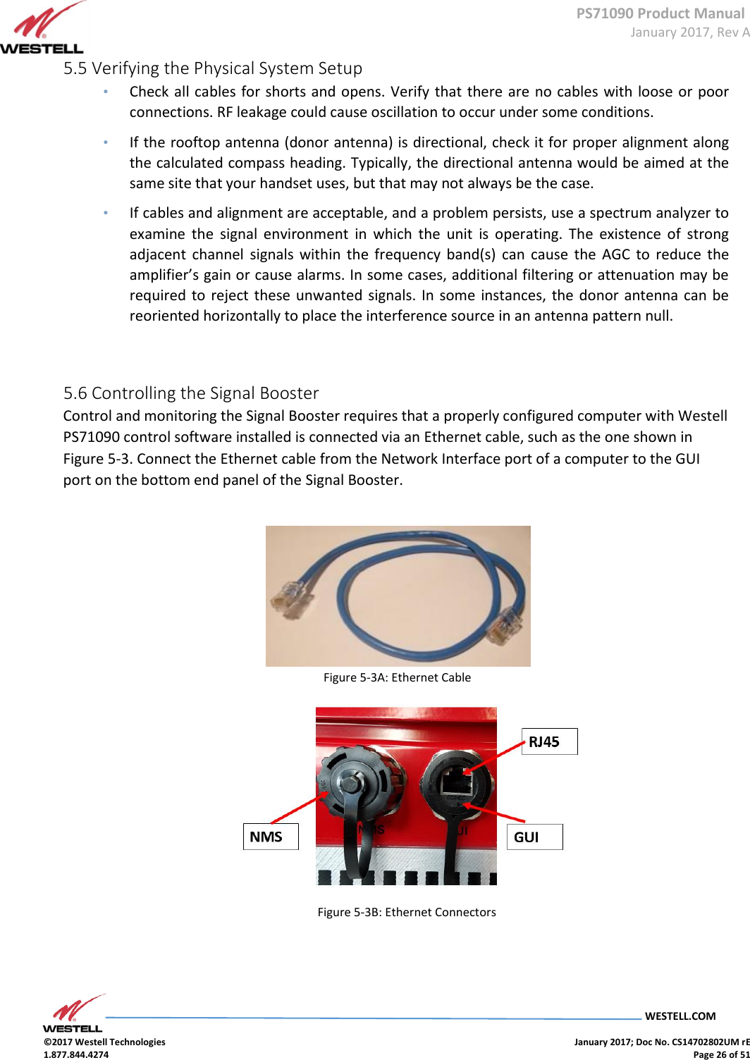
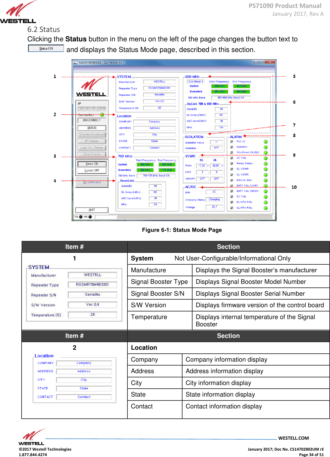
![PS71090 Product Manual January 2017, Rev A WESTELL.COM ©2017 Westell Technologies January 2017; Doc No. CS14702802UM rE 1.877.844.4274 Page 40 of 51 Item # Section 2 Downlink Gain [dB] Displays downlink gain in the 700 MHz range ALC Atten [dB] Displays attenuation value by ALC Atten [dB] Displays attenuation value controlled by down link AGC Atten [dB] Displays attenuation value controlled by AGC AGC Control Auto Level Control Function On/Off AGC Level [dBm] Sets the unit’s maximum ALC output value HPA Down link HPA On/Off End Frequency Displays the sub-band 2 uplink end frequency Downlink Start Frequency Displays sub-band 2 downlink Start frequency Stop Frequency Displays sub-band 2 downlink Stop frequency 800 MHz Band Allows sub-band 2 to be set to Select Item # Section 5, continued Sub-band 3 Uplink Start Frequency Displays sub-band 3 uplink Start frequency Stop Frequency Displays sub-band 3 uplink Stop frequency Downlink Start Frequency Displays sub-band 3 downlink start frequency Stop Frequency Displays sub-band 3 downlink Stop frequency 800 MHz Band Allows sub-band 3 to be set to Select Uplink 700 & 800 MHz 700 MHz Band Drop-Down Allows selection to turn the 758-775 MHz band on or off 800 MHz Band Drop-Down Allows selection to turn the 851-854 MHz Band on or off Allows selection to turn the 851-861 MHz Band on or off Allows selection to turn the 851-869 MHz Band on or off 5, continued](https://usermanual.wiki/Westell/PS71090-PS78/User-Guide-3279429-Page-40.png)
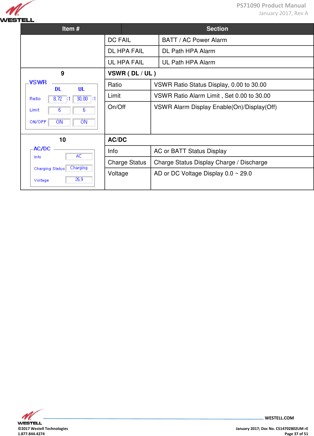
![PS71090 Product Manual January 2017, Rev A WESTELL.COM ©2017 Westell Technologies January 2017; Doc No. CS14702802UM rE 1.877.844.4274 Page 41 of 51 Item # Section 6 Gain (dB) Displays status of the uplink gain ALC Atten [dB] Displays attenuation value controlled by ALC Atten [dB] Sets the attenuation value AGC Atten [dB] Displays attenuation value controlled by AGC AGC Control Auto Gain Control Function On/Off AGC Level [dBm] Sets the unit’s maximum AGC output value HPA Uplink HPA On/Off 7 Alarm ( GREEN = Normal; RED = Alarm ) PLL LD Displays alarm Isolation Displays alarm Shutdown (DL/UL) Displays alarm DC Fail Displays alarm Relay Status Displays alarm DL VSWR DL Path VSWR check UL VSWR UL Path VSWR check Manual Amp User HPA OFF Alarm BATT FAIL (LOW) BATT Low Power Alarm BATT FAIL (HIGH) BATT High Power Alarm DC FAIL BATT / AC Power Alarm DL HPA FAIL DL Path HPA Alarm UL HPA FAIL UL Path HPA Alarm](https://usermanual.wiki/Westell/PS71090-PS78/User-Guide-3279429-Page-41.png)