Westell PSA41080-VHF Bi-Directional Amplifier User Manual Part 3
Westell, Inc. Bi-Directional Amplifier Part 3
Westell >
Contents
- 1. User Manual_Part 1
- 2. User Manual_Part 2
- 3. User Manual_Part 3
User Manual_Part 3
VHF Product Manual
July 2018, Rev B
WESTELL.COM
©2017 Westell Technologies July 2018; Doc No. VHF Signal Booster UM RA
1.877.844.4274 Page 72 of 95
Firmware selection
(only for dual
version)
User can change filtering mode in case of dual version
signal booster
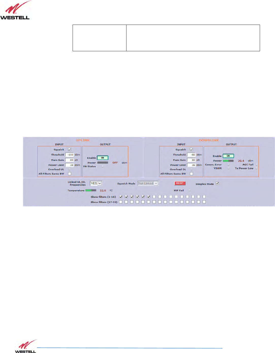
Simplex mode checkbox control is only visible in devices with such capability. It allows signal
flow only in one direction, either uplink or downlink, at any given time. The chosen direction is
made automatically based on signal detection which, in turn, depends on squelch. Therefore,
turning on simplex mode automatically turns on squelch, both in uplink and downlink sections,
and disables these controls for the user. Besides, it also sets squelch mode to "Not Linked" and
disables this control, too. This is necessary since otherwise the lack of RF input signal in downlink
would mute the uplink RF input, thus blocking all communication. The look of the general
control frame in simplex mode is as in next image:
Filter control frame for narrow-band version
• Filtering control frame.
VHF Product Manual
July 2018, Rev B
WESTELL.COM
©2017 Westell Technologies July 2018; Doc No. VHF Signal Booster UM RA
1.877.844.4274 Page 73 of 95
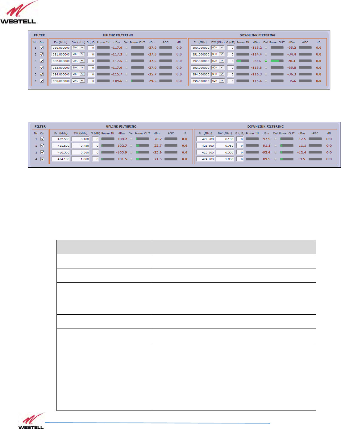
Filter control frame for narrow-band version
Filter control frame for adjustable bandwidth version
• Filter control frame: shows configuration and monitoring information of all filters. The
frame is divided in two: uplink and downlink. Data showed in each half is symmetric.
Filter control frame
Parameter
Description
On
Allows to enable/disable each filter
Frequency
Configures center frequency of each filter
Bandwidth filter control for
narrow-band version only
There are up to five available filters (depending on
factory setup) to adjust the trade-off between rejection
to undesired signals and delay
Fine gain control
Each channel gain can be fine adjusted
RF input pow
er
Shows RF input level for each channel
Signal detection
With this indicator, system shows if signal is detected at
input, according to squelch threshold. Moreover, with
Squelch Mode = ‘Linked’, UL shows no signal if signal is
not detected in the same DL channel even if UL signal
exceed squelch threshold. Similarly, with simplex mode
enabled, if one signal is detected at DL band, all UL
filters will show “No signal”

VHF Product Manual
July 2018, Rev B
WESTELL.COM
©2017 Westell Technologies July 2018; Doc No. VHF Signal Booster UM RA
1.877.844.4274 Page 74 of 95
RF output power
Shows estimation for RF output level for each channel,
according to programmed gain and AGC control. Shows
‘OFF’ in the same cases that signal detection shows ‘No
signal’
AGC
Indicates gain reduction due to power limitation control.
In case of adjustable filter version, filter control frame is slightly different. According to
entry mode button, frequency and bandwidth parameter configuration can be:
o Center frequency (in 25KHz steps) and bandwidth filters (50KHz steps)
o Start and stop frequencies (in 25KHz steps)
VHF Product Manual
July 2018, Rev B
WESTELL.COM
©2017 Westell Technologies July 2018; Doc No. VHF Signal Booster UM RA
1.877.844.4274 Page 75 of 95
12
1212
12
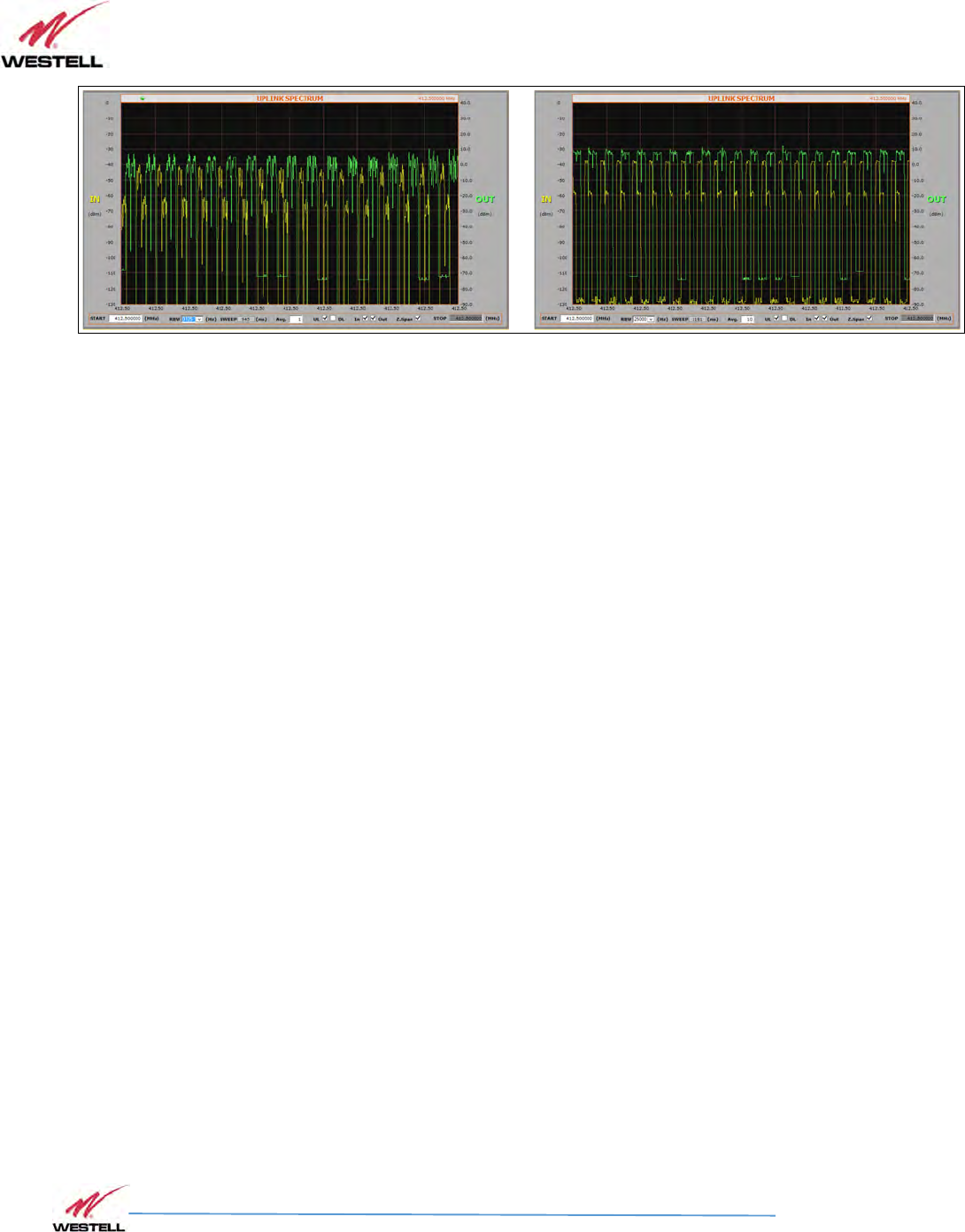
Spectrum Analyzer
Spectrum AnalyzerSpectrum Analyzer
Spectrum Analyzer
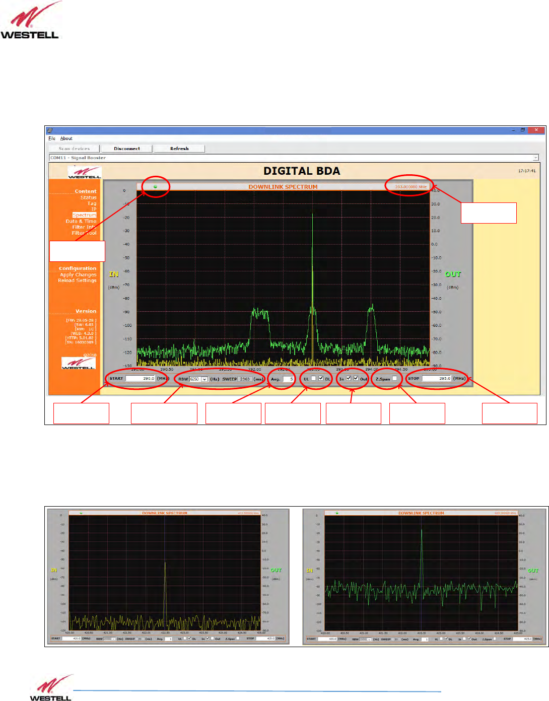
The spectrum analyzer feature of the Signal Booster is a useful tool for
commissioning and troubleshooting. This section explains how to use it.
Frequency at
cursor position
Stop frequency
setting
Stop frequency
setting
Scan refresh
indication
Resolution bandwidth &
Sweep time readout Zero Span switch
Input & Output
trace enable
Uplink / Downlink
switch
Uplink / Downlink
switch
Spectrum analyzer settings
Input and output signals are scanned successively and can be shown or hidden
independently:
Spectrum input/output selection
VHF Product Manual
July 2018, Rev B
WESTELL.COM
©2017 Westell Technologies July 2018; Doc No. VHF Signal Booster UM RA
1.877.844.4274 Page 76 of 95
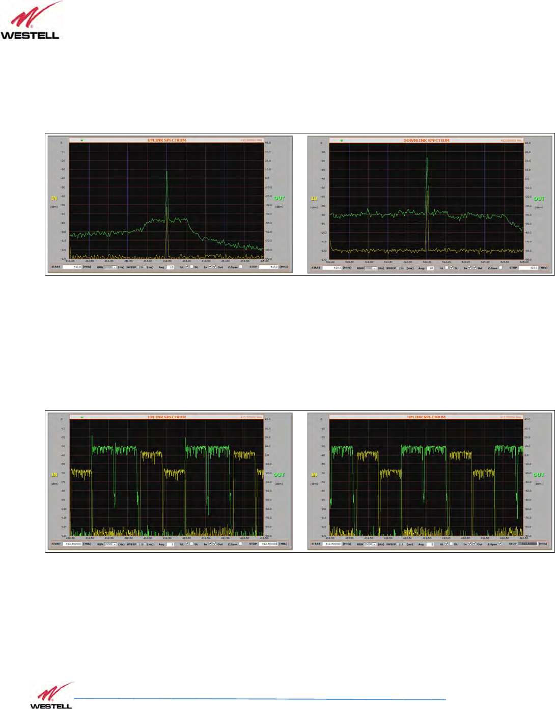
Either uplink or downlink signal paths are chosen and average up to 32 can help to clean
noise signals. Resolution bandwidth and sweep time are set automatically.
Spectrum UL / DL selection
When start and stop frequencies are set equal, then zero-span mode is activated to show
evolution of signals with time, which may be of special interest with pulsed signals. The
same thing can be achieved by setting the zero-span checkbox, with the convenience that
start frequency change would also change stop frequency accordingly.
Spectrum zero-span mode
Resolution bandwidth becomes enabled in zero-span mode and sweep time is
automatically set according to its setting, which is user selectable between 25.000Hz,
12.500Hz, 6.250Hz and 3.125Hz. Average setting will also impact sweep time in a similar
way.
VHF Product Manual
July 2018, Rev B
WESTELL.COM
©2017 Westell Technologies July 2018; Doc No. VHF Signal Booster UM RA
1.877.844.4274 Page 77 of 95
Zero span settings
VHF Product Manual
July 2018, Rev B
WESTELL.COM
©2017 Westell Technologies July 2018; Doc No. VHF Signal Booster UM RA
1.877.844.4274 Page 78 of 95
13
1313
13
SNMP Agent
SNMP AgentSNMP Agent
SNMP Agent
Westell Signal Booster includes a SNMPv1 agent that allows user to supervise the device by
means of 'SET' and 'GET' type commands and, asynchronous traps to notify alarm conditions
can be sent. The device is intended to be monitored by a polling NMS but it can send traps to a
NMS or Trap Receiver if enabled. Westell can provide a NMS system upon request.
The following sections will show the user configurable, relevant information that can be read
via SNMP from the device. The tables will describe these values in order to explain how the
information has to be read and interpreted.
MIB Description
The associated MIB document is WESTELL-BDA-SYSTEMv13-MIB.mib. The Westell MIB is
divided into blocks. Each block describes the characteristics and values of a specific element
but not all elements are implemented in this agent. Each MIB block is divided in two segments,
named 1T and 2T. Segment 1T contains the information that is fixed & read only. Segment 2T
has the information that can vary over time, regardless of it being read/only or read/write.
The following sections will show the user configurable, relevant information that can be read
via SNMP from the device.
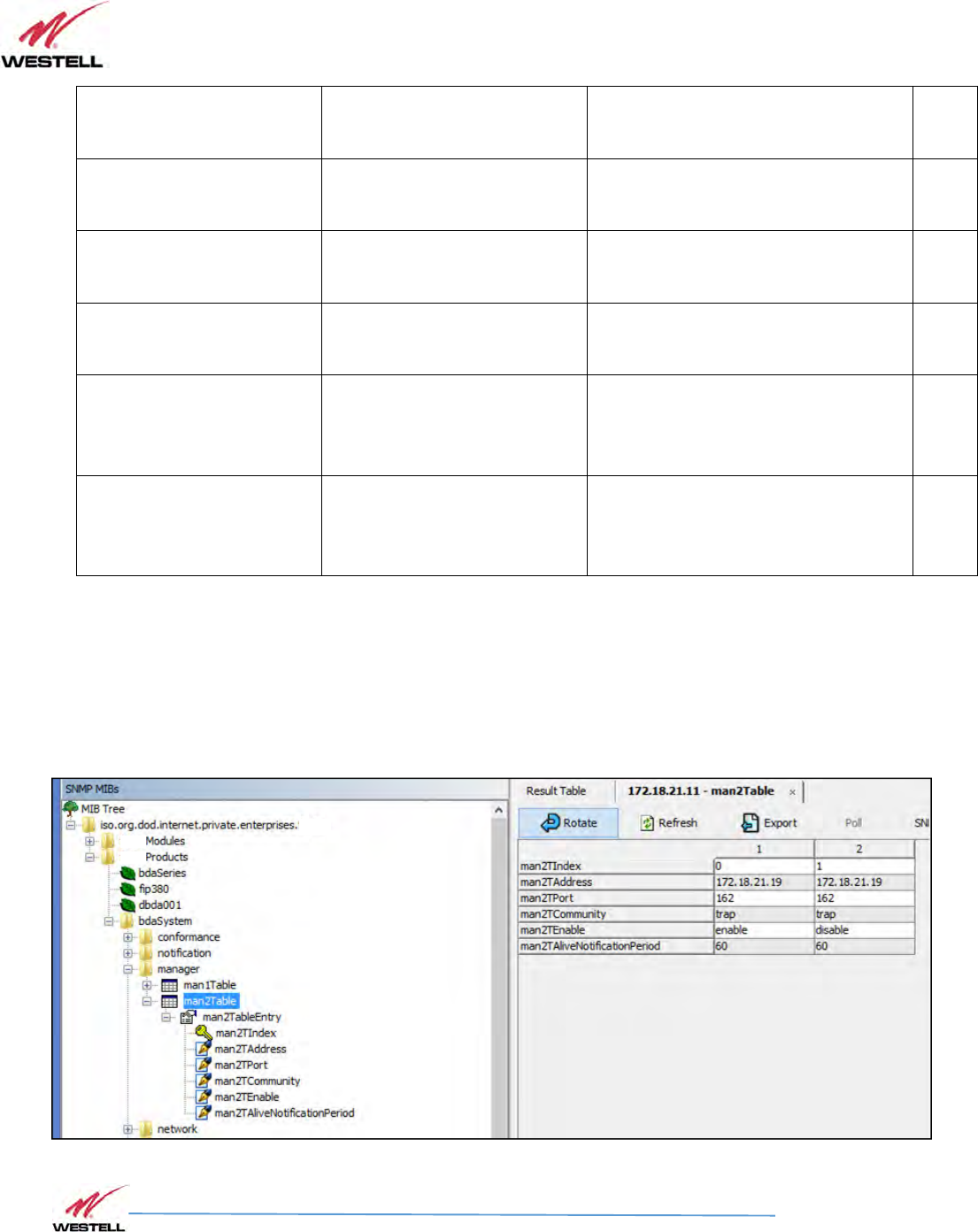
Manager
This is a table with 2 consecutive elements, one for each NMS. No checking is done of the
validity of the information stored in the table, so extra care must be taken by the user.
SNMP Managers table
Field Name
OID
Description
Type
Man2TAddress[0]
1.3.6.1.4.1.26355.2.50.3.2.1.2.
0 First NMS Address R/W
Man2TAddress[1]
1.3.6.1.4.1.26355.2.50.3.2.1.2.
1 Second NMS Address R/W
VHF Product Manual
July 2018, Rev B
WESTELL.COM
©2017 Westell Technologies July 2018; Doc No. VHF Signal Booster UM RA
1.877.844.4274 Page 79 of 95
Man2TPort[0]
1.3.6.1.4.1.26355.2.50.3.2.1.3.
0 First NMS Port where to send traps R/W
Man2TPort[1]
1.3.6.1.4.1.26355.2.50.3.2.1.3.
1 Second NMS Port where to send traps R/W
Man2TEnable[0]
1.3.6.1.4.1.26355.2.50.3.2.1.5.
0 First NMS. 1= Enabled, 2=Disabled R/W
Man2TEnable[1]
1.3.6.1.4.1.26355.2.50.3.2.1.5.
1 Second NMS. 1= Enabled, 2=Disabled. R/W
Man2TAliveNotificationPeri
od[0]
1.3.6.1.4.1.26355.2.50.3.2.1.6.
0
First NMS. If enabled in
Man2TEnable,
defined time between keep-alive
traps.
R/W
Man2TAliveNotificationPeri
od[1]
1.3.6.1.4.1.26355.2.50.3.2.1.6.
1
Second NMS. If enabled in
Man2TEnable, defined time between
keep-alive traps.
R/W
The following MIB tree representation shows this table:
SNMP Managers table
VHF Product Manual
July 2018, Rev B
WESTELL.COM
©2017 Westell Technologies July 2018; Doc No. VHF Signal Booster UM RA
1.877.844.4274 Page 80 of 95
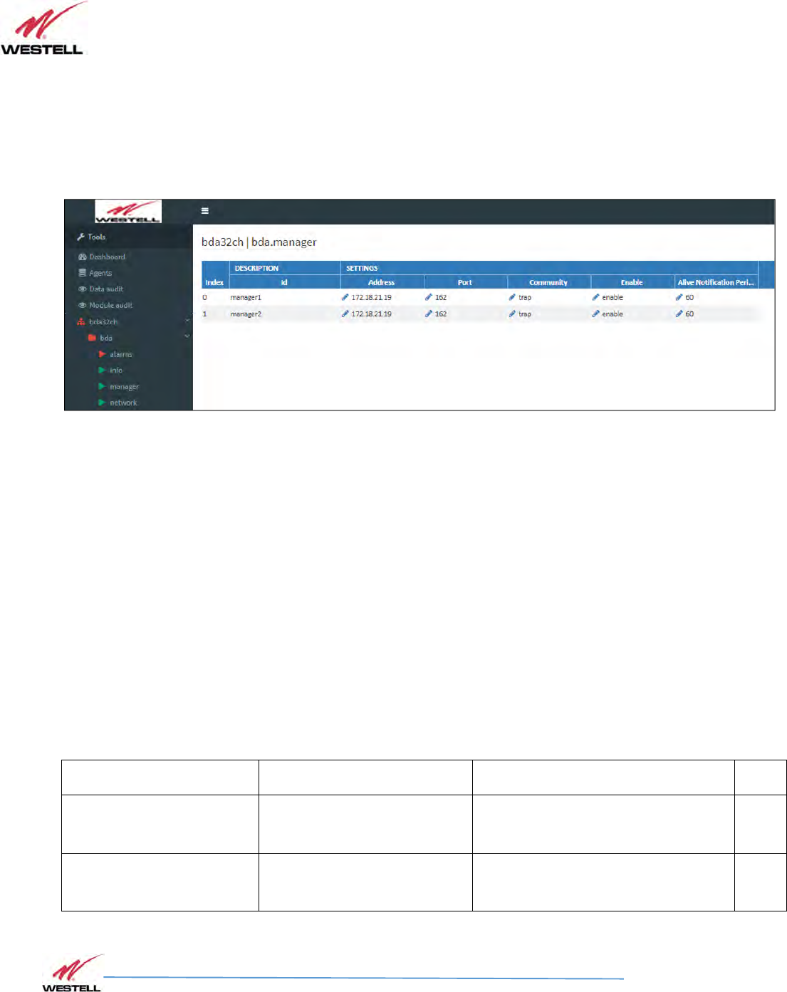
The following picture shows the same table as seen by the Westell NMS:
NMS: SNMP Managers table
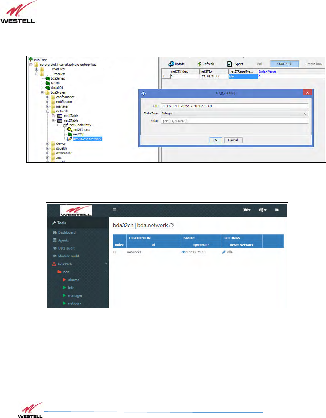
Network
This is a table has just one element with two items. The first one is the device's IP address and
it is read-only to avoid unwanted miss-configuration. This can only be changed by means of the
embedded web server or locally, through USB, by means of the Westell Control Software. The
second item is a “kind” of button intended for resetting the embedded Ethernet hardware
interface.
SNMP Network table
Field Name
OID
Description
Type
Net2TIp[0]
1.3.6.1.4.1.26355.2.50.4.2.1.2.
0 IP address R/O
Net2TResetNetwork[0]
1.3.6.1.4.1.26355.2.50.4.2.1.3.
0
Network reset: reads as
idle
(1), sets to
reset(2) R/W
VHF Product Manual
July 2018, Rev B
WESTELL.COM
©2017 Westell Technologies July 2018; Doc No. VHF Signal Booster UM RA
1.877.844.4274 Page 81 of 95
The following MIB tree representation shows this table and following there is the NMS view:
SNMP Network table
NMS: SNMP Network table
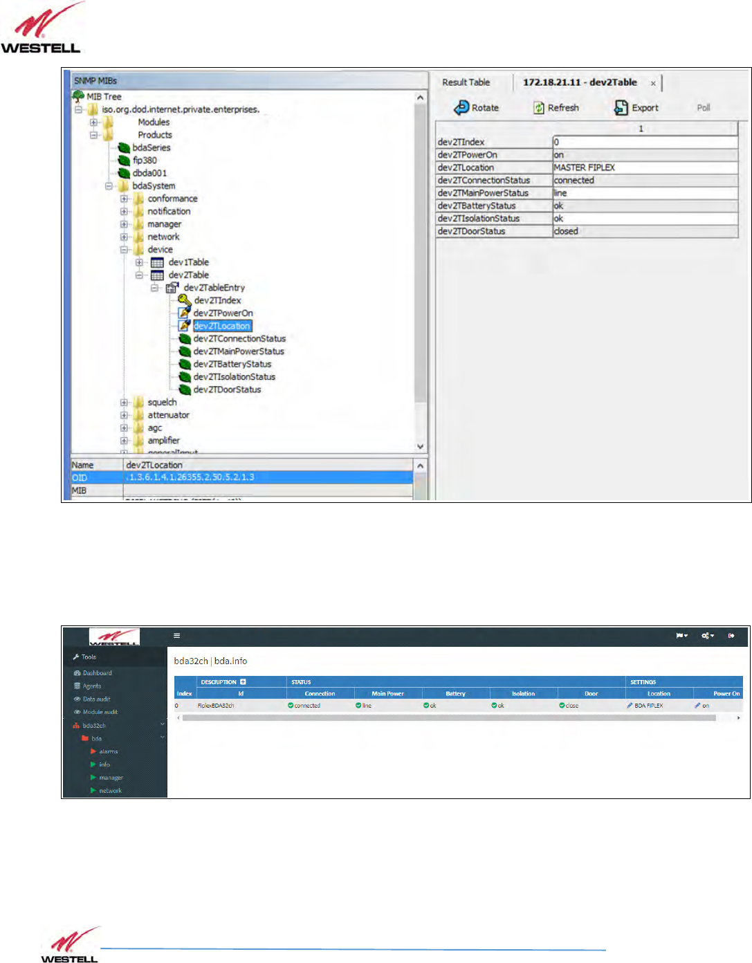
Device
This is also a one element table, providing several informative fields, but only relevant and
implemented one is the “Location” field, which allows to easily identify a device by a name
provided by the user, usually related to the place where it is located.

VHF Product Manual
July 2018, Rev B
WESTELL.COM
©2017 Westell Technologies July 2018; Doc No. VHF Signal Booster UM RA
1.877.844.4274 Page 82 of 95
SNMP Device table
Field Name
OID
Description
Type
Dev2TPowerOn[0]
1.3.6.1.4.1.26355.2.50.5.2.1.2.
0 - R/W
Dev2TLocation[0]
1.3.6.1.4.1.26355.2.50.5.2.1.3.
0 String with up to 30 characters R/W
Dev2TConnectionStatus[0]
1.3.6.1.4.1.26355.2.50.5.2.1.4.
0 - R/O
Dev2TMainPowerStatus[0]
1.3.6.1.4.1.26355.2.50.5.2.1.5.
0 - R/O
Dev2TBatteryStatus[0]
1.3.6.1.4.1.26355.2.50.5.2.1.6.
0 - R/O
Dev2TIsolationStatus[0]
1.3.6.1.4.1.26355.2.50.5.2.1.7.
0 - R/O
Dev2TDoorStatus[0]
1.3.6.1.4.1.26355.2.50.5.2.1.8.
0 - R/O
MIB tree view:
VHF Product Manual
July 2018, Rev B
WESTELL.COM
©2017 Westell Technologies July 2018; Doc No. VHF Signal Booster UM RA
1.877.844.4274 Page 83 of 95
SNMP Device table
The Westell NMS view shows this table under the tab named “info”:
NMS: SNMP Device table
Additional information is shown by clicking on the link named “Description”. This extra piece of
information comes from the fixed table, Dev1Table. The most relevant items in this table are
the following ones:
VHF Product Manual
July 2018, Rev B
WESTELL.COM
©2017 Westell Technologies July 2018; Doc No. VHF Signal Booster UM RA
1.877.844.4274 Page 84 of 95
SNMP Device Group table
Field Name
OID
Descri
ption
Type
Dev1TGroup[0]
1.3.6.1.4.1.26355.2.50.5.1.1.3.
0 das.info (conformance group) R/O
Dev1TurlExtern[0]
1.3.6.1.4.1.26355.2.50.5.1.1.1
9.0 URL of embedded web server R/O
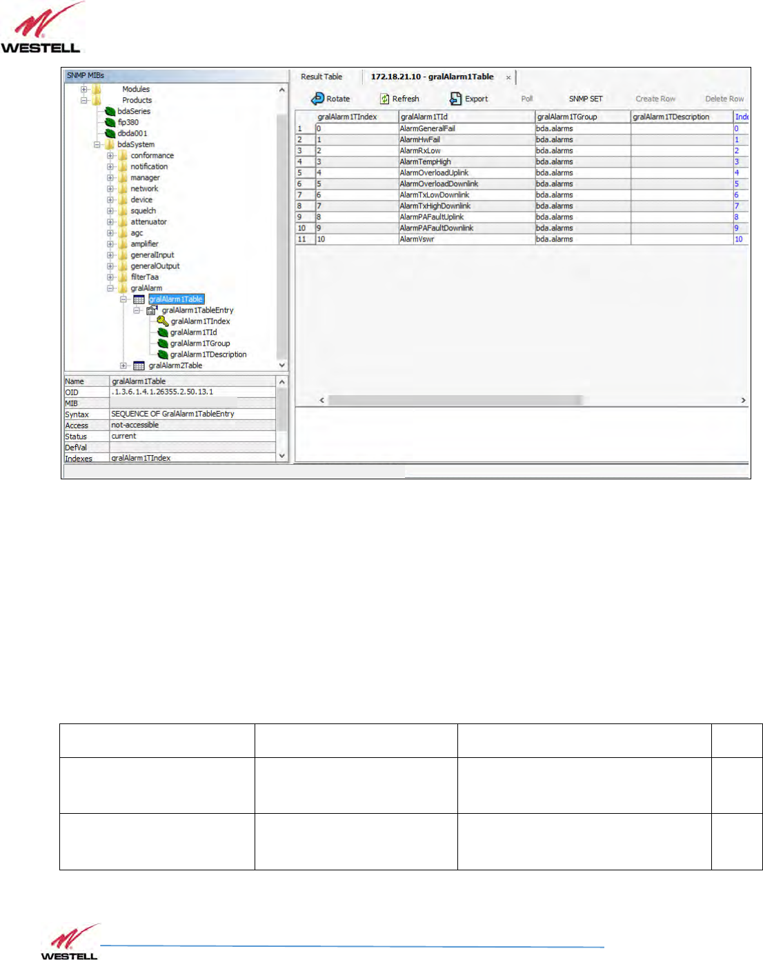
Alarms
Alarms tables provide information regarding the status of key parts in the system. The fixed
table gralAlarm1Table provides self-explanatory identifiers, gralAlarm1TId, for each relevant
subject. The second item in each element of this table is the gralAlarm1TGroup. When the
device being monitored is a Remote unit, this item just takes the value 'das.alarms '. However,
since the Master unit carries information from all the devices in the whole DAS system, it
provides a different value for each device to which the alarm is assigned to, be it the Master
unit, any of the Remote units or any of the Expansion units. Therefore, the actual number of
elements in this table for the Master unit, depends on how many devices compose the DAS
system. The third item of each element, gralAlarm1TDescription, is left blank, since the first
one suffices for that purpose.
SNMP Alarm Group table
Field Name
OID
Description
Type
GralAlarm1TId[0]
1.3.6.1.4.1.26355.2.50.13.1.1.
2.0 Descriptive identifier string R/O
GralAlarm1TGroup[0]
1.3.6.1.4.1.26355.2.50.13.1.1.
3.0 Conformance group for general alarms R/O
GralAlarm1TDescription[0]
1.3.6.1.4.1.26355.2.50.13.1.1.
4.0 - R/O

VHF Product Manual
July 2018, Rev B
WESTELL.COM
©2017 Westell Technologies July 2018; Doc No. VHF Signal Booster UM RA
1.877.844.4274 Page 85 of 95
The alarm identifiers available are the following ones:
• AlarmGeneralFail Board malfunction that cannot be determined.
• AlarmHwFail Digital signal processor failure.
• AlarmRxLow No input signal is detected in the downlink direction in any of the
activated filters. Aside from a faulty part, as the donor antenna or RF cable, this also might be
caused be a problem with the base station or frequency configuration. Notice also that signal
detection is dependent on squelch threshold setting. Because of that, this is considered a warning
instead of an alarm.
• AlarmTempHigh High device temperature (over 85ºC).
• AlarmOverloadUplink Excessive RF input signal in UL.
• AlarmOverloadDownlink Excessive RF input signal in DL.
• AlarmTxLowDownlink Detected RF output power much lower than expected. Since output
power measurement is performed by the dedicated monitoring board, a fault in that board would
make this item be set as Unavailable and AlarmPAFaultDownlink set to true.
• AlarmTxHighDownlink Excessive RF output power detected (3dB higher than rated). This is most
likely due to bad gain settings, since AGC would limit output power otherwise.
• AlarmPAFaultUplink Uplink Power Amplifier failure. This alarm is available for certain amplifier
types only, and for the rest an 'unavailable' status is set in the next table.
• AlarmPAFaultDownlink Downlink Power Amplifier failure. A communication failure with the
dedicated monitoring board itself, throws this alarm, too.
• AlarmVswr RF mismatch of PA output is detected. Since VSWR measurement is
performed by the dedicated monitoring board, a fault in that board would make this item be set
as Unavailable and AlarmPAFaultDownlink set to true.
VHF Product Manual
July 2018, Rev B
WESTELL.COM
©2017 Westell Technologies July 2018; Doc No. VHF Signal Booster UM RA
1.877.844.4274 Page 86 of 95
SNMP Alarms Group table
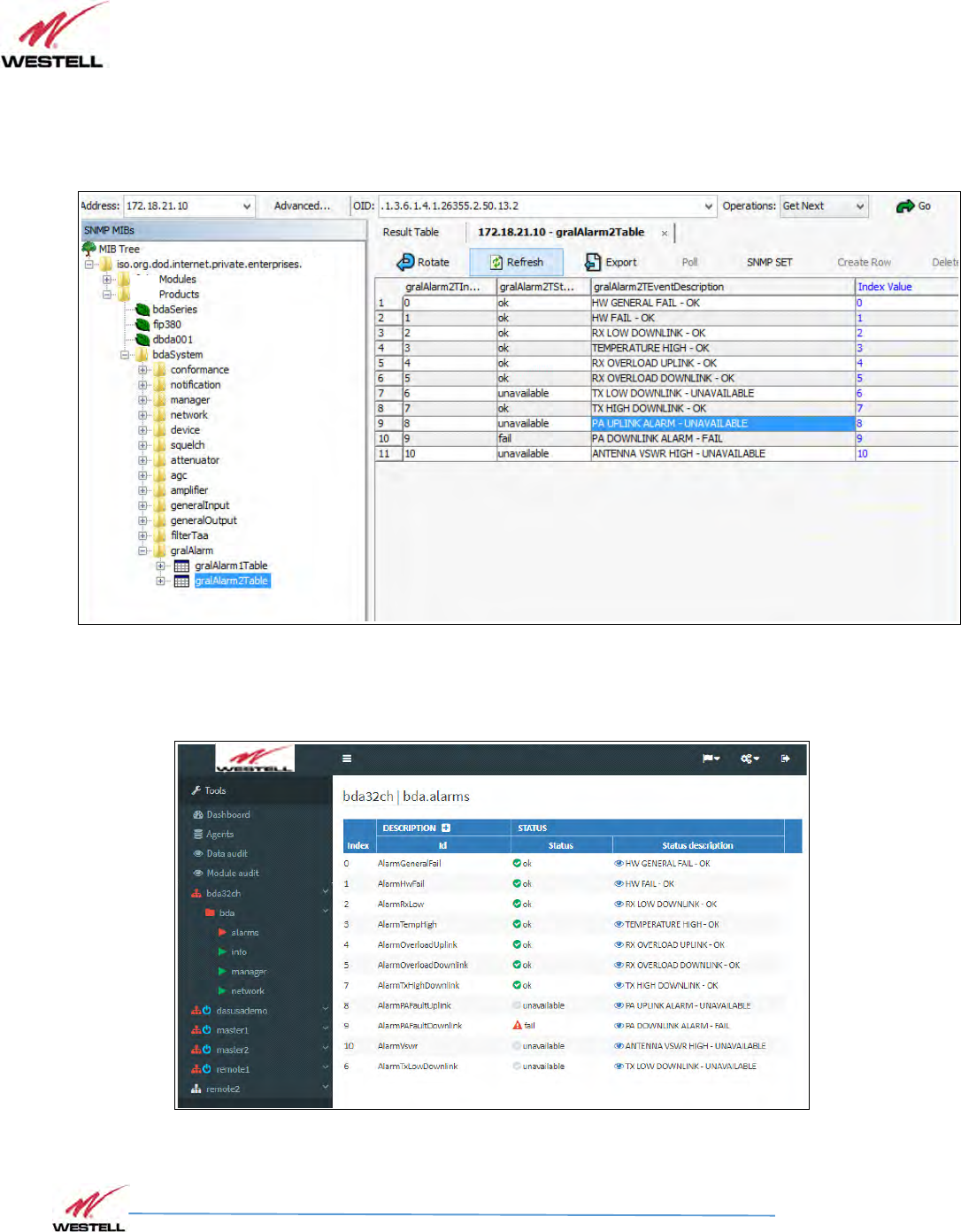
On the other hand, the mutable table gralAlarm2Table provides the actual status of each
alarm. This table has one element for each element in gralAlarm1Table. Each element has two
items. The first one is a status identifier, gralAlarm2TStatus, be it 'ok', 'warning', 'fail' or
'unavailable'. The second item is a short description of the fault, mainly for human readability.
SNMP Alarm table 2
Field Name
OID
Description
Type
GralAlarm2TStatus[0]
1.3.6.1.4.1.26355.2.50.13.2.1.
2.0 Status enumeration R/O
GralAlarm2TEventDescriptio
n[0]
1.3.6.1.4.1.26355.2.50.13.2.1.
3.0 Short descriptive string R/O
VHF Product Manual
July 2018, Rev B
WESTELL.COM
©2017 Westell Technologies July 2018; Doc No. VHF Signal Booster UM RA
1.877.844.4274 Page 87 of 95
The next picture is the MIB tree view of this table, and the Westell NMS provides a combined
view of both tables and groups alarms:
SNMP Alarms table
NMS: SNMP Alarms table

VHF Product Manual
July 2018, Rev B
WESTELL.COM
©2017 Westell Technologies July 2018; Doc No. VHF Signal Booster UM RA
1.877.844.4274 Page 88 of 95
14
1414
14
SNMP Traps
SNMP TrapsSNMP Traps
SNMP Traps
General Explanation
For any event that may set or clear an alarm in the gralAlarm2Table, there is a SNMP trap that
may be sent by the embedded SNMP agent to the manager, if enabled. Therefore, the list of
traps closely reassembles the entries in the alarms table. Furthermore, there is also a keep-
alive trap for letting the SNMP manager that the agent is working, in case that polling is not
being done.
Each trap message has the following fields (except for the keepAlive trap, whose only object is
the agent's IP address
• An identification number associated to the event being signaled.
• A severity indication number.
• A short string description for human readability.
The following list gathers all the available identifiers:
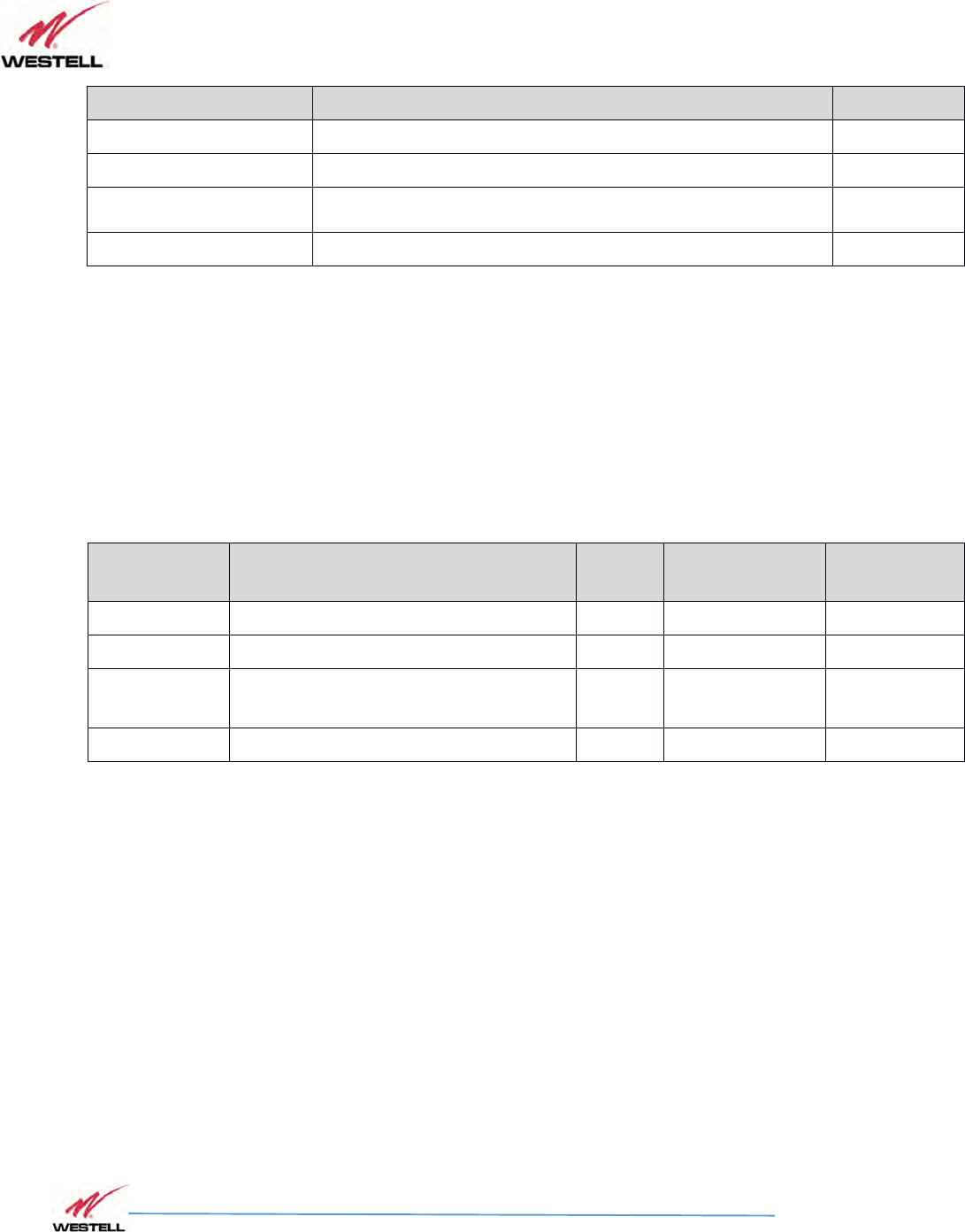
SNMP Trap descriptions and Enterprise Specific IDs
Source event Description ID
Keep-alive
System sends this trap periodically. Period is set with Keep-
Alive Period setting of the trap manager. When this trap is
thrown, the trap counter is not incremented. It is always in
cleared state.
3
General Failure This trap indicates that the board controller is not responding
to the remote supervision system. 5
Hardware Failure This trap indicates malfunction related the Digital Signal
Processor. 6
Rx Input Low DL Downlink input signal is not detected in any active filters. 10
Temperature Internal repeater temperature exceeds +85ºC. 11
Rx Overload UL Uplink RF input level overload 20
Rx Overload DL Downlink RF input level overload 21
Tx Low DL Detected Downlink RF output power is lower than expected. 30
VHF Product Manual
July 2018, Rev B
WESTELL.COM
©2017 Westell Technologies July 2018; Doc No. VHF Signal Booster UM RA
1.877.844.4274 Page 89 of 95
Source event Description ID
Tx High DL Downlink RF output power too high 31
PA Fault UL Alarm for the UL Power Amplifier if available. 40
PA Fault DL Alarm for the DL Power Amplifier. It may be caused by communication
error with PA monitoring module. 41
VSWR Excessive DL output reflected power: antenna mismatch. 50
As it turns out from this list, there is a one-to-one relationship between events triggering traps
and their notification identifiers. But the trap identifier does not tell whether the event was to
trigger the alarm state or to cancel it. That is the purpose of the severity identification number
in the trap message. The following table lists the severity numbers used:
SNMP Trap status binding
Severity Description StatusID Trap status
binding Binding string
CRITICAL System malfunction comes into effect 1 3 fail
WARNING System warning comes into effect. 4 2 warning
CLEARED System malfunction or warning is
canceled. 5 1 ok
UNAVAILABLE System state cannot be determined 6 99 unavailable
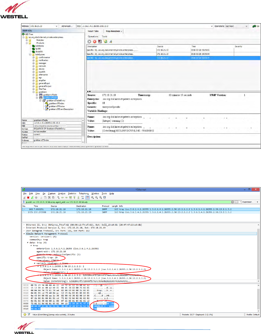
The character string attached to each trap message includes both a short event description
plus a severity description such as “OK” or “FAIL”. As an example, the following picture shows a
snapshot of a trap receiver getting traps from a unit at address 172.18.21.10. The time-stamp
shows time since system boot and SNMP Version is '1'. The severity is set to 'warning'.
VHF Product Manual
July 2018, Rev B
WESTELL.COM
©2017 Westell Technologies July 2018; Doc No. VHF Signal Booster UM RA
1.877.844.4274 Page 90 of 95
SNMP Trap in trap receiver
Example trap capture

VHF Product Manual
July 2018, Rev B
WESTELL.COM
©2017 Westell Technologies July 2018; Doc No. VHF Signal Booster UM RA
1.877.844.4274 Page 91 of 95
SNMP Trap capture
Trap data explained:
Enterprise: .1.3.6.1.4.1.26355 (Westell Inc.)
BDA System MIB: .1.3.6.1.4.1.26355.2.50 (applicable to BDA system)
Enterprise specific trap number: 10 (meaning '
Rx Input Low DL
' according to the table of trap
identifiers).
Trap Bindings
1) gralAlarm2TStatus. Value: 2 (see table below)
2) gralAlarm2TEventDescription: Value: “RX LOW DOWNLINK - WARNING”
The first binding in the trap is the gralAlarm2TStatus of gralAlarm2T table in the MIB:
gralAlarm2TStatus OBJECT-TYPE
SYNTAX INTEGER { ok(1), warning(2), fail(3), unavailable(99) }
MAX-ACCESS read-write
STATUS current
DESCRIPTION
"-"
::= { gralAlarm2TableEntry 2 }
and its equivalence to the trap severity is explained in the table shown in previous section.
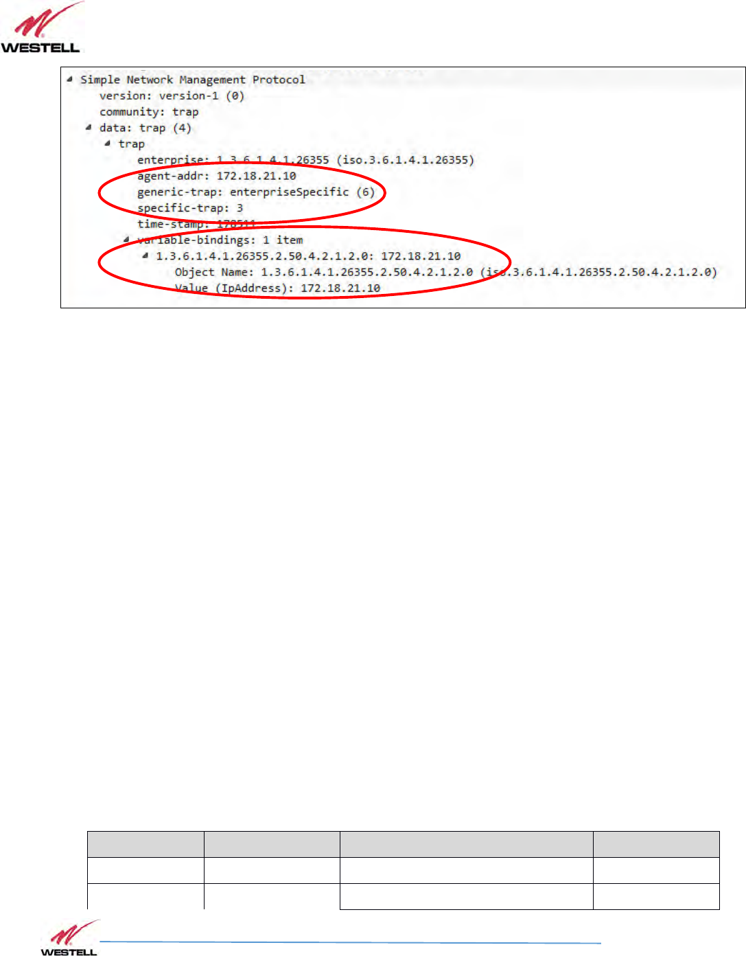
The second binding is the string used to be human-readable. The only different type of trap is
the keep-alive one, which as an example is shown in next picture:
VHF Product Manual
July 2018, Rev B
WESTELL.COM
©2017 Westell Technologies July 2018; Doc No. VHF Signal Booster UM RA
1.877.844.4274 Page 92 of 95
SNMP Keep-alive trap capture
and its only binding is the net2TIp part of the net2Table in the MIB
net2TIp OBJECT-TYPE
SYNTAX IpAddress
MAX-ACCESS read-only
STATUS current
DESCRIPTION
"-"
::= { net2TableEntry 2}
List of traps
The following table lists all bindings in each trap for convenience:
SNMP Trap list
Source event Specific Trap ID Bindings Value
Keep-alive 3 1.3.6.1.4.1.26355.2.50.4.2.1.2.0 Ip Address
General Failure 5 1.3.6.1.4.1.26355.2.50.13.2.1.2.0 {1, 2, 3, 99}

VHF Product Manual
July 2018, Rev B
WESTELL.COM
©2017 Westell Technologies July 2018; Doc No. VHF Signal Booster UM RA
1.877.844.4274 Page 93 of 95
Source event Specific Trap ID Bindings Value
1.3.6.1.4.1.26355.2.50.13.2.1.3.0 String
Hardware Failure 6 1.3.6.1.4.1.26355.2.50.13.2.1.2.1 {1, 2, 3, 99}
1.3.6.1.4.1.26355.2.50.13.2.1.3.1 String
Rx Input Low DL 10 1.3.6.1.4.1.26355.2.50.13.2.1.2.2 {1, 2, 3, 99}
1.3.6.1.4.1.26355.2.50.13.2.1.3.2 String
Temperature 11 1.3.6.1.4.1.26355.2.50.13.2.1.2.3 {1, 2, 3, 99}
1.3.6.1.4.1.26355.2.50.13.2.1.3.3 String
Rx Overload UL 20 1.3.6.1.4.1.26355.2.50.13.2.1.2.4 {1, 2, 3, 99}
1.3.6.1.4.1.26355.2.50.13.2.1.3.4 String
Rx Overload DL 21 1.3.6.1.4.1.26355.2.50.13.2.1.2.5 {1, 2, 3, 99}
1.3.6.1.4.1.26355.2.50.13.2.1.3.5 String
Tx Low DL 30 1.3.6.1.4.1.26355.2.50.13.2.1.2.6 {1, 2, 3, 99}
1.3.6.1.4.1.26355.2.50.13.2.1.3.6 String
Tx High DL 31 1.3.6.1.4.1.26355.2.50.13.2.1.2.7 {1, 2, 3, 99}
1.3.6.1.4.1.26355.2.50.13.2.1.3.7 String
PA Fault UL 40 1.3.6.1.4.1.26355.2.50.13.2.1.2.8 {1, 2, 3, 99}
1.3.6.1.4.1.26355.2.50.13.2.1.3.8 String
PA Fault DL 41 1.3.6.1.4.1.26355.2.50.13.2.1.2.9 {1, 2, 3, 99}
1.3.6.1.4.1.26355.2.50.13.2.1.3.9 String
VSWR 50 1.3.6.1.4.1.26355.2.50.13.2.1.2.10 {1, 2, 3, 99}
1.3.6.1.4.1.26355.2.50.13.2.1.3.10 String

VHF Product Manual
July 2018, Rev B
WESTELL.COM
©2017 Westell Technologies July 2018; Doc No. VHF Signal Booster UM RA
1.877.844.4274 Page 94 of 95
Appendix A Important Product Information
A.1 Registration Number
FCC – NVRPSA41080-VHF
A.2 UL
This product is UL Listed.

VHF Product Manual
July 2018, Rev B
WESTELL.COM
©2017 Westell Technologies July 2018; Doc No. VHF Signal Booster UM RA
1.877.844.4274 Page 95 of 95
Appendix B Acronyms and Abbreviations
Table B-1 contains the acronyms and abbreviations used in this manual, along with a definition for
each one.
Table B-1: Acronyms and Abbreviations
AGC Automatic Gain Control
AMPS Advanced Mobile Phone Service
ARFCN Absolute Radio Frequency Channel Number
BCCH Broadcast Control Channel (GSM broadcast channel time slot)
BS Base Station, BS antenna = towards the base station
CDMA Code Division Multiple Access
DC Direct Current
DCS Digital Communication System (same as PCN)
DL
Downlink signal direction (from base station via Signal Booster / Master / Remote to mobile
station)
DPLX Duplex filter
EEPROM Electrical Erasable Programmable Read Only Memory
EGSM Extended Global System for Mobile communication
ETACS Extended Total Access Communication System
ETSI European Telecommunications Standard Institute
WCS Westell Control Software
GSM Global System for Mobile communication
HW Hardware
LED Light Emitting Diode
LNA Low Noise Amplifier, uplink and downlink
MS Mobile Station, MS antenna = towards the mobile station
OL Overload
OMS Operation and Maintenance System
PA Power Amplifier
PCN Personal Communication Network (same as DCS)
PCS Personal Communication System
pWOMS Portable Westell Operation and Maintenance Software
PS Power Supply
RF Radio Frequency
RSSI Received Signal Strength Indication
SW Software
UL Uplink signal direction (from mobile station via Signal Booster / Master / Remote to base station)
WEEE Waste of Electric and Electronic Equipment