Western Auto AYP9187B89 User Manual WIZARD LAWN TRACTOR Manuals And Guides 98080197
WESTERN AUTO Lawn, Tractor Manual 98080197 WESTERN AUTO Lawn, Tractor Owner's Manual, WESTERN AUTO Lawn, Tractor installation guides
User Manual: Western Auto AYP9187B89 AYP9187B89 WESTERN AUTO WIZARD LAWN TRACTOR - Manuals and Guides View the owners manual for your WESTERN AUTO WIZARD LAWN TRACTOR #AYP9187B89. Home:Lawn & Garden Parts:Western Auto Parts:Western Auto WIZARD LAWN TRACTOR Manual
Open the PDF directly: View PDF ![]() .
.
Page Count: 56

Western Auto
Operation and Service Instructions
Wizard Lawn Tractor
Stock Number
93-9187-1 Model Number
AYPS187B89: p _Dr.
Factory Number
9187B89
Thank you for purchasing an American-built product.
A SAFE RULES A
Safe Operation Practices for Ride-On Mowers
IMPORTANT: THIS CUTTING MACHINE IS CAPABLE OF AMPUTATING HANDS AND FEET AND THROWING OBJECTS.
FAILURE TO OBSERVE THE FOLLOWING SAFETY INSTRUCTIONS COULD RESULT IN SERIOUS INJURY OR DEATH.
I. GENERAL:OPERATION
• Read, understand,andfollowall instructionsinthe manual
andonthe machine beforestarling.
• Only allow responsibleadults,who are familiar with the
instructions,to operatethe machine.
•Clear the area of objects such as rocks,toys,wire, etc.,
which couldbe pickedup andthrownbythe blade.
•Besurethearea isclearofotherpeoplebeforamowing.Stop
machineif anyone entersthe area.
•Nevercarrypassengers.
• Donotmowinreverseunlessabsolutelynecessary.Always
lookdownandbehindbeforeandwhilebacking.
•Be aware ofthe mowerdischargedirectionanddonotpoint
it at anyone. Do not operatethe mowerwithouteitherthe
__ entiregrasscatcheror the guardin place.
-• _low downbefore turning.
•Neverleave a runningmachineunattended.Alwaysturnoff
blades,set parkingbrake, stopengine, and removekeys
beforedismounting.
•Turnoff bladeswhennotmowing.
•Stop enginebefore removinggrasscatcheror unclogging
chute.
•Mow onlyindaylightor goodartificiallight.
•Do not operatethe machinewhile underthe influenceof
alcoholor drugs.
•Watchfortrafficwhenoperating nearorcrossingroadways.
•Use extracare whenloadingor unloadingthe machineinto
a trailerortruck.
II. SLOPE OPERATION
Slopes are a major factor related to loss-of-control and
tipover accidents, which can'result in severe injury or
death. All slopes require extra caution. If you cannot back
up the slope or if you feel uneasy on it, do not mow it.
DO:
•Mowup and downslopes,not-across.
•Removeobstaclessuchas rocks,tree limbs,etc.
•Watch for holes, ruts, or bumps. Uneven terraincould
overturnthe machine. Tallgrass can hideobstacles.
•Useslowspeed. Choosea lowgearsothatyouwillnothave
to stoporshittwhileon the slope.
• Follow the manufacturer's recommendationsfor wheel
weightsorcounterweightsto improvestability.
-_ Use extra care with grasscatchersor other attachments.
_- Thes_Canchangethe st-'=,bilityof the machine.
•Keepall movementonthe slopesslowandgradual.Donot
makesuddenchangesin speedordirection.
=• Avoidstartingor stoppingon a slope. If tireslosetraction,
disengagethe bladesandproceedslowlystraightdownthe
slope.
DO NOT:
Donotturnonslopesunlessnecessary,andthen,tumslowly
and graduallydoV_12_ill,if possible.
•Do notmow neardrop-offs,ditches,orembankments.The
mowercouldsuddenlytum over ifa wheelis overthe edge
of a cliffor ditch,orif an edgecaves in.
•Do not mow on wet grass. Reducedtractioncouldcause
sliding.
•Donottrytostabilizethemachinebypuffingyourfootonthe
ground.
• Do notusegrasscatcheronsteep slopes.
III. CHILDREN
Tragic accidentscan occur if the operator is notalert to the
presence of children. Children are often attracted to the
machine and the mowing activity. Never assume that
children will remain where you last saw them.
•Keepchildrenoutofthe mowingarea andunderthewatchful
careof another responses adult.
•Be alertandturnmachineoffif childrenenterthe area.
•Beforeandwhenbacking,lookbehindand downfor small
children.
•Never carrychildren. They may fall off and be seriously
injuredorintederewithsafe machineoperation.
•Neverallowchildrento operate the machine.
•Use extra care when approachingblind comers, shrubs,
trees,orotherobjectsthatmay obscurevision.
IV. SERVICE
•Useextracareinhandlinggasolineandotherfuels.Theyare
flammableandvaporsare explosive.
-Use onlyan approvedcontainer.
Never remove gas cap or add fuel with the engine
running.Alloweng=neto coolbeforerefueling. Do not
smoke.
Neverrefuelthe machineindoors.
Neverstorethe machineor fuel containerinsidewhere
thereis anopenflame,suchas a waterheater.
•Neverruna machineinsidea closedarea.
•Keepnutsandbolts,especiallyblade attachmentbolts,tight
and keepequipmentingoodcondition.
•Never tamper with safety devices. Check their prope
operationregularly.
•Keepmachinefree ofgrass,leaves,orotherdebrisbuild-up.
Clean oil or fuel spillage. Allow machine to cool before
storing.
•Stop and inspectthe equipmentif you strikean object.
Repair,ifnecessary,beforerestarting.
•Nevermakeadjustmentsor repairswiththeenginerunning.
•Grasscatchercomponentsaresubjecttowear,damage,and
deterioration,which couldexpose movingparis or allow
objectsto be thrown. Frequentlycheck componentsand
replacewithmanufacturer'srecommendedparis,whennec-
essary.
•Mowerbladesare sharpand cancut. Wrap theblade(s)or
wear gloves,anduse extracautionwhenservicingthem.
•Checkbrakeoperationfrequently. Adjustand serviceas
required.
I& Lookforthissymboltopointoutimportant
safety precautions. It means
CAUTIONIII BECOME ALERTII! YOUR
SAFETY IS INVOLVED.
IA CAUTION: Always disconnect spark plug
wire and place wire where it,candot contact
spark plug in order to pre,Tent accidental
starting when setting up, transporting,
adjusting or making repairs.
A WARNING A
The engine exhaust from this product contains
chemicals known to the State of California to
cause cancer, birth defects, or other reproduc-
tive harm.
2

CONGRATULATIONS :.on ypur purch_6i_a new Tm(_' !
tor. It has been designed, erlgineered and manufactured _
to give you the best poss_le dependability and perfor-
mance.
Should you e'_pedence any problem you cannot easily
remedy, please contact your nearest authorized service
center. We have competent, well-trained techntdans and
the proper tools to service Or repair this tractor.
Please read and retain this manual. The instructions will
enable you to assemble and maintain your tractor prop-
erly. Always observe the •SAFETY RULES'.
PRODUCT SPECIFICATIONS
HORSEPOWER: 18.0
GASOLINE CAPACITY 3.5 GALLONS
AND TYPE: UNLEADED REGULAR
-
OIL TYPE (API-SF/SG/SH): See "ENGINE" in Customer
Responsibilities Section
OIL CAPACITY: W/FILTER: 3.5 PINTS
W/O FILTER: 3.0 PINTS
SPARK PLUG: CHAMPION RJ19LM
(GAP: .030")
VALVE CLEARANCE: INTAKE: .004" - .006"
EXHAUST: .007" - .009"
GROUND SPEED (MPH): Forward: 0-5.7
Reverse 0-2.5
TIRE PRESSURE: FRONT: 14 PSI
REAR: 10 PSI
CHARGING SYSTEM: 3 AMPS Battery
5 AMPS Battery
BATTERY: AMP/HR: 30
MIN. CCA: 240
CASE SIZE: UIR
BLADE BOLT TORQUE: 27-35 FT. LBS.
MODEL • _ _ ,
NUMBER " AYP9187B89
SERIAL
NUMBER
DATE OF PURCHASE
THE MODEL AND SERIAL NUMBERS WILL BE FOUND ON A
PLATEUNDER THE SEAT.
YOU SHOULD RECORD BOTHSERIAL NUMBER AND DATE OF
PURCHASEAND KEE° INA SAFE PLACE FOR FUTURE REFER-
ENCE.
CUSTOMER RESPONSIBILITIES
•Read and observe the safety rules.
•Follow a regular schedule in maintaining, caring for and
using your tractor.
•Follow the instructions under the "Customer Responsibili-
ties" and "Storage • sections of this owner's manual.
WARNING: This tractor is equipped with an internal combustion
engine and should notbe used onor near any unimproved forest-
covered, brush-covered orgrass-covered land unlessthe engine's
exhaust system is equipped with a spark arrester meeting appli-
cable local or state laws (if any). If aspark attester is used, it
should be maintained in effective working order by the operator.
In the state of California the above is required by law (Section
4442 of the California Public Resources Code). Otherstates may
have similar laws. Federal laws apply on federal lands.
3

TABLE.OF CONTENTS:"
SAFETY RULES ......................................... -.................. 2
PRODUCT SPECIFICATIONS .................................... 3
CUSTOMER R_SPONSlBILmES ..................... 3, 15-19
WARRANTY. ........................ •........................ ,............ 4
ASSEMBLY ............... •........... •.................................... 5-8
OPERATION ............................................................. 9-14
MAINTENANCE SCHEDULE ...................................... 15
SERVICE AND ADJUSTMENTS ............................ 20-25
STORAGE ................................................................. 2€
TROUBLESHOOTING ............................................ 27-28
REPAIR PARTS - TRACTOR ................................. 30-47
REPAIR PARTS - ENGINE .................................... 48-54
PARTS ORDERING/SERVICE ................ BACK COVER
WESTERN AUTO TRACTOR LIMITED WARRANTY
AYP9187B89
- Westem AutoSupplyCompanyWarrantstothe originalretailpurchaserthatthisproductisfree fromdefectsinmaterialor
workmanshipandagreesto repairthis productfree of chargewithinthesetimeperiodsfromthe date of purchase:
• 2 years,if the productis usedfor personal,family, orhouseholduse;
• 90 days,if the productis usedforany otherpurposesuchas commercialor rentaluse.
Excludedfrom thiswarrantyare normalwear, maintenance,or mechanicaladjustmentswhichare notdue to defectsin
materialorworkmanship.Consultyourowner'smanualforhelpto maintainyourproductormakemechanicaladjustments.Products
whichhavebeenaltered,misused,abused,orrepairedbyotherthanaWesternAuto-authorizedocmanufacturer-authorizedservice
facility are alsoexcluded.
A rider ortractorbatterywhichprovesdefectivewithin90 dayswill be replacedwithoutcharge. After90 daysbutwithin1
year from the date of purchase,WesternAutowill replacethe batteryfor a chargeof 1/12 of the currentretailpriceof the battery
for each full monthbetweenthe date ofpurchaseandthe dateof return.
Enginesor transaxlesare warrantedby the engineortransaxlemanufacturerwhichgives its own 2 year warrantyand
providesservicethroughitsauthorizedservicefacilities.Seetheengineortransaxlewarrantyfordetails.Repairmaybe arranged
throughparticipatingWestern Autostores.
Forrepairserviceretumthisproductwithproofofpurchasedate to a participatingWestemAutostore.Thiswarrantygives
youspecificlegalrightsandyoumayhaveotherrightsthatvaryfrom stateto state. Ifdifficultyis encounteredinhavingthiswarranty
honored,contact: WesternAutoSupplyCompany
ConsumerAffairsSectionof the GeneralServiceDepartment
2107 GrandAvenue,KansasCity,Missouri64108
Telephone: 816 346-4411
4
:_i_. :_ _-_. :- : 4¸ , ,..L. _: :... _ .... _ • _ .•
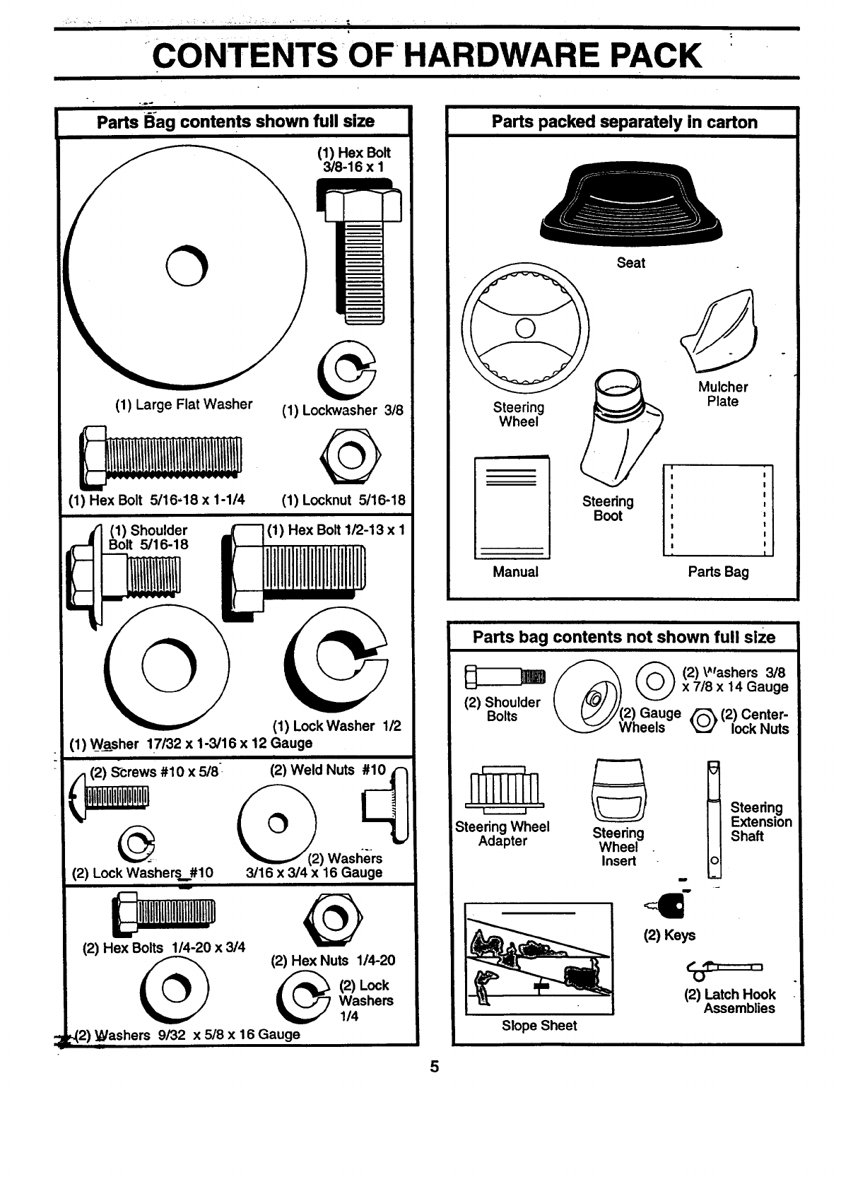
CONTENTS OF HARDWARE PACK
o.
Parts B_agcontents shown full size
(1) Hex Bolt
3/8-16 x I
©
(1) Large Flat Washer
(1) Hex Bolt 5/16-18 x 1-1/4
(1) Lockwasher 3/8
Q
(1) Locknut 5/16-18
(1) Shoulder
Bolt 5/16-18 (1) Hex Bolt 1/2-13 x I
(1) Lock Washer 1_/2
(1) Washer 17/32 x 1-3/16 x 12 Gauge
I
/_(2) Shrews #10 x 5/8 _(2) Weld Nuts #10 _'_
lllltitltltltlililtltlti ) Wast_ers
(2) Lock Washers #10 3/16 x 3/4 x 16 Gauge
(2) Hex Bolts 1/4-20 x 314
(2) Hex Nuts 1/4-20
(2) Lock
Washers
1/4
._2) L_/ashers 9/32 x 5/8 x 16 Gauge
5
Parts packed separately in carton
Seat
Mulcher
Steering Plate
Wheel
|
Steering
Boot
i
Manual Pads Bag
Parts bag contents not shown full size
(_ (2)Washers 3/8x 7/8 x 14 Gauge
(2) Shoulder
Bolts 12)Gauge _(2) Center-
Wheels _lock Nuts
II I m
Steering Wheel Steering
Adapter Wheel
Insert
Slope Sheet
(2) Keys
Steering
Extension
Shaft
€, ,,_------. _
U
(2) Latch Hook
Assemblies

ASSEMBLY
Your new tractor has been assembled at the factorywith exception of those parts left unassembled for shipping purposes.
To ensure safe arKtprOperoperation of your tractor all parts and hardware you assemble must be tightened securely. Use
the correct tools as necessary to insure proper tightness.
TOOLS REQUIRED FOR ASSEMBLY
A socket wrench set will make assembly easier. Standard
wrench sizes are listed.
(1) 3/4" Socket w/drive rachet Utility knife
(2) 7116" wrenches Tire pressure gauge
(2) 112"wrenches Phillips Screwdriver
(1) 9/16" wrench
When right or left hand is mentioned in this manual, it
means when you are in the operating position (seated
behindthe steering wheel).
TO REMOVE TRACTOR FROM CARTON
UNPACK CARTON
•Remove all accessible loose parts and parts cartons
from carton (See page 5).
•Cut, from top to bottom, along lines on all four comers
of carton, and lay panels flat.
•Check for any additional loose parts or cartons and
remove.
BEFORE ROLLING TRACTOR OFF SKID
A'I-rACH STEERING WHEEL (See Fig. 1)
ASSEMBLE EXTENSION SHAFT AND BOOT
•Slide extension shaft onto lower steering shaft. Align
mounting holes in extension and lower shafts and
install 5/16 hex bolt and Iocknut. Tighten securely.
IMPORTANT: TIGHTEN BOLT AND NUT SECURELY TO
18-22 FT. LBS TORQUE.
•Place tabs of steering boot over tab slots in dash and
push down to secure.
INSTALL STEERING WHEEL
• Position front wheels of the tractor so they are pointing
straight forward.
Slide steering wheel adapter onto steering shaft exten-
sion.--
Position steering wheel So cross bars are horizontal
(left to right) and slide inside boot and onto adapter.
•Assemble large flat washer, 3/8 lock washer, 3/8 hex
"bolt and tighten securely.
•Snap steering wheel insert into center of steering
wheel. _ _;i
•Remove protectivematerials from tractor hood and
grill. .-
IMPORTANT: CHECK FOR AND REMOVE ANY STAPLES
IN SKID THAT MAY PUNCTURE TIRES WHERE TRACTOR
IS TO ROLL OFF SKID.
STEERING
WHEEL
'_ --INSERT
3/8HEX BOLT
3/8LOCK WASHER
(_ LARGE FLAT
WASHER
ADAPTER
STEERING
BOOT
_ _,_. EXTENSION SHAFT
. ____ 5/16 HEX BOLT
5/16 LOCKNUT /" - I" _ ._._..
I/. 17 'I
LOWER ,,,_l= .. _ "', ,' ;
STEERING _ _ ,I
FIG. 1
TO ROLL TRACTOR OFF SKID (See Opera-
tion section for location and function of con-
trols)
•Press liftlever plungerand raise attachment liftleverto
its highest position.
•Release parking brake by depressing clutch/brake
pedal.
•Place freewheel control in freewheeling position to
disengage transmission (See "TO TRANSPORT" in
the Operation section of this manualp. -
•Roll tractor forward off skid.
•Remove banding holding discharge guard up against
tractor.
6
ASSEMBLY
HOW TO SET UP YOUR TRACTOR
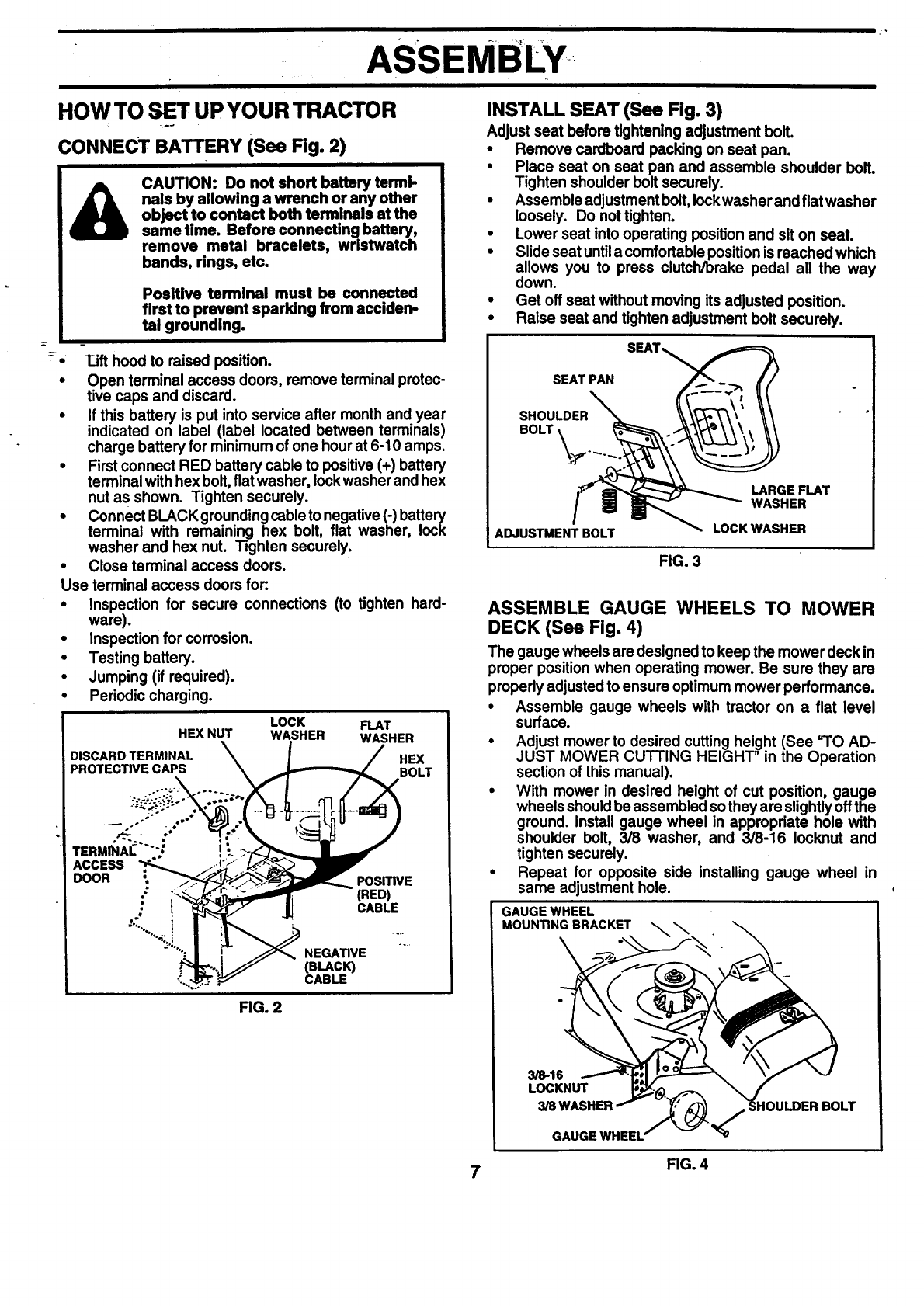
CONNECT BATTERY (See Fig. 2)
CAUTION: Do not short battery terml-
nals by allowing a wrench or any other
object to contact both terminals at the
same time. Before connecting battery,
remove metal bracelets, wristwatch
bands, rings, etc.
I-
Positive terminal must be connected
first to prevent sparking from acciden-
tal grounding.
T_ifthood to raised position.
Open terminal access doors, remove terminal protec-
tive caps and discard.
• If this battery is put into service after month and year
indicated on label (label located between terminals)
charge battery for minimum of one hourat 6-10 amps.
•First connect RED battery cable to positive (+) battery
terminal withhex bolt,flat washer, lockwasher and hex
nut as shown. Tighten securely.
•Connect BLACKgrounding cableto negative (-) battery
terminal with remaining hex bolt, flat washer, lock
washer and hex nut. Tighten securely.
•Close terminal access doors.
Use terminal access doors for:.
•Inspection for secure connections (to tighten hard-
ware).
•Inspection for corrosion.
• Testing battery.
•Jumping (if required).
•Periodic charging.
HEX NUT
DISCARD TERMINAL
PROTECTIVE CAPS
LOCK FLAT
WASHER WASHER
HEX
BOLT
POSITIVE
(RED)
CABLE
NEGATIVE
(BLACK)
CABLE
FIG. 2
INSTALL SEAT (See Fig. 3)
Adjust seat before tightening adjustment boll
•Remove cardboard packing on seat pan.
•Place seat on seat pan and assemble shoulder bolt.
Tighten shoulder bolt securely.
•Assemble adjustment bolt,Iockwasher and flat washer
loosely. Do not tighten.
•Lower seat into operating positionand sit on seat.
•Slide seat untila comfortable positionis reached which
allows you to press clutch/brake pedal all the way
down.
•Get off seat without moving its adjusted position.
• Raise seat and tighten adjustment bolt securely.
SEAT PAN
SHOULDER
BOLT _._.. _..
ADJUSTMENT BOLT
FIG. 3
LARGE FLAT
WASHER
LOCK WASHER
ASSEMBLE GAUGE WHEELS TO MOWER
DECK (See Fig. 4)
The gauge wheels are designed to keep the mower deck in
proper positionwhen operating mower. Be sure they are
properly adjustedto ensure optimum mower performance.
•Assemble gauge wheels with tractor on a flat level
surface.
•Adjust mower to desired cutting height (See =TO AD-
JUST MOWER CUTTING HEIGHT" in the Operation
section of this manual).
•With mower in desired height of cut position, gauge
wheels shouldbe assembled so they are slightlyoffthe
ground. Install gauge wheel in appropriate hole with
shoulder bolt, 3/8 washer, and 3/8-16 Iocknut and
tighten securely.
•Repeat for opposite side installing gauge wheel in
same adjustment hole.
GAUGE WHEEL
MOUNTING BRACKET \
3/8-16
LOCKNUT
GAUGE WHEEL
7FIG. 4
iii
.
ASSEMBLY
Ii
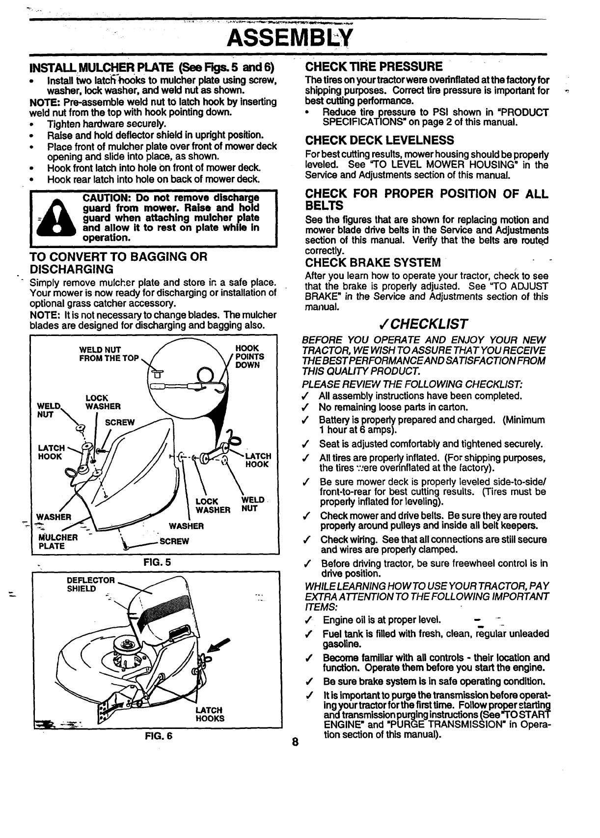
INSTALL MULCHER PLATE (See FKjs.5 and 6)
• Install two latchhooks to mulcher plate using screw,
washer, lock washer, and weld nut as shown.
NOTE: Pre-assemble weld nut to latch hook by inserting
weld nut from the top with hook pointing down.
•Tighten hardware securely.
Raise and hold deflector shield in upright position.
• Place front of mulcher plate over front of mower deck
•opening and slide into place, as shown.
•Hook front latch into hole On front of mower deck.
Hook rear latch into hole on back of mower deck.
|a= CAUTION: Do not remove discharge
I_guard from mower. Raise and hold
I--J_J_ guard when attaching mulcher plate
I_and allow it to rest on plate while in
!_operation.
TO CONVERT TO BAGGING OR
DISCHARGING
Simply remove mulcher plate and store in a safe place.
Your mower is now ready for discharging or installationof
optional grass catcher accessory.
NOTE: It is not necessary to change blades. The mulcher
blades are designed for discharging and bagging also.
HOOK
POINTS
DOWN
WELD NUT
LOCK
HOOK
LOCK WELD.
WASHER NUT
HOOK
WASHER
WASHER
MULCHERpLATE "_......-'SCREW
FIG. 5
p°.
LATCH
HOOKS
DEFLECTOR
SHIELD
CHECK TIRE PRESSURE
The tires onyour tractorwere ovednflated atthe factory for
shipping purposes. Correct tire pressure is important for
best cuffing performance.
• Reduce tire pressure to PSI shown in =PRODUCT
SPECIFICATIONS on page 2 of this manual.
CHECK DECK LEVELNESS
For best cuttingresults, mower housingshould be properly
leveled. See =TO LEVEL MOWER HOUSING" in the
Service and Adjustments section of this manual.
CHECK FOR PROPER POSITION OF ALL
BELTS
See the figures that are shown for replacing motion and
mower blade drive belts in the Service and Adjustments
section of this manual. Verify that the belts are muted
correctly.
CHECK BRAKE SYSTEM
After you learn how to operate your tractor, check to see
that the brake is properly adjusted. See =TO ADJUST
BRAKE" in the Service and Adjustments section of this
manual.
,/CHECKLIST
BEFORE YOU OPERATE AND ENJOY YOUR NEW
TRACTOR, WE WISH TO ASSURE THAT YOU RECEIVE
THE BEST PERFORMANCEAND SATISFACTION FROM
THIS QUALITY PRODUCT.
PLEASE REVIEW THE FOLLOWING CHECKLIST:
,/ All assembly instructionshave been completed.
,/ No remaining loose parts in carton.
,/ Battery is properlyprepared and charged. (Minimum
1 hour at 6 amps).
,/ Seat is adjusted comfortably and tightened securely.
,/ All tires are properlyinflated. (For shipping purposes,
the tires "::ereovednflated at the factory).
/Be sure mower deck is properly leveled side-to-side/
front-to-rear for best cutting results. (Tires must be
properly inflated for leveling).
,/ Check mower and drive belts. Be sure they are routed
properly around pulleys and inside all belt keepers.
/Check wiring. See that allconnections are still secure
and wires are properly clamped.
/Before drivingtractor, be sure freewheel control is in
drive position.
WHILE LEARNING HOW TO USE YOUR TRACTOR, PAY
EXTRA ATTENTION TO THE FOLLOWING IMPORTANT
ITEMS:
/Engine oil is at proper level. - -
,f Fuel tank is filled with fresh, clean, r_gular unleaded
gasoline.
,/ Become familiar with all controls -their location and
function. Operate them before you start the engine.
/Be sure brake system is in safe operating condition.
•/ It is importantto purge the transmission before operat-
ing your tractorfor the firsttime. Follow proper starting
and transmissionpurginginstructions(See =TOSTART
ENGINE" and =PURGE TRANSMISSION" in Opera-
tion section of this manual).
FIG. 6 8

•_OPERATION
These symbols may appear on your tractor or in IRerature supplied with the product. Learn and undemtand their meaning.
BATTERY CAUTION OR REVERSE FORWARD FAST SLOW
WARNING
°
ENGINE ON ENGINE OFF OIL PRESSURE CLUTCH LIGHTS ON OVER TEMP
LIGHT "
CHOKE MOWER HEIGHT DIFFERENTIAL PARKING BRAKE UNLOCKED
LOCK LOCKED
IR N H L
Ill REVERSE NEUTRAL HIGH LOW PARKING BRAKE
MOWER LIFT
ATTACHMENT ATTACHMENT
CLUTCH ENGAGED CLUTCH DISENGAGED KEEP AREA CLEAR SLOPE HAZARDS
(SEE SAFETY RULES SECTION)
DANGER, KEEP HANDS AND FEET AWAY IGNITION FREE WHEEL
(AutomaticModels only)
9
ii OPERATION
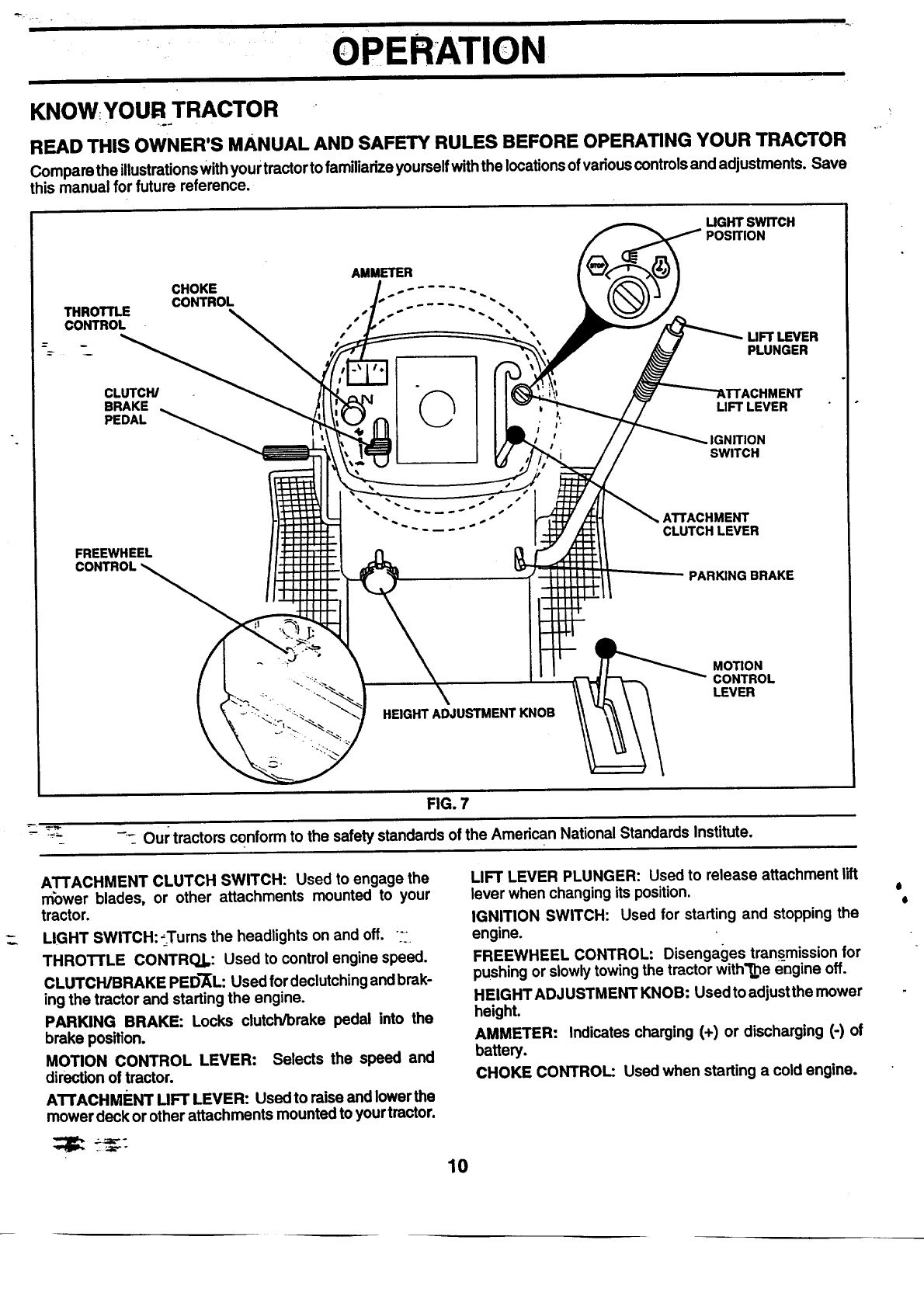
KNOW YOUR TRACTOR
READ THIS OWNER'S MANUAL AND SAFETY RULES BEFORE OPERATING YOUR TRACTOR
Compare the illustrationswith your tractor to familiarizeyourselfwiththe locationsof variouscontrolsand adjustments. Save
this manual for future reference.
AMMETER
CHOKE . - ....
THROTTLE CONTROL _.
CONTROL "" "" • •
----_ D
4-t
CLUTCH/ "0
BRAKE
PEDAL
FREEWHEEL
CONTROL
UGHT SWITCH
LIFT LEVER
PLUNGER
LIFT LEVER
IGNITION
SWITCH
HEIGHT ADJUSTMENT KNOB
PARKING BRAKE
MOTION
CONTROL
LEVER
FIG. 7
_'_ -'- Our tractors conform to the safety standards of the American National Standards Institute.
ATTACHMENT CLUTCH SWITCH: Used to engage the
rr_wer blades, or other attachments mounted to your
tractor.
LIGHT SWITCH: ;Turns the headlights on and off. :.
THROTTLE CONTROJ.: Used to control engine speed.
CLUTCH/BRAKE PED'_L: Used for declutchingand brak-
ing the tractor and starting the engine.
PARKING BRAKE: Locks clutch/brake pedal into the
brake position.
MOTION CONTROL LEVER: Selects the speed and
direction of tractor.
ATTACHMENT UFT LEVER: Used to raise and lowerthe
mower deck or other attachments mounted to your tractor.
10
LIFT LEVER PLUNGER: Used to release attachment lift
lever when changing its position.
IGNITION SWITCH: Used for starting and stopping the
engine.
FREEWHEEL CONTROL: Disengages trans_missionfor
pushing or slowly towingthe tractor with'1_e engine off.
HEIGHT ADJUSTMENT KNOB: Used to adjustthe mower
height.
AMMETER: Indicates charging (+) or discharging (-) of
battery.
CHOKE CONTROL: Used when starting a cold engine.
e
8

OPERATION
The operation of any tractor can result in foreign objects thrown into the eyes, which
can m;esult in severe eye damage. Always wear safety glasses or eye shields while
o_mting your tractor or performing any adjustments or repairs. We recommend awide
vmion safety mask over the spectacles or standard safety glasses.
HOW TO USE YOUR TRACTOR
TO SET PARKING BRAKE (See Fig. 8)
Your tractor isequipped with an operator presence sensing
switch. When engine is running, any attempt by the
operator to leave the seat without first setting the parking
brake will shut off the engine.
•-Depress clutch/brake pedal into full "BRAKE" position
and hold.
•Place parking brake lever in •ENGAGED • position and
release pressurefromclutch/brakepedal. Pedalshould
remain in•BRAKE • position. Make sure parking brake
will hold tractor secure.
ATTACHMENT CLUTCH
THROTTLE SWITCH PULL-OUT TO "ENGAGE"
CONTROL /
CHOKE \ _ /
CONTROL _ _l II_'_._,._/
\"_\_ _/ __,'_ PUSH.INTO .
_/"DISENGAGE
POSmON _',,_'_\" \\\/_ ,,PARKINGBRAKE
OSITION
.)_...,,_ _/r _ MOTION.CONTROL
I"_,"_ '" i LEVER
CLUTCH/BRAKE PEDAL "DISENGAGED"
':DRIVE" POSITION POSITION
FIG. 8
STOPPING (See Fig. 8)
MOWER BLADES -
• Mo--_attachment clutch lever to •DISENGAGED • po-
sition.
GROUND DRIVE -
••Depress clutch/brake pedal intofull •BRAKE •position.
• Move motion control lever to neutral (N) position.
IMPORTANT:_ THE MOTION CONTROL LEVEP_IDOES
NOT RETURN TO NEUTRAL (N) POSITION WHEN THE
CLUTCH/BRAKE P'E_-DALIS DEPRESSED.
ENGINE -
• Move throttle control to slow position.
NOTE: Failure to move throttlecontrolto slow position and
allowing engine to idle before stopping may cause engine
to •backfire•.
•Tum Ignition key to •OFF" position and remove key.
Always remove key when leaving tractor to prevent
unauthodzed use.
N_yer use choke to stop engine.
11
NOTE: Under certain conditions when tractor is standing
idlewiththe engine running,hot engine exhaust gases may
cause =browning" of grass. To eliminate this possibility,
always stop engine when stopping tractor on grass areas.
CAUTION: Always stop tractor com-
pletely, as described above, before leav-
ing the operator's position; to empty
grass catcher, etc.
TO USE THROTTIE CONTROL (See Fig. 8) o
Ak,ays operate engine at full throttle.
•Operating engine at less than full throttle reduces the
battery charging rate.
•Fullthrottle offersthe best bagging and mower perfor-
m_lnce.
"1 USE I;H
I. ct_okecon'
[ _o:use Io,'
•Tc,eng;lge
kr ob in to
"1 IVIOVI"F
(See Fig. 8)
mance.
TO USE CHOKE CONTROL (See Fig. 8)
Use chokecontrolwhenever you are startingacold engine.
Do not use to start a warm engine.
To engage choke control, pull knob out. Slowly push
knob in to disengage.
TO MOVE FORWARD AND BACKWARD
The directionand speed of movement is controlled by the
motioncontrol lever.
•Start tractor with motion control lever in neutral (N)
position.
• Release parking brake and clutch/brake pedal.
•Slowly move motion control lever to desired position.
TO ADJUST MOWER CUTTING HEIGHT (See
Fig. 7)
The cutting height is controlled by tuming the height
adjustment knob in desired direction.
•Turn knob clockwise (F_) to raise cuffing height.
•Turn knob counterclockwise (P-_)to lower cutting
height.
The cuttingheight range is approximately 1-1/2" to 4". The
heights are measured fromthe groundto the blade tipwith
the engine not running. These heigl-Csare approximate
and may vary depending upon soil ce_nditions,height of
grass and types of grass being mowed.
•The average lawn shouldbe cut to approximately2-1/2
inches dudng the cool season and to over 3 inches
during hot months. For healthier and better looking
lawns, mow often and after moderate growth.
•For best cutting performance, grass over 6 inches in
height should be mowed twice. Make the first cut
relatively high; the second to desired height.
OPERATION
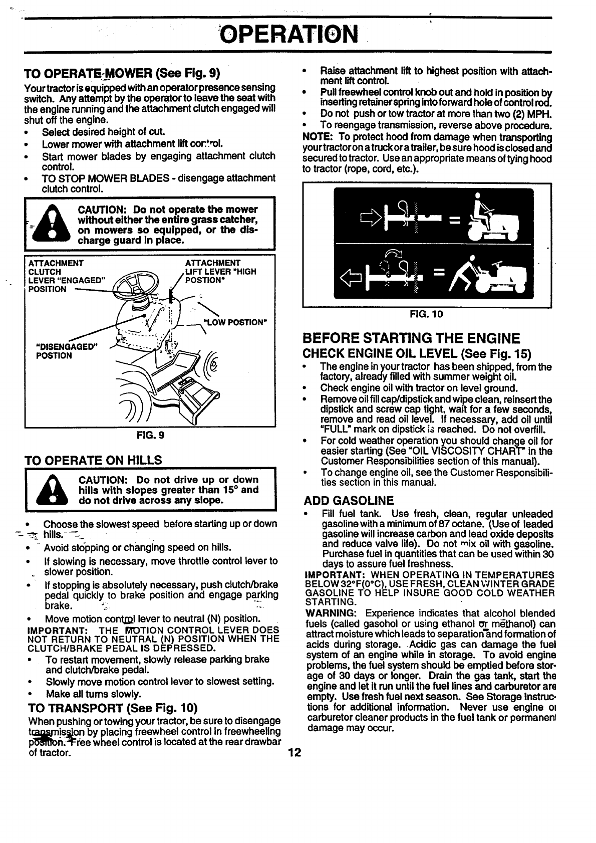
TO OPERATE:_MOWER (See Fig. 9)
Your tractor isequipped withan operator presence sensing
switch. Any attempt by the operator to leave the seat with
the engine running and the attachment clutch engaged will
shut off the engine•
•Select desired height of cut.
•Lower mower with attachment liftcor_ml.
•Start mower blades by engaging attachment clutch
control.
•TO STOP MOWER BLADES -disengage attachment
clutch control.
I_CAUTION: Do not operate the mower
| ALA without either the entire grass catcher,
I--JIMIL on mowers so equlpped, or the dis-
-_1 charge guard in place.
/
FIG. 9
TO OPERATE ON HILLS
i_CAUTION: Do not drive up or down
4Bkhills with slopes greater than 15° and
do not drive across any slope.
_=:3.
Choose the slowest speed before startingup ordown
hills.-'-
Avoid stopping or changing speed on hills.
•if slowing is necessary, move throttle control lever to
_slower position.
•if stopping is absolutely necessary, push clutch/brake
pedal quickly to brake position and engage pa.._ing
brake
•Move motion cont,r.0.1lever to neutral (N) position.
IMPORTANT: THE I_!_TION CONTROL LEVER DOES
NOT RETURN TO NEUTRAL (N) POSITION WHEN THE
CLUTCH/BRAKE PEDAL IS DEPRESSED.
•To restart movement, slowly release parking brake
and clutch/brake pedal.
•Slowly move motion control lever to slowest setting.
•Make all tums slowly.
TO TRANSPORT (See Fig. 10)
When pushing ortowing your tractor, be sure to disengage
t_is_on by placing freewheel control in freewheeling
p'_tton.'_=ree wheel control is located at the rear drawbar
of tractor.
•Raise attachment lift to highest position with attach-
ment liftcontrol.
•Pull freewheel control knob out and hold in positionby
insertingretainerspdngintoforward hole of control rod.
•Do not push or tow tractor at more than two (2) MPH.
•To reengage transmission, reverse above procedure.
NOTE: To protect hood from damage when transporting
your tractoron atruckora trailer, be sure hood isclosed and
secured totractor• Use an appropriate means oftying hood
to tractor (rope, cord, etc.).
FIG. 10
BEFORE STARTING THE ENGINE
CHECK ENGINE OIL LEVEL (See Fig. 15)
•The engine inyourtractor has been shipped, from the
factory, already filled with summer weight oil.
•Check engine oil with tractor on level ground.
•Remove oil fill cap/dipstickand wipe clean, reinsertthe
dipstick and screw cap tight, wantfor afew seconds,
remove and read oil level. If necessary, add oil until
"FULL" mark on dipsticki_ reached. Do not overfill.
•For cold weather operation you should change oil for
easier starting (See =OIL VISCOSITY CHART" in the
Customer Responsibilitiessection of this manual).
•To change engine oil,see the Customer Responsibili-
ties section in this manual.
ADD GASOLINE
•Fill fuel tank. Use fresh, clean, regular unleaded
gasoline witha minimumof 87 octane. (Use of leaded
gasoline will increase carbon and lead oxide deposits
and reduce valve life). Do not mix oil with gasoline.
Purchase fuel inquantities that can be used within 30
days to assure fuel freshness.
IMPORTANT: WHEN OPERATING IN TEMPERATURES
BELOW 32°F(0°C), USE FRESH, CLEAN WINTER GRADE
GASOLINE TO HELP INSURE GOOD COLD WEATHER
STARTING.
WARNING: Experience indicates that alcohol blended
fuels (called gasohol or using ethanol o1"m_thanol) can
attract moisturewhich leads to separation-and formation of
acids during storage. Acidic gas can damage the fuel
system of an engine while in storage. To avoid engine
problems, the fuel system should be emptied before stop
age of 30 days or longer. Drain the gas tank, start the
engine and let it run untilthe fuel lines and carburetor are
empty. Use fresh fuel next season. See Storage Instruc-
tions for additional information. Never use engine ol
carburetor cleaner products in the fuel tank or permanenl
damage may occur.
12
OPERATION
I& CAUTION: Fill to bottom of gas tank I
fill6i' neck. Do not overfill..Wipe off any I
•spilled oil or fuel. Do not store, spill or
use gasoline near an open flame.
TO START ENGINE (See Fig. 8)
When starting the engine for the firsttime or if the engine
has run out of fuel, it will take extra cranking time to move
fuel from the tank to the engine.
•Be sure freewheel control is in the transmission en-
gaged position.
•Sit on seat in operating position, depress clutch/brake
pedal and set parking brake.
":Place motion control lever in neutral (N) position.
Move attachment clutch to =DISENGAGED • position.
Move throttle control to fast position
Pull choke control out for a cold engine start attempt.
For a warm engine start attempt the choke control may
not be needed.
NOTE: Before starting, read the warm and cold starting
procedures below.
•Insertkeyinto ignitionandturnkeyclockwiseto =START"
positionand release key as soon as engine starts. Do
not run starter continuously for more than fifteen sec-
onds per minute. If the engine does not start after
several attempts, push choke control in, wait a few
minutes and try again. Ifengine stilldoes notstart, pull
the choke control out and retry.
WARM WEATHER STARTING (50° F and above)
• When engine, starts,,slowi,vpush choke control in until
the engine begins to run smoothly. If the engine starts
to run roughly, pull the choke control out slightly for a
few seconds and then continue to push the control in
slowly.
•The attachments and grounddrive can nowbe used. If
the engine does not accept the load, restartthe engine
and allow itto warm up for one minute usingthe choke
as described above.
COLD WEATHER STARTING (50° F and below)
•When engine starts, slowly push choke control in until
the engine begins to run smoothly. Continue to push
the-_oke control in small steps allowing the engine to
accept small changes in speed and load, until the
choke control is fully in. If the engine starts to run
roughly, pull the choke control out slightly for a few
seconds and then continue to push the control in
slowly. This may require an engine warm-up period
from several seconds to several minutes, depending
on the tem_perature. '_.
AUTOMATIC TRAN.LSMISSlON WARM UP
• Before driving fife unit incold weather, the transmis-
sion should be warmed up as follows:
• Be sure the tractor is on level ground.
•Place the motion control lever in neutral.
Release the parking brake and let the clutch/brake
slowly retum to operating position.
•Allow one minute for transmission to warm up.
This can be done during the engine warm up
period.
The attachments can be used duringthe engine warm-
: Ul_l_eriodafter the transmission has been warmed up
and may require the choke controlbe pulledoutslightly. 13
NOTE: If at a high altitude (above 3000 feet) or in cold
temperatures (below 32 F)the carburetor fuel mixture may
need to be adjusted forbest engine performance. See '1"O
ADJUST CARBURETOR" inthe Service and Adjustments
section of this manual.
PURGE TRANSMISSION
CAUTION: Never engage or disengage
freewheel lever while the engine is run-
ning.
To ensure proper operation and performance, it is recom-
mended that the transmission be purged before operating
tractor for the first time. This procedure will remove any
trapped air inside the transmission which may have devel-
oped during shipping of your tractor.
IMPORTANT: SHOULD YOUR TRANSMISSION REQUI'RE
REMOVAL FOR SERVICE OR REPLACEMENT, I:r
SHOULD BE PURGED AFTER REINSTALLATION
BEFORE OPERATING THE TRACTOR.
•Place tractorsafely onlevel surface with engine off and
parking brake set.
•Disengage transmission by placing freewheel control
in freewheeling position (See =TO TRANSPORT" in
this section of manual).
•Sitting inthe tractor seat, start engine. After the eng!ne
is running, move throttle control to slow position. With
motion control lever in neutral (N) position, slowly
disengage clutch/brake pedal.
•Move motion control lever to full forward position and
hold for five (5) seconds. Move lever to full reverse
position and hold for five (5) seconds. Repeat this
procedure three (3) times.
NOTE: During this procedure there will be no movement of
drive wheels. The air is being removed from hydraulicdrive
system.
•Muve motion controlleverto neutral (N) position. Shut-
off engine and set parking brake.
•Engage transmission by placing freewheel control in
drivingposition(See =TOTRANSPORT" inthissection
of manual).
•Sittinginthetractor seat, start engine. Afterthe engine
is running, move throttle control to half (1/2) speed.
With motioncontrol lever in neutral (N) position, slowly
disengage clutch/brake pedal.
•Slowly move motion control lever forward, after the
tractor moves approximately five (5) feet, slowly move
motion control lever to reverse position. After the
tractor moves approximately five (5) feet retum the
motioncontrol lever to the neutralLN)position. Repeat
this procedure with the motion co=trol lever three (3)
times.
•Your tractor is now purged and now ready for normal
operation.

OPERATION
MOWING T S.
• Tire chains cannot be used when the mower housing
is attached to tractor.
•Mower should be properly leveled for best mowing
performance. See "TO LEVEL MOWER HOUSING" in
the Service and Adjustments section of this manual.
•The left hand side of mower should be used for trim-
ming.
•Drive so that clippings are discharged onto the area
that has been cut. Have the cut area to the rightof the
machine. This will result in a more even distributionof
clippings and more uniform cutting.
•When mowing large areas, start by turning to the right
---- so---thatclippings will discharge away from shrubs,
fences, driveways, etc. After one or two rounds,mow
in the opposite direction making left hand tums until
finished (See Fig. 11).
•If grass is extremely tall, it should be mowed twice to
reduce load and possible fire hazard from dried clip-
pings. Make first cut reiatively high; the second to the
desired height.
•Do not mow grass when it is wet. Wet grass will plug
mower and leave undesirable clumps. Allow grass to
dry before mowing.
•Always operate engine at full throttlewhen mowing to
assure better mowing performance and proper dis-
charge of material. Regulate ground speed by select-
ing a low enough gear to give the mower cutting
performance as well as the quality of cut desired.
•When operating attachments, select a ground speed
that will suit the terrain and give best performance of
the attachment being used.
iI
MULCHING MOWING TIPS
IMPORTANT: FOR BEST PERFORMANCE, KEEP
MOWER HOUSING FREE OF BUILT-UP GRASS AND
TRASH. CLEAN AFTER EACH USE.
The special mulching blade will recut the grass clip-
pings many times and reduce them in size so that as
they fall onto the lawn they will disperse into the grass
and not be noticed. Also, the mulched grass will
biodegrade quickly to provide nutrients for the lawn.
Always mulch with your highest engine (blade) speed
as this will provide the best recutting action of the
blades.
•Avoidcuttingyour lawnwhen it iswet. Wet grasstends
to form clumps and interfereswith the mulchingaction.
The bast time to mow your lawn is the early afternoon.
At this time the grasshas dried and the newly cut area
will not be exposed to the direct sun.
•Forbest results,adjustthe mower cuttingheightso that
the mower cuts off only the top one-third of the grass °
blades (See Fig. 12). For extremely heavy mulching,
reduce your widthof cuton each pass and mow slowly.
•Certain types of grass and grass conditions may re-
quire that an area be mulched a second time to com-
pletely hide the clippings. When doing asecond cut,
mow across or perpendicular to the first cut path.
•Change your cuttingpattern from week to week. Mow
northto southoneweek then change to east towest the
next week. This willhelp prevent matting and graining
of the lawn.
MAX 1/3
_FIG. 11
FIG. 12
14
'CUSTOMERRESPONSIBILITIES
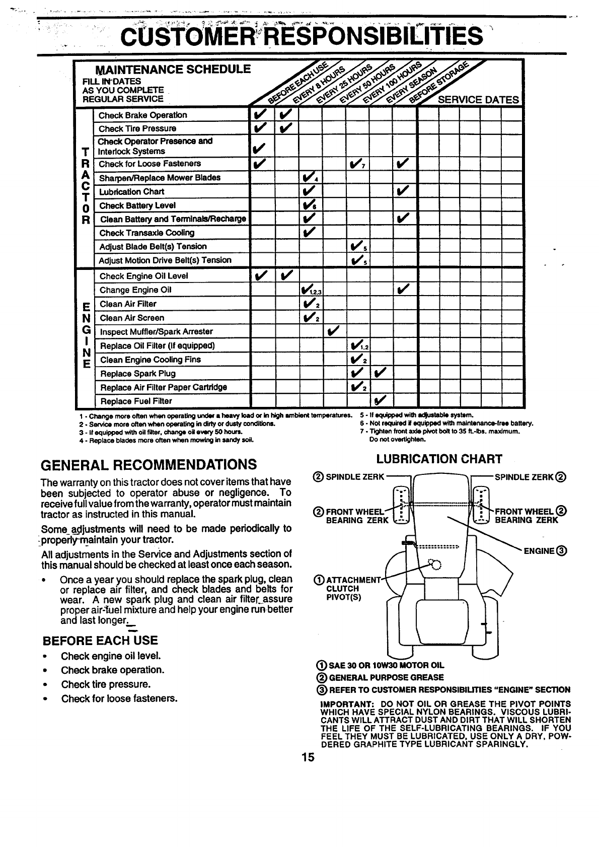
Check Brake Operation V' V'
Check Tire Pressure _
Check Operator Presence and
T Interlock Systems _V'
Check for Loose Fasteners V'7 V'
A Sharpen/Rep lace M°wer Blades _'=
TLubrication Chart V'
Check Battery Level V_6
Clean Battery and Terminals/Recharge V' V'
Check Transexle Cooling i ll_
Adjust Blade Belt(s) Tension V's
Adjust Motion Drive Belt(s) Tension I,i's
Check Engine Oil Level V'
Change Engine Oil V_1.2.3 Vp
E Clean Air Filter V'=
Clean Air Screen V'2
(_ Inspect Muffler/Spark Arrester Vr
Replace Oil Filter (If equipped) I_.,
N Clean Engine Cooling Fins if2
Replace Spark Plug V' V_
Replace Air Filter Paper Cartridge V'2
Replace Fuel Filter _/
1 - Change more often when operating under a heavy load _in high ambient temperatures. 5 - If equipped with adjustable system.
2 - Service more often when operating in dirty ordusty conditions. 6 - Not required if equipped wi_ maintenance-free battery.
3 - If equipped with oil filter, change oll every 50 hours. 7 - Tighten front axle pivot bolt to 35 ft.-Ibs, maximum.
4-Replace blades more often when mowing in sandy soiL Do notovertighten.
GENERAL RECOMMENDATIONS
The warranty on this tractor does notcover items that have
been subjected to operator abuse or negligence. To
receive full value from the warranty, operator must maintain
tractor as instructed in this manual.
Some adjustments will need to be made periodically to
ipropedy-rnaintain your tractor.
All adjustments in the Service and Adjustments section of
this manual should be checked at least once each season.
•Once a year you should replace the spark plug, clean
or replace air filter, and check blades and belts for
wear. A new spark plug and clean air filter.assure
proper air-'fuelmixture and help your engine runbetter
and last longer:...
BEFORE EACH USE
• Check engine oil level.
•Check brake operation.
•Check tire pressure.
• Check for loose fasteners.
15
LUBRICATION CHART
(_t SPINDLE ZERK ---------I_(_-'-"_ _1"-'_ SPINDLE ZERK (_)
(_l FRONT WHEEL'_.'_"_--'-- ..... __'Jr" FRONT WHEEL (_)
BEARING ZERK "t_..:_ll_ ..... "_ BEARING ZERK
(_ SAE 30 OR 10W30 MOTOR OIL
(_ GENERAL PURPOSE GREASE
(_) REFER TO CUSTOMER RESPONSIBILmES "ENGINE" SECTION
IMPORTANT: DO NOT OIL OR GREASE THE PIVOT POINTS
WHICH HAVE SPECIAL NYLON BEARINGS. VISCOUS LUBRI-
CANTS WILL ATTRACT DUST AND DIRT THAT WILL SHORTEN
THE LIFE OF THE SELF-LUBRICATING BEARINGS. IF YOU
FEEL THEY MUST BE LUBRICATED, USE ONLY A DRY, POW-
DERED GRAPHITE TYPE LUBRICANT SPARINGLY.

L
TRACTOR ....
Always observe safe_ _rules when performing any mainte-
nance.
i
;CUSTOMERi. RESPONSIBILITIES
II
BRAKE OPERATION
If tractor requires more than six (6) feet stopping distance
at high speed inhighest gear, then brake must be adjusted.
(See "TO ADJUST BRAKE" in the Service and Adjust-
ments section of this manual).
TIRES
• Maintain proper air pre,s,surein all tires (See =PROD-
UCT SPECIFICATIONS on page 3 of this manual).
• =:,Keep_tiresfree of gasoline, oil, or insectcontrol chemi-
cals which can harm rubber.
•Avoid stumps, stones, deep ruts,_sharp objects and
other hazards that may cause tire damage.
NOTE: To seal tire punctures and prevent flat tires due to
"- slow leaks, tire sealant may be purchased from your local
parts dealer. Tire sealant also prevents tire dry rot and
corrosion.
BLADE CARE
For best results mower blades must be kept sharp. Re-
place bent or damaged blades.
BLADE REMOVAL (See Fig. 13)
• Raise mower to highest position to allow access to
blades.
Remove hex bolt, lockwasher and flat washer securing
blade.
Install new or resharpened blade with trailing edge up
towards deck as shown.
IMPORTANT: TO ENSURE PROPER ASSEMBLY,
CENTER HOLE IN BALDE MUST ALIGN WaTH STAR ON
MANDREL ASSEMBLY.
• Reassemble hex bolt, lock washer and flat washer in
exact order as shown,
_EX BOLT (GRADE 8)°
•Tighten bolt securely (27-35 Ft. Lbs, torque).
_IMEORTAN.T-: BLADE BOLT IS GRADE 8 HEATTREATED.
-N61[e: We dohot recomme_ndsharpening blade - but ifyou
do, be sure the blade is balanced.
MANDREL ASSEMBLY
TRAILING EDGE UP
BLADE
_CENTER HOLE
FLAT WASH! R
/_LOCK WASHER '_ I\ "_
•TO SHARPEN BLADE (See Fig. 14)
Care should be taken to keep the blade balanced. An
unbalanced blade willcause excessive vibration and even-
tual damage to mower and engine.
•The blade can be sharpened with a file or on a grinding
wheel. Do notattempt to sharpen while on the mower.
•To check blade balance, you will need a 5/8" diameter
steel bolt, pin,or a cone balancer. (When usinga cone
balancer, follow the instructions supplied with bal-
ancer).
•Slide blade onto an unthreaded portionof the steel bolt
or pin and holdthe bolt or pin parallel with the ground.
If blade is balanced, it should remain in a horizontal
position. If either end of the blade moves downward,
sharpen the heavy end untilthe blade is balanced.
NOTE: Do not use a nailfor balancing blade. The lobes of
the center hole may appear to be'centered, but are not.
*A GRADE 8 HEAT TREATED BOLT CAN BE
-_IlJIENTIRED BY SIX UNES ON THE BOLT HEAD.
FIG. 13
CENTER HOLE //
5/8" BoLT__ __ BLADE
ORF,l i
FIG. 14
BATTERY
Your tractor has a battery charging system which is suffi-
cient for normal use. However, periodic charging of the
battery with _n automotive charger will extend its life.
•Keep battery and terminals clean.
•Keep battery boltstight.
••Keep small vent holes open.
•Recharge at 6-10 amperes for I hour.
TO CLEAN BATTERY AND TERMINALS
Corrosion and dirton the battery and terminals can cause
the battery to =leak"power.
• Remove terminal guard.
•Disconnect BLACK batten/ cable first then RED
battery cable and remove battery from tractor.
•Rinse the battery with plain water and dry:
•Clean terminals andbatterycable ends=withwire brush
until bright.
•Coat terminals with grease or petroleum jelly.
•Reinstall battery (See "CONNECT BATTERY' in the
Assembly section of this manual).
16

iiii
CBSTOMER RESPONSIBILITIES
V-BELTS
Check V-belts fb'rdeterioration and wear after 100 hoursof
operation and replace if necessary, 1"he belts are not
adjustable. Replace belts if they begin to slip from wear.
TRANSAXLE COOLING
The fan and cooling fins of transmission should be kept
clean to assure proper cooling.
Do not attempt to clean fan or transmission while engine is
running or while the transmission is hot.
•Inspect coolingfan to be sure fan blades are intact and
clean.
Inspect cooling fins for dirt, grass clippings and other
7-matedals. To prevent damage to seals, do not use
compressed air or high pressure sprayer to clean
cooling fins.
TRANSAXLE PUMP FLUID
The transaxle was sealed at the factory and fluid mainte-
nance is notrequired for the lifeof the transaxle. Should the
transaxle ever leak or require servicing, contact your near-
est authorized service center/department.
ENGINE
LUBRICATION
Only use high quality detergent oil rated with API service
classification SF, SG or SH. Select the oil's SAE viscosity
grade according to your expected operating temperature.
SAE VISCOSITY GRADES
*F -20" 0, 30" 32" 40" 60, 80" 100"
°c _-_ -lo" o- 10" _ _ _-
T_P_TURE _'_GE_rncIF'ATEOeEFORe,t_"O,.C._QS
" Air cooled engine/run hotter than automotive engine. Use of multi-vtsco¢,_o_s
(10W-30_et_)a=b_t_" 40"F(4"C)willresultInhighoil¢onstaq)Uonandposs_kD
engl_-_age, che_ o_kwe!morefrequenUyUes_gZheestypesofoh.
- "SAE 30 oll, tf used below 40"F(4°C)__will result in hard star_ and possible engine
born damage due to inadequate lubrication.
TO CHANGE ENGINE OIL (See Fig. 15)
Determine temperature range expected before oil change.
All oil must meet API service classification SF, SG or SH.
•Be sure tractor is on level surface.
•Oil will drain more freely when warm.
•Catch oil in a suitable container.
•Remove oil fillcap/dipstick. Be careful notto allow dirt
to enter the engine when changing oil.
•Remove drain plug.
•After oil has drained completely, replace oil drain plug
and tighten securely.
•Refill engine with oil through oil fill dipstick tube. Pour
slowly. Do not overfill. For approximate capacity see
=PRODUCT SPECIFICATIONS" on page 2 of this
manual. °
•Use gauge on oilfill cap/dipstickforchecking level. Be
sure dipstick cap is tightened securely for acc'urat_
reading. Keep oil at =FULL" line on dipstick.
AIR SCREEN
OIL RLL CAW
DIPSTSICK
OIL DRAIN
PLUG
FIG. 15
Change the oil after every 50 hours of operation or at least
once a year if the tractor is not used for 50 hours in one year.
Check the crankcase oil level before starting the.engine
and after each eight (8) hours of operation. Tight_n oil fill
cap/dipstick secure_ each time you check the oil level.
17

"CUSTOMERRESPONSIBILITIES
AIR FILTER (See Fig. 16)
Your engine will fibt run properly using a dirty air filter.
Clean the foam pre-cleaner after every 25 hours of opera-
tion or every season. Service paper cartridge every 100
hours of operation orevery season, whichever occursfirst.
Service air cleaner more often under dusty conditions.
•Remove knobs and cover.
TO SERVICE PRE-CLEANER
•Wash it in liquid detergent and water.
•Squeeze it dry in a clean cloth.
•Saturate it in engine oil. Wrap it in clean, absorbent
cloth and squeeze to remove excess oil.
-= If_ery dirty or damaged, replace pre-cleaner.
TO SERVICE CARTRIDGE
•Clean cartridge by tapping gently on flat surface. Ifvery
dirty or damaged, replace cartridge.
•Reinstall precleaner cartridge cover and secure with
knobs.
IMPORTANT: PETROLEUM SOLVENTS, SUCH AS
KEROSENE, ARE NOT TO BE USED TO CLEAN THE
CARTRIDGE. THEY MAY CAUSE DETERIORATION OF
THE CARTRIDGE. DO NOT OIL CARTRIDGE. DO NOT
USE PRESSURIZED AIR TO CLEAN OR DRY
CARTRIDGE.
KNOB _COVER
CARTRIDGE
FIG. 16
CLEAN AIR SCREEN (See Fig. 17)
Air screen must be kept free of dirt and chaff to prevent
engine damage fromoverheating. Clean with a wire brush
or compressed airto remove dirt and stubborn dried gum
fibers.
AIR SCREEN
FIG. 17
CLEAN AIR INTAKF.JCOOLING AREAS
To insure proper cooling, make sure the grass screen,
coolingfins, and other external surfaces of the engine are
kept clean at all times.
Every 100 hoursof operation (more often under extremely
dusty, dirty conditions), remove the blower housing and
other coolingshrouds. Clean the cooling fins and external
surfaces as necessary. Make sure the coolingshrouds are
reinstalled.
NOTE: Operating the engine with a blocked grass screen,
dirty or plugged cooling fins, and/or cooling shrouds re-
moved will cause engine damage due to overheating.
MUFFLER
Inspect and replace corrodedmuffler and spark arrester (if
equipped) as it could create a fire hazard and/or damage.
SPARK PLUGS
Replace spark plugs at the beginning of each mowing
season or after every 100 hours of operation, whichever
occurs first. Spark plugtype and gap setting are shown in
=PRODUCT SPECIFICATIONS" on page 2 of this manual.
18

......CUSTOMER'RESPONSIBILITIES
ENGINE OIL-RLTER (See Fig. 18)
Replace the engine oil filter every season or every other oil
change if the tractor is used*more than 100 hours m one
year.
•Unscrew old filter by turning counterclockwise. Use a
suitable container to catch oil.
•Applya thin coating of new engine oil to rubber gasket
on replacement oil filter.
•Install replacement oil filter by tuming clockwise until
rubber gasket contacts mounting surface, then tighten
filter an additional 1/2 to 3/4 tum.
Fill crankca..sewith new oil (See "TO CHANGE EN-
GINE OIL inthis section of this manual). For approxi-
-mate capacity see =PRODUCT SPECIFICATIONS •on
page 3 of this manual.
•Start engine and check foroil leaks. Correct any leaks
before placing engine into full operation.
IN-LINE FUEL FILTER (See Fig. 19)
The fuel filter should be replaced once each season, fffuel
filter becomes clogged, obstructingfuel flow to carburetor,
replacement is required.
•With engine cool, remove filter and plug fuel line
sections.
•Place new fuel filter in position it, :uel line with arrow
pointing towards carburetor.
•Be sure there are no fuel line leaks and clamps are
properly positioned.
•Immediately wipe up any spilled gasoline.
CLAMP CLAMP
OIL RLTER
'0
FIG. 18
FUEL
FILTER
FIG. 19
CLEANING
•Clean engine, battery, seat, finish, etc. of all foreign
matter.
•Keep finished surfacesand wheels free of all gasoline,
oil, etc.
•Protect painted surfaces with automotive type wax.
We do not recommend using a garden hose to clean your
tractor unless the electrical system, muffler, air filter and
carburetor are covered to keep water out. Water in engine
can result in a shortened engine life.
19

ERVIG AN D USTMENTS
CAU:FION: BEFORE PERI:ORMING ANY SERVICE OR ADJUSTMENTS:
•Depress clutch/brake pedal fully and set parking brake.
•Place motion control lever in neutral (N) position.
•Place attachment clutch in =DISENGAGED" position.
•Turn ignition key "OFF" and remove key.
•Make sure the blades and all moving parts have completely stopped.
•Disconnect spark plug wire from spark plug and place wire where it cannot come in contact with
plug.
TRACTOR
TO REMOVE MOWER (See Fig. 20)
M_ower willbe easier to remove fromthe rightsideof tractor.
• Place attachment clutch in "DISENGAGED" position.
•Move attachment liftlever forward to lower mower to its
lowest position.
•Roll belt off engine pulley,
•Disconnect clutch rod from clutch lever by removing
retainer spring.
•Disconnect anti-sway, bar from Chassis bracket by
removing retainer spnng.
• Disconnect suspension arms from rear deck brackets
by removing retainer springs.
•Disconnect front linksfrom deck by removing retainer
springs.
•Raise lift lever to raise suspension arms. Slide mower
out from under tractor.
IMPORTANT: IF AN ATTACHMENT OTHER THAN THE
MOWER DECK IS TO BE MOUNTED ON THE TRACTOR,
REMOVE THE FRONT LINKS.
TO INSTALL MOWER (See Fig. 20)
•Raise attachment lift lever to its highest position.
•Slide mower under tractorwith discharge guard to right
side of tractor.
•Lower lift lever to its lowest position.
•Install mower in reverse order of removal instructions.
CLUTCH LEVER
CLUTCHI
SUSPENSION
ARMS
RETAINER
SPRING
AN_-SWAY BAR RET_NER SPRINGS
(BOTH SIDES)
FIG. 20
2O

s c' ERVi E!AND; ADJUSTMENTS
r- !
TO LEVEL MOWER HOUSING
Adjust the m0T_ser Whiletractor isparked on levelground or
driveway. Make sure tires are properly inflated (See
=PRODUCT SPECIFICATIONS" on page 2 ofthismanual).
If tires are over or underinflated, you willnot properlyadjust
your mower.
SIDE-TO-SIDE ADJUSTMENT (See Figs. 21 and 22)
•Raise mower to its highest position.
•At the midpointof both sides of mower, measure height
frombottom edge of mower to ground. Distance"A"on
both sides of mower should be the same orwithin 1/4"
of each other.
•If adjustment is necessary, make adjustment on one
_side of mower only.
•To raise one side of mower, tighten liftlink adjustment
nut on that side.
•To lower one side of mower, loosen liftlinkadjustment
nut on that side.
NOTE: Three full turns of adjustment nut will change
mower height about 1/8".
•Recheck measurements after adjusting.
BOTTOM EDGE BOTTOM EDGE
OF MOWER TO OF MOWER TO
FIG. 21
SUSPENSION ARM
_UNK
ADJUSTMENT NUT
FIG. 22
FRONT-TO-BACK ADJUSTMENT (See Rgs. 23 and 24)
IMPORTANT: DECK MUST BE LEVEL SIDE-TO-SIDE. IF
THE FOLLOWING FRONT-TO-BACK ADJUSTMENT IS
NECESSARY, BE SURE TO ADJUST BOTH FRONT LINKS
EQUALLY SO MOWER WILL STAY LEVEL SIDE-TO-
SIDE.
To obtain the best cutting results, the mower housing
should be adjustedso that the front isapproximately 1/8" to
1/2" lower than the rear when the mower is in its highest
position.
Check adjustment on right side of tractor. Measure dis-
tance "D"directlyinfrontand behind the mandrel at bottom
edge of mower housing as shown.
•Before makingany necessary adjustments, checkthat
bothfront linksare equal inlength. Bothlinks shouldbe
approximately 10-3/8".
•If links are not equal in length, adjust one link to sa.rne
length as other link.
•To lower front of mower loosen nut "E" on both'fror_t
links an equal number of turns.
•When distance =D" is 1/8" to 1/2" lower at front than
rear, tighten nuts "F" against trunnion on both front
links.
•To raisefrontof mower, loosen nut"F_fromtrunnion on
both front links.Tighten nut "E" on both front links an
equal number of turns.
•When distance "D" is 1/8" to 1/2" lower at front than
rear, tightennut"F"against trunnionon bothfront links.
Recheck side-to-side adjustment.
o ot MANDREL
"D"
FIG. 23
BOTH FRONT MNKS MUST BE EQUAL IN LENGTH
NUT
NUT "E"
FRONT UNKS TRUNNION
21 FIG. 24

SERVlCEi;AN D ADJ USTMENTS
TO REPLACE MOWER BLADE DRIVE BELT
(See Fig. 25)::_
The mower blade drive belt may be replaced withouttools.
Park the tractor on level surface, Engage parking brake.
BELT REMOVAL -
• Remove mower from tractor (See "TO REMOVE
MOWER • in this section of this manual).
• Work belt off both mandrel pulleys and idler pulleys.
• Pull belt away from mower.
BELT INSTALLATION -
•Install new belt in reverse order of removal.
•Make sure belt isinall pulley grooves and insideall belt
guides.
- Install mower in reverse order of removal instructions.
-- w
MANDREL
PULLEY_ iDLER
PULLEYS
MANDREL
PULLEY
FIG. 25
WITH PARKINGBRAKE "ENGAGED"
NUT"A"
"_i _, ARM
DO NOT TOUCH THIS NUT. IF FURTHER
BRAKE ADJUSTMENT IS NECESSARY
CONTACT YOUR NEAREST AUTHORIZED
SERVICE CENTER/DEPARTMENT
FIG. 26
TO REPLACE MOTION DRIVE BELT
(See Fig. X)
Park the tractor on level surface. Engage parking brake.
For assistance, there is a belt installation guide decal on
bottom side of left footrest.
•Remove mower (See "TO REMOVE MOWER" in this
section of this manual.)
•Remove belt from stationary idler and clutching idler.
•Pull belt slack toward rear of tractor. Carefully remove
belt upwards from transmission input pulley and over
cooling fan blades.
•Pull belt toward front of tractor and remove downward
from around engine pulley.
•Install new belt by reversing above procedure.
TO ADJUST BRAKE (See Fig. 26)
Your tractor is equipped with an adjustable brake system
which is mounted on the side of the transaxle.
If tractor requires more than six (6) feet stopping distance
- at'highspe_'d.inhighest gear, .thenbrake must be adjusted.
•-Depressclutch/brake pedal and engage parkingbrake.
•Measure distance between brake operating arm and
nut "A"on brake rod.
If distance is other than 1-9/16", loosen jam nut and
turn nut"A" un=tildistance becomes 1-9/16". Retighten
jam nut agair_st nut "A". -
Road test tractor fo_,_)roperstopping distance as stated
above. Readjust if-necessary. If stopping distance is
still greater than six (6) feet in highest gear, further
maintenance is necessary. Contact your nearest au-
thorized service center/department.
FIG. 27
22
...............oi SERVICEANDADJUSTMENTS
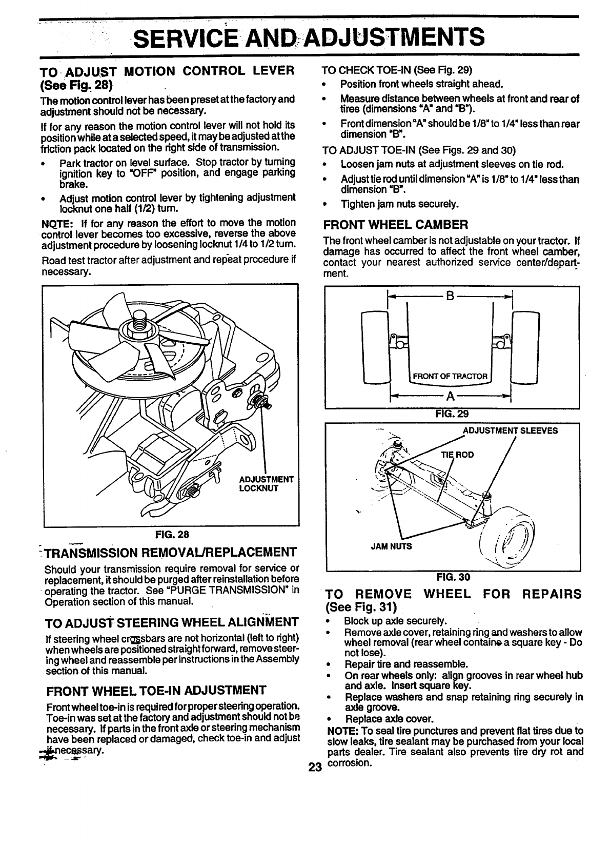
TO ADJUST MOTION CONTROL LEVER
(See Fig. 28)
The motion control lever has been preset atthe factory and
adjustment should not be necessary.
If for any reason the motion control lever will not hold its
positionwhile at a selected speed, it may be adjusted at the
fdction pack located on the right side of transmission.
•Park tractor on level surface. Stop tractor by tuming
ignition key to "OFF" position, and engage parking
brake.
•Adjust motion control lever by tightening adjustment
Iocknut one half (1/2) turn.
NOTE: If for any reason the effort to move the motion
control lever becomes too excessive, reverse the above
adjustment procedure by loosening Iocknut 1/4 to 1/2 turn.
Road test tractor after adjustment and repeat procedure if
necessary.
ADJUSTMENT
LOCKNUT
FIG. 28
_TRAN-SMISSION REMOVAL/REPLACEMENT
Should your transmission require removal for service or
replacement, itshould be purged after reinstallationbefore
operating the tractor. See =PURGE TRANSMISSION" in
Operation section of this manual.
TO ADJUST STEERING WHEEL ALIGNMENT
If steering wheel crg_sbars are not horizontal(left to right)
when wheels are positionedstraightforward, removesteer-
ing wheel and reassemble per instructionsinthe Assembly
section of this manual.
FRONT WHEEL TOE-IN ADJUSTMENT
Frontwheel toe-in isrequired forproper steeringoperation.
Toe-in was set at the factory and adjustmentshould notbe
necessary, if parts inthe front axle or steering mechanism
have been replaced or damaged, check toe-in and adjust
-_-nec=lbssary.
TO CHECK TOE-IN (See Fig. 29)
•Position front wheels straight ahead.
•Measure distance between wheels at front and rear of
tires (dimensions "A" and "B").
•Frontdimension=A"shouldbe 118"to 1/4"lessthan rear
dimension =B'.
TO ADJUST TOE-IN (See Figs. 29 and 30)
•Loosen jam nuts at adjustment sleeves on tie rod.
•Adjusttie rod untildimension =A"is 1/8" to 114"less than
dimension =B_.
•Tighten jam nuts securely.
FRONT WHEEL CAMBER
The front wheel camber is not adjustable on your tractor. If
damage has occurred to affect the front wheel camber,
contact your nearest authorized service center/depart,
ment.
B
A
FIG. 29
TO REMOVE WHEEL FOR REPAIRS
(See Fig. 31)
•Block up axle securely.
•Remove axle cover, retaining ringa,ndwashers to allow
wheel removal (rear wheel contain_ a square key -Do
not lose).
•Repair tire and reassemble.
•On rear wheels only: align grooves in rear wheel hub
and axle. Insert square key.
•Replace washers and snap retaining ring securely in
axle groove.
•Replace axle cover.
NOTE: To seal tire punctures and prevent flat tires due to
slow leaks, tire sealant may be purchased from your local
parts dealer. Tire sealant also prevents tire dry rot and
23 corrosion.

S ERVI Nb ;ADj UST MENTS
IERS
RETAINING
RING
°
AXLE COVER
-- - FIG. 31
TO START ENGINE WITH A WEAK BATTERY
(See Fig. 32)
CAUTION: Lead-acid batteries gener-
ate explosive gases. Keep sparks, flame
and smoking materials away from bat-
teries. Always wear eye protection
when around batteries.
If your battery is too weak to start the engine, it should be
recharged. If "jumper cables• are used for emergency
starting, follow this procedure:
IMPORTANT: YOUR TRACTOR IS EQUIPPED WITH A 12
VOLT NEGATIVE GROUNDED SYSTEM. THE OTHER
VEHICLE MUST ALSO BE A12 VOLT NEGATIVE
GROUNDED SYSTEM. DO NOT USE YOUR TRACTOR
BATTERY TO START OTHER VEHICLES.
TO A'I-rACH JUMPER CABLES -
•Connect each end of the RED cable to the POSITIVE
(+) terminal of each battery, taking care not to short
against chassis.
•Connect one end of the BLACK cable to the NEGA-
TIVE (-) terminal of fully charged battery.
•Connect the other end of the BLACK cable to good
CHASSIS GROUND, away fromfuel tank and battery.
~ TO REMOVE CABLES, REVERSE ORDER -
•"'- BLACK-_.ablefirst from chassis and then from the fully
charged battery.
•RED cable last from both batteries.
"POSITIVE" (+)
LH. PANEL
BOLT
"NEGATIVE" (-)
FIG. 32
TO REPLACE HEADLIGHT BULB
•Raise hood.
•Pull bulb holder out of the hole in the backside of the
grill.
•Replace bulb in holder and push bulb holder securely
back into the hole in the backside of the grill.
•Close hood.
INTERLOCKS AND RELAYS
Loose or damaged wiring may cause your tractor to run
poorly, stop running, or prevent it from starting.
•Check wiring. See electrical wiring diagram in the
Repair Parts section of this mar.ual.
TO REPLACE FUSE
Replace with 30 amp automotive-type plug-in fuse. The
fuse holder is located behind the dash.
TO REMOVE HOOD AND GRILL ASSEMBLY
(See Fig. 33)
•Raise hood.
• Unsnap headlightwire connector.
• Standinfrontoftractor. Grasphoodatsides, tilttoward
engine and lift off of tractor.
•To replace, reverse above procedure.
24

SERVICE ANDADJUSTMENTS
HOOD
HEADUGHT
WIRE
CONNECTOR
FIG. 33
ENGINE
TO ADJUST THROTTLE CONTROL CABLE
(See Fig. 34)
The throttle control has been preset at the factory and
adjustment should notbe necessary. Checkadjustment as
described below before loosening cable. If adjustment is
necessary, proceed as follows:
•With engine notrunning, move throttle control lever to
fast position.
•Check that swivel is against stop. If it is not, loosen
cable clamp screw and pull cable back until swivel is
against stop. Tighten cable clamp screw securely.
TO ADJUST CHOKE CONTROL (See Fig. 35)
The choke control has been preset at the factory and
adjustment should not be necessary. Check adjustment as
described below before loosening cable. If adjustment is
._necessa_'y, proceed as follows:
....•With-engine not running, move choke control (located
on dash panel) to full choke position.
•Loosen knob and remove cover assembly from air
" cleaner.
•Choke should be closed. If it is not, loosen casing
clamp screw and move choke cable until ch0ke is
completely closed. Tighten casing clamp screw se-
curely.
•Replace air clea'_er cover assembly and tighten knob.
TO ADJUST CARBURETOR
Your carburetor is not adjustable. If your engine does not
operate properly due to suspected carburetor problems,
take your tractor to an authorized service center for repair
and/or adjustment.
High speed stop is factory adjusted. Do not adjust -
damaqe may result.
IMPORTANT: NEVER TAMPER WITH THE ENGINE
GOVERNOR, WHICH IS FACTORY SET FOR PROPER
ENGINE SPEED. OVERSPEEDING THE ENGINE ABOVE
THE FACTORY HIGH SPEED SETTING CAN BE
DANGEROUS. IF YOU THINKTHE ENGINE-GOVERNED
HIGH SPEED NEEDS ADJUSTING, CONTACT YOUR
NEAREST AUTHORIZED SERVICE CENTER/
DEPARTMENT, WHICH HAS PROPER EQUIPMENT AND
EXPERIENCE TO MAKE ANY NECESSARY
ADJUSTMENTS.
STOP
SWIVEL CLAMP
SCREW
FIG. 34
CLAMP
SCREW
FIG. 35
25
STORAGE
Immediately prepare your tractor for storage at the end of
the season or if the tractor will not be used for 30 days or
mora.
CAUTION: Never store the tractor with
gasoline in the tank inside a building
where fumes may reach an open flame
or spark. Allow the engine to cool
before storing in any enclosure.
TRACTOR
Remove mower from tractor for winter storage. When
:mower is to be stored for a period of time, clean it thor-
5ughly, remove all dirt, grease, leaves, etc. Store in a
clean, dry area.
• Clean entire tractor (See'CLEANING" inthe Customer
Responsibilities section of this manual).
•Inspect and replace belts, if necessary (See belt re-
placement instructions inthe Service andAdjustments
section of this manual).
•Lubricate as shown in the Customer Responsibilities
section of this manual.
•Be sure that all nuts, bolts and screws are securely
fastened. Inspect moving parts for damage, breakage
and wear. Replace if necessary.
•Touch up all rusted or chipped paint surfaces; sand
lightlybefore painting.
BATrERY
•Fully charge the battery for storage.
•After a period of time in storage, battery may require
recharging.
• To help prevent corrosion and power leakage during
long periods of storage, battery cabl=.s should be
disconnected and battery cleaned thoroughly(see "TO
CLEAN BATTERY AND TERMINALS" in the Cus-
tomer Responsibilities section of this manual).
• After cleaning, leave cables disconnected and place
cables where they cannot come in contact withbattery
% termk]aJs.
•- Be sure-battery drain tube is securely attached.
•If battery is removed from tractor for storage, do not
. store battery directly on concrete or damp surfaces.
ENGINE
FUEL SYSTEM
IMPORTANT: IT IS IMPORTANT TO PREVENT GUM
DEPOSITS FROM FORMING IN ESSENTIAL FUEL
SYSTEM PARTS SUCH AS CARBURETOR, FUEL FILTER,
FUEL HOSE, OR TANK DURING STORAGE. ALSO,
EXPERIENCE INDICATES THAT ALCOHOL BLENDED
FUELS (CALLED GASOHOL OR USING ETHANOL OR
METHANOL) CAN ATTRACT MOISTURE WHICH LEADS
TO SEPARATION AND FORMATION OF ACIDS DURING
STORAGE. ACIDIC GAS CAN DAMAGE THE FUEL
SYSTEM OF AN ENGINE WHILE IN STORAGE.
•Drain the fuel tank.
•Start the engine and let it run until the fuel lines and
carburetor are empty.
•Never use engineorcarburetor cleaner products inthe
fuel tank or permanent damage may occur.
•Use iresh fuel next season.
NOTE: Fuel stabilizer is an acceptable alternative in
minimizing the formation of fuel gum deposits duringstor-
age. Add stabilizer to gasoline in fuel tank or storage
container. Always follow the mix ratio found on stabilizer
container. Run engine at least 10 minutes after adding
stabilizer to allow the stabilizerto reach the carburetor. Do
not drain the gas tank andcarburetor if usingfuel stabilizer.
ENGINE OIL
Drain oil (withengine warm) and replace with clean engine
oil. (See "ENGINE" in the Customer Responsibilities
section of this manual).
CYLINDER(S)
•Remove spark plug(s).
•Pour one ounce of oil through spark plug hole(s) into
cylinder(s).
•Turn ignitionkeyto"START" positionfora few seconds
to distribute oil.
•. Replace with new spark plug(s).
OTHER
•Do not store gasoline from one season to another.
•Replace your gasoline can if your can starts to rust.
Rust and/or dirt in your gasoline will cause problems.
•If possible, store your tractor indoors and cover it to
give protectionfrom dust and .dirt.
•Cover your tractorwith a suitable protective cover that
does not retain moisture. Do not use plastic. Plastic
cannot breathe which allows condensati0h to form and
will cause your tractor to rust.
IMPORTANT: NEVER COVER TRACTOR WHILE ENGINE
AND EXHAUST AREAS ARE STILL WARM.
26

TROUBLESHOOTING POINTS
PROBLEM
Will not start
Hard to start
Engine will not tum over
Engine clicks but will not
start
. Loss o_fpower
Excessive vibmtlon
CAUSE
1. Out of fuel.
2. Enginenot'CHOKED" properly.
3. Engineflooded.
4. Badsparkplug.
5. Dirtyairfilter.
6. Dirty fuelfilter.
7. Waterin fuel.
8. Looseordamagedwiring.
9. Carburetoroutof adjustmanL
10. Engine valves out of edjustmenL
1. Dirty air filter.
2. Bad spark plug.
3. Weak or dead battery.
4. Dirty fuel filter.
5. Stale or dirty fuel.
6. Loose or damaged wiring.
7. Carburetor out of adjustment.
8. Engine valves out of adjustment.
1. Clutch/brakepedalnot depressed.
2. Attachmentclutchis engaged.
3. Weak ordeed battery.
4. Blownfuse.
5. Corrodedbatteryterminals.
6. Looseor damagedwiring.
7. Faultyignitionswitch.
8. Faultysolenoidorstarter.
9. Faultyoperatorpresenceswitch(es).
1. Weak or dead battery.
2. Corroded battery terminals.
3. Loose or damaged widng.
4. Faulty solenoid or starter.
1. Cutting too much graseitoo fast.
2. Throttle in "CHOKE" position.
3. Build-up of grass, leaves and trash under mower.
4. Dirty air filter.
5. Low oil level/dirty oil.
6. Faulty spark plug.
7. Dirty fuel filter.
8. Stale or dirty fuel.
9. Water In fuel. "'"
10. Spark plug wire loose.
11. Dirty eng!ne air screen/fins.
12. Dirty/dogged muffler.
13. Loose or damaged wiring.
14. Carburetor out of edjustmanL
15. Engine valves out of adjustment.
1. Worn, bent or loose blade.
2. Bent blade mandrel.
3. Loose/damaged part(s).
CORRECTION
1. Fillfueltank.
2. See .T') START ENGINE"inOperationsec'don.
3. Waitseveral minutesbeforea"_mptingto start.
4. Replacesparkplug.
5. Clean/replaceairfilter.
6. Replacefuel filter.
7. Drainfuel tankandcarburetor,refilltankwith fresh
gasolineand replacefuelfilter,
8. Checkallwiring.
9. See "ToAdjustCarburetor"in ServiceAdj_nts
section.
10. Contactan authorizedservicecenter/deparlment.
I
1. Clean/replace air filter.
2. Replace spark plug.
3. Recharge or replace battery.
4. Replace fuel filter.
5. Drain fuel tank and refill with fresh gasoline.
6. Check all wiring.
7. See "To Adjust Carburetor" in Service Adjustments
secfion.
8. Contact an authorized service center/department.
1. Depress dutch/brake pedal.
2. Disengage attachment dutch.
3. Recharge or replace battery.
4. Replace fuse.
5. Clean battery terminals.
6. Check all wiring.
7. Check/replace ignitionswitch.
8. Check/replace solenoid or starter.
9. Contact an authorized service center/department.
1. Rechargeorreplacebattery.
2. Cleanbatteryterminals.
3. Checkallwiring.
4. Check/replacesolenoidorstarter.
1. Set in"HigherCut"position/reducespeed.
2. Adjustthrot'decontrol.
3. Cleanundersideof mowerhousing.
4. Clean/replaceair filter.
5. Checkoillavel/changa oil.
6. Cleanandregaporchangesparkplug.
7. Replacefuel filter.
8. Drainfuel tank and refillwithfresh gasoline.
9. Drainfueltank and carb(Jretor,refilltankwithfresh
gasolineand replacefuelfilter.
10. Connectandtightensparkplugwire_
11. Cleanengineairscreen/fins. "
12. Clean/replacemuffler.
13. Checkallwiring.
14. See"ToAdjustCarburetor"in Service Adjustments
section.
15. Contactan authorizedservice centerldepartment.
1. Replace blade. Tighten blade boll
2. Replace blade mandrel.
3. Tighten loose part(s). Replace damaged parts.
27
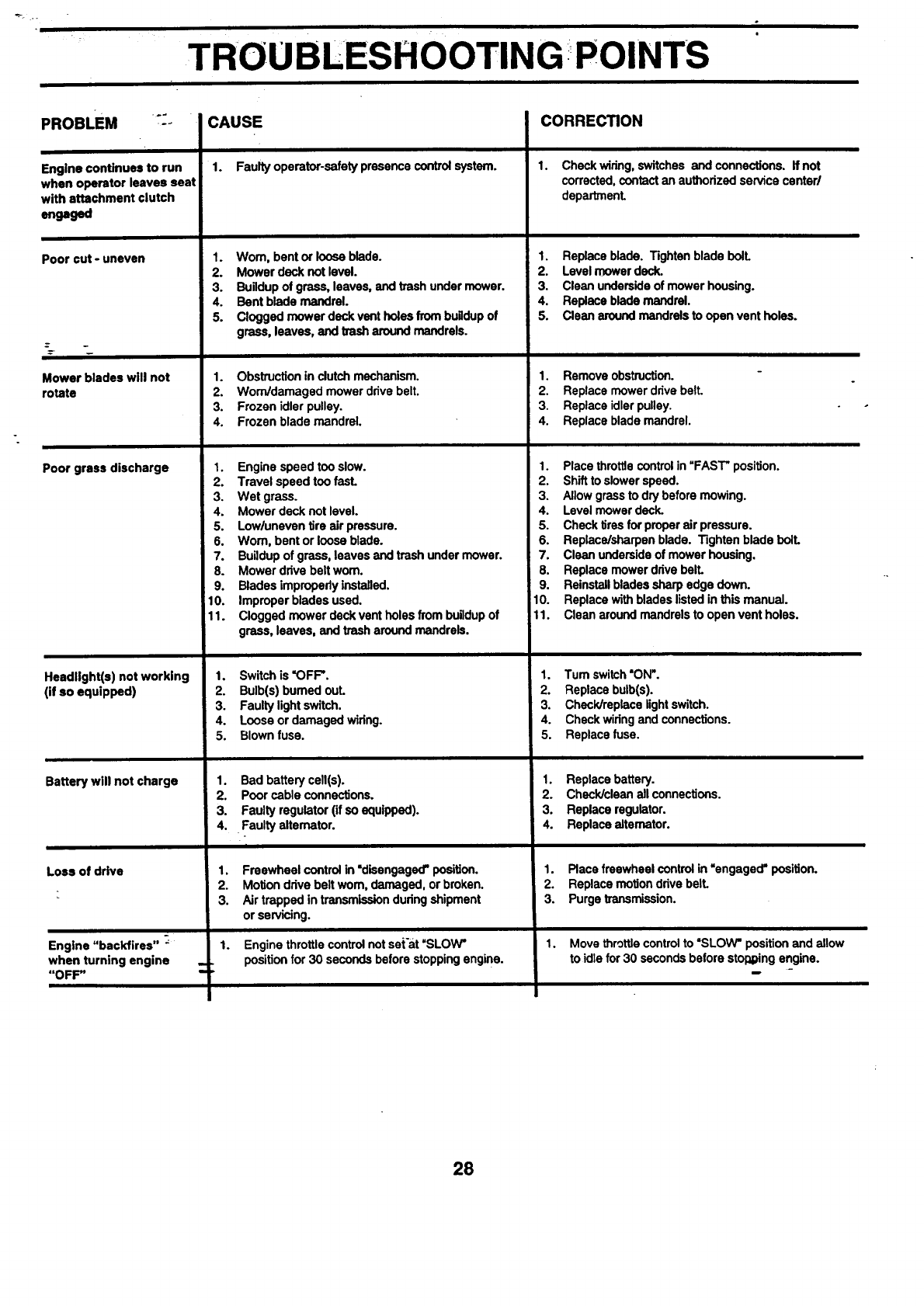
r : TROU BLESH OOTIN G POINTS
PROBLEM ::_
Engine continues to run
when operator leaves seat
with attachment clutch
engaged
Poor cut-uneven
Mower blades will not
rotate
Poor grass discharge
Headlight(s) not working
(if so equipped)
Battery will not charge
Loss of dr_e
Engine "backfires" _
when turning engine
"OFF"
CAUSE
1. Faulty operator-sefety presence control system.
1. Wom, bent or loose blade.
2. Mower deck not level.
3. Buildup of grass, leaves, and trash under mower.
4. Bent blade mandrel.
5. Clogged mower deck vent holes from buildup of
grass, leaves, and trash around mandrels.
CORRECTION
1. Obstruction in clutch mechanism.
2. Wom/damagad mower drive belt.
3. Frozen idler pulley.
4. Frozen blade mandrel.
1.
2.
3.
4.
5.
6.
7,
8.
9.
10.
11.
1.
2.
3.
4.
5.
1.
2.
3.
4.
1.
2.
3.
1.
Engine speed too slow.
Travel speed too fasL
Wet grass.
Mower deck not level.
Low/uneven Ura air pressure.
Worn, bent or loose blade.
Buildup of grass, leaves and trash under mower.
Mower dave belt worn.
Blades improperly installed.
Improper blades used.
Clogged mower deck vent holes from buildup of
grass, leaves, and trash around mandrels.
1. Check wiring, switches and connections. If not
corrected, contact an authodzad service canted
departmenL
1. Replace blade. Tighten blade bolL
2. Level mower deck.
3. Clean underside of mower housing.
4. Replace blade mandrel.
5. Clean around mandrels to open vent holes.
1. Remove obstruction.
2. Replace mower drive belt.
3. Replace idler pulley.
4. Replace blade mandrel.
1. Placethrottlecontrolin "FAST"position.
2. Shifttoslowerspeed.
3. Allowgrassto drybeforemowing.
4. Levelmowerdeck.
5. Checktires for properair pressure.
6. Replace/sharpenblade. Tighten bladeboll
7. Clean undersideof mowerhousing.
8. Replacemower davebell
9. Reinstallbladessharpedge down.
10. Replacewithbladeslistedinthis manual.
11. Cleanaroundmandrelsto openvent holes.
Switch is "OFF'.
Bulb(s) bumed out.
Faulty light switch.
Loose or damaged widng.
Blown fuse.
Bad battery cell(s).
Poor cable connections.
Faulty regulator (if so equipped).
•Faulty alternator.
i
1. Tum switch "ON".
2. Replace bulb(s).
3. Chack/replace light switch.
4. Check widng and connections.
5. Replace fuse.
1. Replace battery.
2. Check/clean all connections.
3. Replace regulator.
4. Replace alternator.
Freewheelcontrolin"disengaged'position.
Motiondrivebeltworn,damaged,orbroken.
Airtrappedin transmissiondudngshipment
or servicing.
Engine throttle control not set'at =SLOW"
position for 30 seconds before stopping engine.
1. Place freewheel control in "engaged" position.
2. Replace motion drive bell
3. Purge transmission.
1. Move throttle control to "SLOW" position and allow
to idle for 30 seconds before stol_ging engine.
28
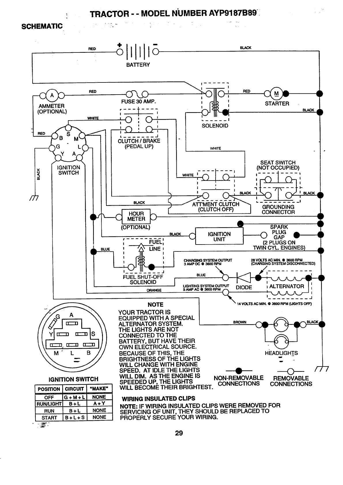
TRACTOR - - MODEL NUMBER AYP9187B89°:
SCHEMATIC .... 11 _, " *
RED
BATrERY
BLACK
)
GLq
IGNITION
SWITCH
RED
WHn_
IGNITION SWITCH
'©:O'
I I
II
FUSE 30 AMP.
, t ,
CLUTCH/BRAKE
(PEDAL UP)
BLACK
HOUR _)
METER
SOLENOID
WHITE
PosmoN CIRCUIT "MAKE"
OFF G+ M+ L NONE
RUN/LIGHT B+ L A+ Y
RUN B+ L NONE
START B+ L + S NONE
(OPTIONAL)
RED
WHITE |_-_l.... I- _1
II
' I
II
I I BLACK
l(CLUTCHOFF) I
STARTER
BLACK
I j
FUEL SHUT-OFF
SOLENOID
ORANGE
NOTE
d IGNITIONUNIT
SEAT SWITCH
(NOT OCCUPIED)
GROUNDING
CONNECTOR
d
SPARK •
_PLUG _
GAP
PLUGS ON
i)
qF
F
I
TWIN CYL. ENGINES) .•
•F
CHARGING SYSTEM OUTPUT 28 VOLTS AC MIN. • 3600 RPM
3 AMP DC Q3600 RPM (CHARGING SYSTEM DISCONNECTED)
BLUE
[ SAMPACO3SOo_IODE ;ALTERNATOR I',
UGHTING SYSTEM OUTPUT I
_'14 VOLTS AC MIN, 0 3600 RPM (LIGHTS OFF)
YOUR TRACTOR IS
EQUIPPED WITH A SPECIAL
ALTERNATOR SYSTEM.
THE LIGHTS ARE NOT
CONNECTED TO THE
BATTERY, BUT HAVE THEIR
OWN ELECTRICAL SOURCE.
BECAUSE OF THIS, THE
BRIGHTNESS OF THE LIGHTS
WILL CHANGE WITH ENGINE
SPEED. AT IDLE THE LIGHTS A
WILL DIM. AS THE ENGINE IS NON-REMOVABLE
SPEEDED UP, THE LIGHTS CONNECTIONS
WILL BECOME THEIR BRIGHTEST.
HEADLIGHTS
m
---O--
REMOVABLE
CONNECTIONS
BROWN
WIRING INSULATED CLIPS
NOTE: IF WIRING INSULATED CLIPS WERE REMOVED FOR
SERVICING OF UNIT, THEY SHOULD BE REPLACED TO
PROPERLY SECURE YOUR WIRING.
29
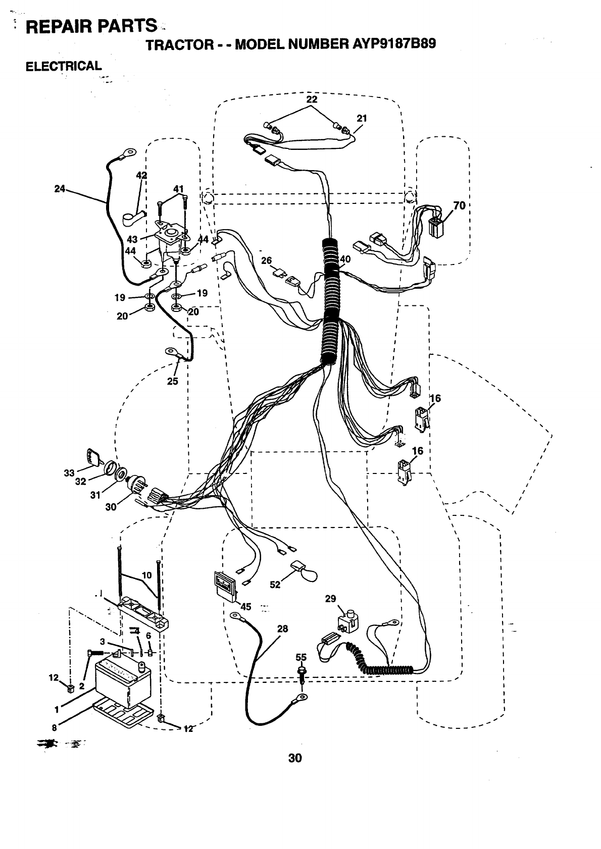
_-. ,_ REPAIR PARTS
TRACTOR - - MODEL NUMBER AYP9187B89
ELECTRICAL
\
21
/
I\
I 1
1
I
I
41 " i
ii I!
\1
19
2O
25
|
I
I
I II
r--
_j_\|
I\'4
I
!
|
|
|
t
|
|
26
I
!
I
29
%
\
I
I
30
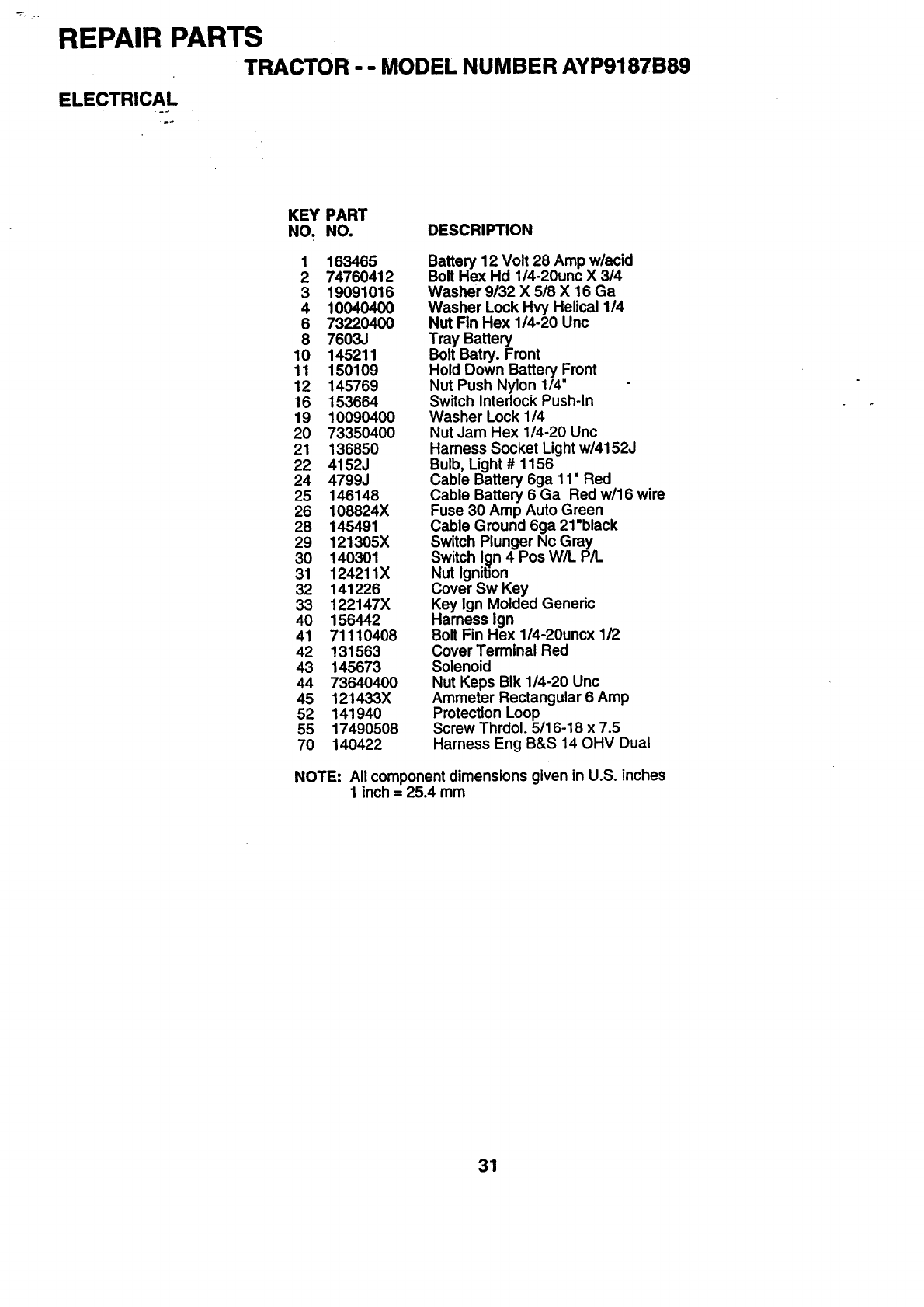
REPAIR. PARTS
TRACTOR - - MODEL NUMBER AYP9187B89
ELECTRICAL
KEY PART
NO. NO. DESCRIPTION
1 163465
2 74760412
3 19091016
4 10040400
6 73220400
8 7603J
10 145211
11 150109
12 145769
16 153664
19 10090400
20 73350400
21 136850
22 4152J
24 4799J
25 146148
26 108824X
28 145491
29 121305X
30 140301
31 124211X
32 141226
33 122147X
40 156442
41 71110408
42 131563
43 145673
44 73640400
45 121433X
52 141940
55 17490508
70 140422
Battery 12 Volt 28 Amp w/acid
Bolt Hex Hd 1/4-20unc X 3/4
Washer 9/32 X 5/8 X 16 Ga
Washer Lock Hvy Helical 1/4
Nut Fin Hex 1/4-20 Unc
Tray Battery
Bolt Batry. Front
Hold Down Battery Front
Nut Push Nylon 1/4"
Switch Interlock Push-In
Washer Lock 1/4
Nut Jam Hex 1/4-20 Unc
Harness Socket Lightw/4152J
Bulb, Light #1156
Cable Battery 6ga 11" Red
Cable Battery 6 Ga Red w/16 wire
Fuse 30 Amp Auto Green
Cable Ground 6ga 21"black
Switch Plunger Nc Gray
Switch Ign 4 Pos W/L P/I.
Nut Ignition
Cover Sw Key
Key Ign Molded Generic
Harness Ign
Bolt Fin Hex 1/4-20uncx 1/2
Cover Terminal Red
Solenoid
Nut Keps BIk 1/4-20 Unc
Ammeter Rectangular 6 Amp
Protection Loop
Screw Thrdol. 5/16-18 x 7.5
Harness Eng B&S 14 OHV Dual
NOTE: All component dimensions given in UoS. inches
1 inch = 25.4 mm
31
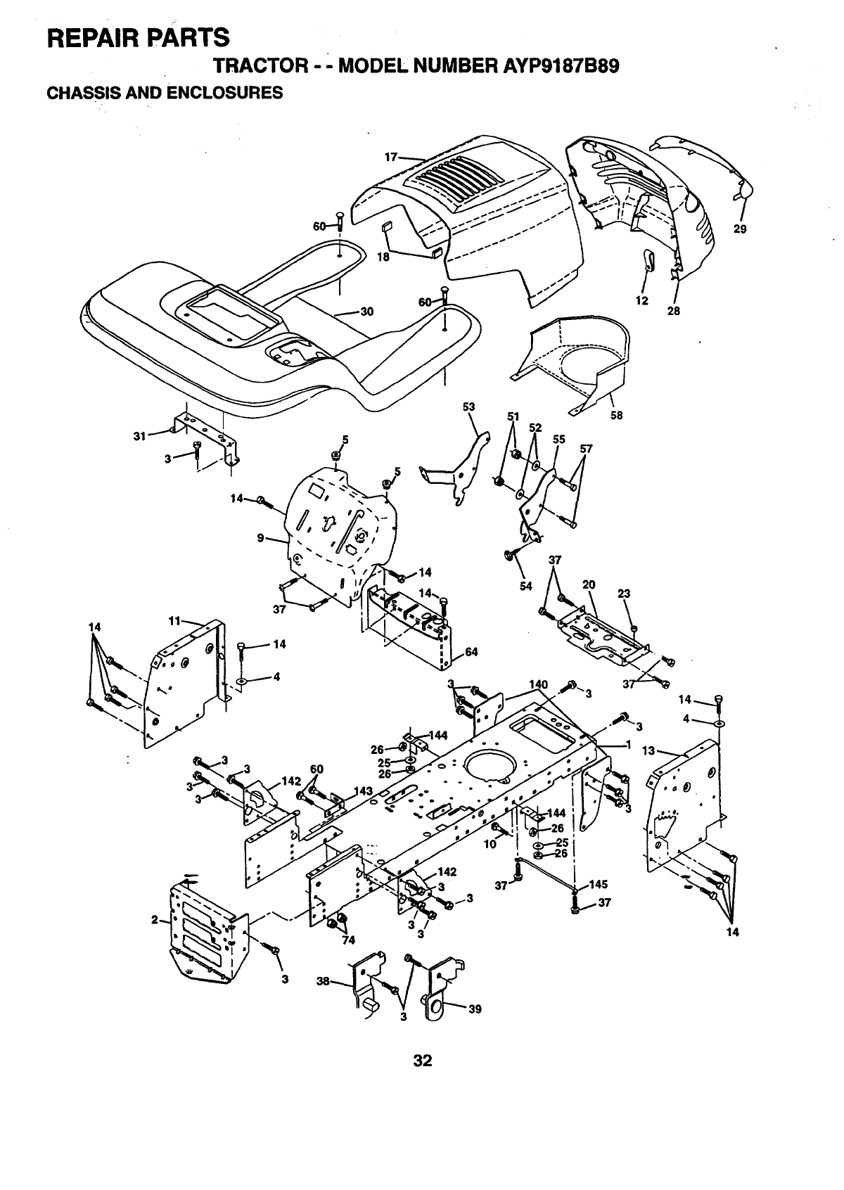
REPAIR PARTS
TRACTOR --MODEL NUMBER AYP9187B89
CHASSIS AND ENCLOSURES
31
14
37
14
53
52 55 57
12
37
54 20 23
28
29
60
y_3
3/
74 3
38_ 39
37
14
32

REPAIR PARTS.
TRACTOR --MODEL NUMBER AYP9187B89
CHASSIS AND ENCLOSURES
KEY PART
NO. NO. DESCRIPTION
1 160392
2 140356
3 17490612
4 19131216
5 155272
9 161917X012
10 72140608
11 155927
12 145660
13 155936
14 17490608
17 159639X418
18 126938X
20 156437
23 124028X
25 19131312
26 73800600
28 157428
29 146654
30 151287X418
31 139976
37 17490508
38 139886
39 139887
51 73800400
52 19091416
53 144697
54 161464
55 144696
57 74780412
58 162266
60 72140606
64 154798
74 73680600
140 158418
142 156095
143 154966
144 154207
145 156524
Chassis Assembly
Drawbar
Screw Thdrol. 3/8-16 x 3/4 Ty-Tt
Washer 13/32 x 3/4 x 16 Ga.
Bumper Hood/Dash
Dash
Bolt Carriage 3/8-16 x 3/4
Panel Asm. Dash Lh Private label
Clip Tinnerman Grile P/L
Panel Dash Rh Lt Private label
Screw Thdrol. 3/8-16 x 112Ty-Tt
Hood Pnt Steel Private Label
Bumper Hood
Plate Mtg Battery/Fuel Tank
Bushing Snap Nyl. BIk Fuel Line
Washer 13/32 x 13116x 12 Ga.
Nut Lock Hex w/Insert 3/8-16 UNC
Grill Private Lable Euro
Lens Grille Private label Euro
Fender/Footrest
Bracket Fender Support
Screw Thdrol. 5/16-18 x 112Tyt
Bracket Asm. Pvt. Lh Mwr. Rear
Bracket Asm. Pvt. Rh Mwr. Rear
Nut Lock Hex W/Ins. 1/4-20
Washer 9/32 x 718 x 16 Ga.
Lh Grille Bracket
Screw Hex 8-18 x 7/8
Bracket, Grill Rh
Bolt Fin Hex 1/4-20 x .75
Air Duct Intake B&S Intek Twin
Bolt, Rdhd Sqnk 3/8-16 UNC x 314
Dash Lower STLT
Nut Crownlock 3/8-16 unc
Bracket Suspension Front
Plate Reinforcement STLT
Bracket Swaybar Chassis
Bracket Pnt Footrest STLT
Rod PivotChassis/Hood
NOTE: All component dimensions given in U.S. inches
1 inch = 25.4 mm
33
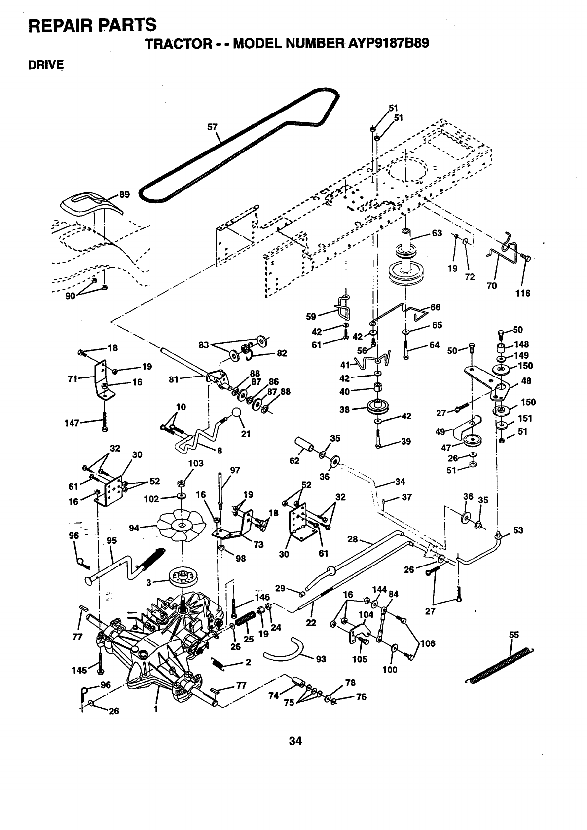
REPAIR PARTS
TRACTOR "- MODEL NUMBER AYP9187B89
DRIVE
32 30
16
95
77
59
/_ 97 36
.__ 30 61
26
22
24
105
16
100
27
O6
34

REPAIR PARTS
TRACTOR - - MODEL NUMBER AYP9187B89
DRIVE
KEY PART KEY PART
NO. NO. DESCRIPTION NO. NO. DESCRIPTION
1 150071 Transaxle (See Breakdown) 64 71170764
Hydro Gear Model 319-0650 65 10040700
2 142431 Spring, Retum, Brake 66 154778
3 143995 Pulley, Transaxle 70 134683
8 154792 Rod Shift Hydro LT 71 140158
10 76020416 Pin Cotter 1/8 x I CAD 72 19132012
16 73800500 Nut Lock Hex W/Ins 5/16-18 Unc P 73 156347
18-_ 74780616 Bolt Fin Hex 3/8-16 Unc x I Gr. 5 74 121199X
19 73800600 Nut Lock Hex W/Wsh 3/8-16 Unc 75 121749X
21 106933X Knob, Round 1/2-13 76 12000001
22 145627 Rod, Brake Hydro 77 123583×
24 73350600 Nut 7R. 121748X
25 106888X Spring, Brake Rod 81 156046
26 19131316 Washer 82 123782X
27 76020412 Pin Cotter 1/8 x3/4 CAD. 83 19171216
28 145204 Rod, Parking Brake 84 161901
29 124236X Cap, Parking Brake Red 86 157480
30 130807 Bracket, Transaxle 87 19212016
32 74760512 Bolt Hex Hd 5/16-18 Unc x 3/4 88 12000008
34 155071 Shaft, Foot Pedal 89 158388
35 120183X Bearing, Nylon 90 124346X
36 19211616 Washer 93 142564
37 1572H Pin, Roll 94 140462
38 123674X Pulley, Idler, Flat 95 144643
39 74760644 Bolt 96 4497H
40 4470J Spacer, Split 97 140469
41 154777 Keeper, Belt Idler 98 73510600
42 19131312 Washer 13/32 x13/16 x12 Gauge 100 19111216
47 127783 Pulley, Idler, V-Groove 102 141322
48 154407 Bellcrank Clutch 103 73940800
49 123205X Retainer, Belt 104 140156
50 74760624 Bolt 105 71070516
51 73680600 Nut Crownlock 3/8-16 UNC 106 74780520
52 73680500 Nut Crownlock 5/16-18 UNC 116 72110610
53 105710X Link, Clutch 144 19111016
55 105709X Spring, Return, Clutch 145 74490540
56 74760620 Bolt Fin Hex 3/8-16 UNC x 1-1/4 146 74490536
57 140294 V-Belt, Ground Drive 147 74490524
59 149312 Keeper, Center Span 148 159103
61 17490612 ScrewThdrol. 3/8-16x3/4Ty.TT 149 122052X
62 8883R Cover, Pedal 150 150935
63 140186 Pulley, Engine 151 19133210
Bolt, Hex
Washer
Keeper Belt Engine
Keeper Belt Engine
Strap Torque Lh Hydro
Washer 13/32 x 1-1/4 x 12 Gauge
Strap Torque Rh Hydro
Spacer, Split
Washer 25/32 x 1-1/4 x 16 Gauge
E-Ring
Key, Square
Washer 25/32 x 1-5/8 x 16 Gauge.
Shaft Asm. Cross Hydro
Spring Torsion T/A
Washer 17/32 x 3/4 x 16 Ga.
Rod, Tie
Bushing
Washer 21/32 x 1-1/4 x 16 Ga.
Ring Klip #5304-62
Console, Hydro
Nut Self Thd Wshd 114
Line Fuel Hydro 4"
Fan, Hydro 7"
Contro/Asm Bypass Hydro
Retainer Spring 1" Zinc/Cad
Keeper Belt Rh Hydro 0750. 18/20"
Nut Keps Hex 3/8-16 Unc
Washer 11/32 x 3/4 x 16 Ga.
Washer Beliville .501D x 1.50D
Nut, Hex, Jam Toplock 1/2-20 UNF
Arm, Control Hydro
Screw Cap Hex 5116 x 18 x 1
Bolt Fin Hex 5/16-18 Unc x 1-114
Bolt Rdhd Sq Neck 3/8-16 x 1.25
Washer
Bolt Hex Flghd 5/16-18 x Gr. 5
Bolt Hex Flghd
Bolt Hex Flghd
Spacer
Spacer Retainer
Bushing Nylon Collered
Nut Self Thd Wshd
NOTE: All component dimensions given in U.S. inches
1 inch = 25.4 mm
35

REPAIR PARTS
TRACTOR -- MODEL NUMBER AYP9187B89
STEERING ASSEMBLY
€- -_p
o39
• • • ,=
-. - -_-.-_?-.-;..
)-'I
' -,''''--42
i•
I ;Y"""_a7
I
62 44
4O
\
\
25
36

REPAIR PARTS
TRACTOR- -MODEL NUMBER AYP9187B89
STEERING ASSEMBLY
KEY PART
NO. NO. DESCRIPTION
1 140044
2 137094
3 157479
4 157478
5 6266H
6 121748X
7 19272016
8 12000029
10 154432
11 10040600
13 154779
15 73901000
17 156546
18 57079
19 124035X
20 126684X
22 71200410
23 127501
25 154406
27 136874
29 17490612
32 137347
36 155099
37 152927
38 140045
39 19133808
40 781 OH
41 100711L
42 145054
43 121749X
44 153720
46 121232X
47 6855M
51 73800500
54 74780520
62 156594
63 74780616
65 154780
66 154404
67 74781044
68 154429
74 109850
75 109851
76 137156
77 73700600
78 73360600 ....
Wheel Steering Ayp/keich BIk
Axle Front Cast
Spindle Asm LH
Spindle Asm RH
Bearing Race Thrust Harden
Washer 25/32 X 1-5/8 X 16 Ga
Washer 27/32 X 1-1/4 X 16 Ga
Ring Klip #t5304-75
Link Drag Extended Cast
Washer. Lock Hvy Hlcl Spr 3/8
Spacer.Bearing Axle Front
Nut Lock Flange 5/8-11 Unc
Shaft Asm Strg
Washer Thrust 515x 750x 033
Support Shaft
Washer Shim 114X 5/8 X 062
Screw Hex Socket 1/4-20 x 518
Shaft Asm Pittman
Bracket Steering
Gear Sector 22 Teeth
Screw Thdrol 3/8-16x3/4 Ty-tt
Rod Asm Tie Ball Jt Adj
BushingSteering
Screw
Cap Wheel Steer Ayp
Washer 13/32 x 2-3/8 x 8 Ga
Nut Lock Center 3/8-24 Unf
Adapter Wheel Strg .640/.635
Boot Shaft Steering
Washer 25/32 X 1 1/4 X 16 Ga
Shaft Extension Steering Non Adjust.
Cap Spindle Fr Top BIk
Fitting Grease
Nut Lock Hex W/Ins. 5/16-18 Unc P
Bolt Fin Hex 5/16-18 Uric P
Kit, Steering Assembly
Bolt Fin Hex 3/8-16unc x 1
Spacer Axle
Bearing Arm Pittman
Bolt Fin Hex 5/8-11 Unc x 2-3/4
Brace Axle
Joint Asm Ball Rh
Joint Asm Ball Lh
Rod Tie Ball J Adj
Nut Hex Jam 3/8-24 Unf Lh
Nut Hex Jam 3/8-24 Unf
NOTE: All component dimensions given in U.S. inches
1 inch = 25.4 mm
37
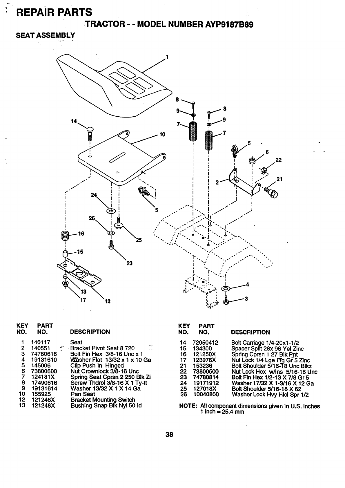
REPAIR PARTS
TRACTOR - -MODEL NUMBER AYP9187B89
SEAT ASSEMBLY
+.._
14
26
23
I
i
I
i
I
!
J
i
I
i
I
i
I
KEY PART
NO. NO.
1 140117
2 140551 _
3 74760616
4 19131610
5 145006
6 73800600
7 124181X
8 17490616
9 19131614
10 155925
12 121246X
13 121248X
DESCRIPTION
Seat
Bracket Pivot Seat 8 720 ':
Bolt Fin Hex 3/8-16 Unc x 1
V_sher Flat 13/32 x 1 x 10 Ga
Clip Push In Hinged
Nut Crownlock 3/8-16 Unc
Spring Seat Cprsn 2 250 BIk Zi
Screw Thdrol 3/8-16 X 1 Ty-tt
Washer 13/32 X 1 X 14 Ga
Pan Seat
Bracket Mounting Switch
Bushing Snap BIk Nyl 50 Id
KEY PART
NO. NO. DESCRIPTION
14 72050412
15 134300
16 121250X
17 123976X
21 153236
22 73800500
23 74780814
24 19171912
25 127018X
26 10040800
Bolt Carriage 1/4-20x1-1/2
Spacer Split 28x 96 Yel Zinc
Spring Cprsn 1 27 BIk Pnt
Nut Lock 1/4 Lge F"r_qGr-5 Zinc
Bolt Shoulder 5116-18 Unc Blkz
Nut Lock Hex w/Ins 5/16-18 Unc
Bolt Fin Hex 1/2-13 X718 Gr 5
Washer 17/32 X 1-3/16 X 12 Ga
Bolt Shoulder 5/16-18 X 62
Washer Lock Hvy Hlcl Spr 1/2
NOTE: All component dimensions given in U.S. inches
1 inch =25.4 mm
38

REPAIR PARTS
TRACTOR - - MODEL NUMBER AYP9187B89
DECALS
:...d
9-13 2 3 18 12 12 18 4 10
11 20
8
5
14
7
15
13
KEY
NO. PART
NO.
1 156811
2 143470
3 141579
4 141580
5 273727
6 141583
7 162700
8 141517
9 127520
6
DESCRIPTION
Decal, Oper. Instr. Fend STLTH
Decal, Insert Strg Wizard Plus
Decal, Hood, R.H.
Decal, Hood, L.H.
Decal, HP Engine
Decal, Deck Mulching Wizard Plus
Decal, Fender Auto Rad Wiz
Decal, Mower Vented Wizard Plus
Decal, USA White
WHEELS AND TIRES
4,10
11
KEY PART
NO. NO.
10 157002
11 150218
12 162550
13 143349
14 160396
15 142341
18 143388
20 145005
-- 138311
-- 154515
-- 154516
- - 165113
DESCRIPTION
Decal, Fender Danger
Decal, Lens Logo
Decal, Pnl Sd B&S Intek 18 Wiz
Decal, Wiz Hyd 42"
Decal, V-Belt Schematic
Decal, Drawbar Control Mvt Hyd
Name plate Hood Wizard Large
Decal, Battery Dngr/Psn PI Sym
Decal, Lift Handle
Pad Footrest LH STLT
Pad Footrest RH STLT
Owner's Manual
KEY PART
NO. NO. DESCRIPTION
1 59192
2 65139
3106222X
459904
5 106732X427
6 278H
79040H
8 106108X427
9 122082X
10 7152J
11 104757X
-- 144334
Cap Valve Tire
Stem Valve
Tire F Ts 15 X6 0 -6 Service
Tube Front (Service Item Only)
Rim Asm 6" front White Service
Fitting Grease/_Front Wheel Only)
Bearing Flange.(.Front Wheel Only)
Rim Asm 8" rear White Service
Tire R Ts 20 X 10-8 C Service
Tube Rear (Service Item Only)
Cap Axle BIk I 50 X 1 00
Sealant, Tire (10 oz. Tube)
NOTE: All component dimensions given in U.S. inches
1 inch = 25.4 mm
39
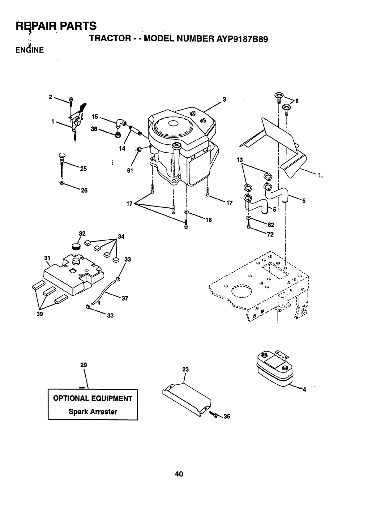
RqPAI R PARTS
,_. TRACTOR - - MODEL NUMBER AYP9187B89
EN(_INE
39
2
1_ 15
14
31
81
29
OPTIONAL EQUIPMENT
Spark Arrester
23
/
I
I
40

REPAIR PARTS
TRACTOR - -MODEL NUMBER AYP9187B89
ERGINE
KEY PART
NO. NO. DESCRIPTION
1 148875
2 17720410
4 149723
5 160589
6159955
8 150176
10 162797
13 273485
14 132803,3,,
15 13200300
16 11050600
17 17490624
23 159880
25 145996
26 73920600
29 137180
31 157103
32 140527
33 123487X
34 106082X
35 17490512
37 8543R
38 ......
39 109227X
62 10040500
72 71070512
61 128861
Control Throt 36 LH Flag
Screw Hex Thd Cut 1/4-20x5/8'T
Engine, Briggs Model No. 407777
Muffler Asm Twin Lo-Tone •
Exhaust Asm RH B&S 20 HP Vert Intek
Exhaust Asm LH B&S 20 HP Vert Intek
Bolt 5/16-18 UNC x 314w/Sems
Shield Heat
Gasket Muffler
Nipple Pipe 4-i/2"
Elbow Std 90 Degree 3/8-18 Npt
Washer Lock Ext Tooth 3/8
Screw Thdrol 3/8-16 X 1-1/2 Tt
Shield Browning
Control Choke
Nut Keps 3/8-24 Unf
Kit Spark Arrestor
Tank Fuel
Cap Asm Fuel
Clamp Hose BIk
Pad Spacer
Screw Thdrol 5/16-18 x 3/4
Line Fuel 54"
Plug Oil Drain (Order From Engine
Manufacturer)
Pad Idler
Washer Lock Hvy Helical 5/16
Screw Hex Hd Cap
Nut Flange 1/4-20 Starter Nut
NOTE: All component dimensions given inU. S. inches
1 inch = 25.4 mm
41
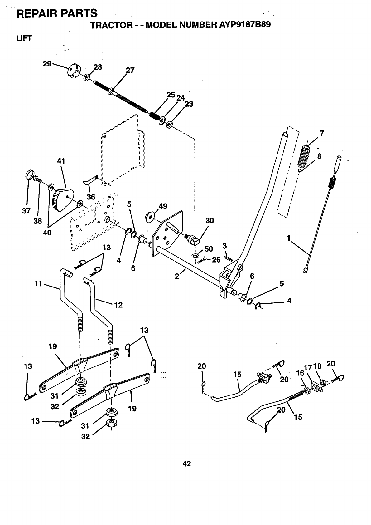
'REPAIR PARTS .,i
TRACTOR --MODEL NUMBER AYP9187B89
LIFT
37
38
11
4O
\
4 6
49
2
3O
3
26
6
7
/
/
°°
,/
1
5
12 4
19
13 i
I
i
31 _19
32
13
o.r
2O
15 20
15
718 20
42

REPAIR PARTS
TRACTOR --MODEL NUMBER AYP9187B89
LIFT
KEY PART
NO. NO. DESCRIPTION
1 159460
2 159471
3 105767X
4 12000002
5 19211621
6 120183X
7 125631X
8 122365X
11 139865
12 139866
13 4939M
15 127218
16 73350800
17 130171
18 73680800
19 139868
20 163552
23 110807X
24 19131016
25 2876H
26 76020308
27 126971X
28 73350600
29 138057
30 150233
31 140302
32 73540600
36 155097
37 123935X
38 17490512
40 19112410
41 155096
49 145212
50 110452X
Wire Asm Inner W/Plunger
Shaft Asm Lft RH
Pin Groove
E-dng Truarc #5133-62
Washer Pltd 21/32 X 1 X 21 Ga
Bearing Nylon
Grip Handle Fluted
Button Plunger Red
Link Lift LH
Link Lift RH
Retainer Soring
Link Front
Nut Jam Hex 1/2-13 Unc
Trunnion BIk Zinc
Nut Crownlock 1/2-13 Unc
Arm Suspension Rear
Retainer Spring
Nut Special
Washer 13/32 X 5/8 X 16 Ga
Spring 2-1/8"
Pin Cotter 3/32 X 1/2
Rod Adj LiftZinc 7.49 Wrk Lg
Nut Hex Jam 3/8-16 Unc
Knob Inf 3/8-16 Unc BIkW/sym
Trunnion Dp Stop Dbl Thds PLT
Bearing Pvt. Lift Spherical
Nut Crownlock 3/8-24
Pointer Height Indicator
Plug Hole BIk 1.485 /1.515 Dia.
Screw Thdrol 5/16-18 x 3/4
Washer 11/32 x 1-1/2 x 10 Ga.
Indicator Height STLT
Nut Hex Flange Lock
Nut Push Phos & Oil
NOTE: All component dimensions given in U.S. inches
1 inch = 25.4 mm
43
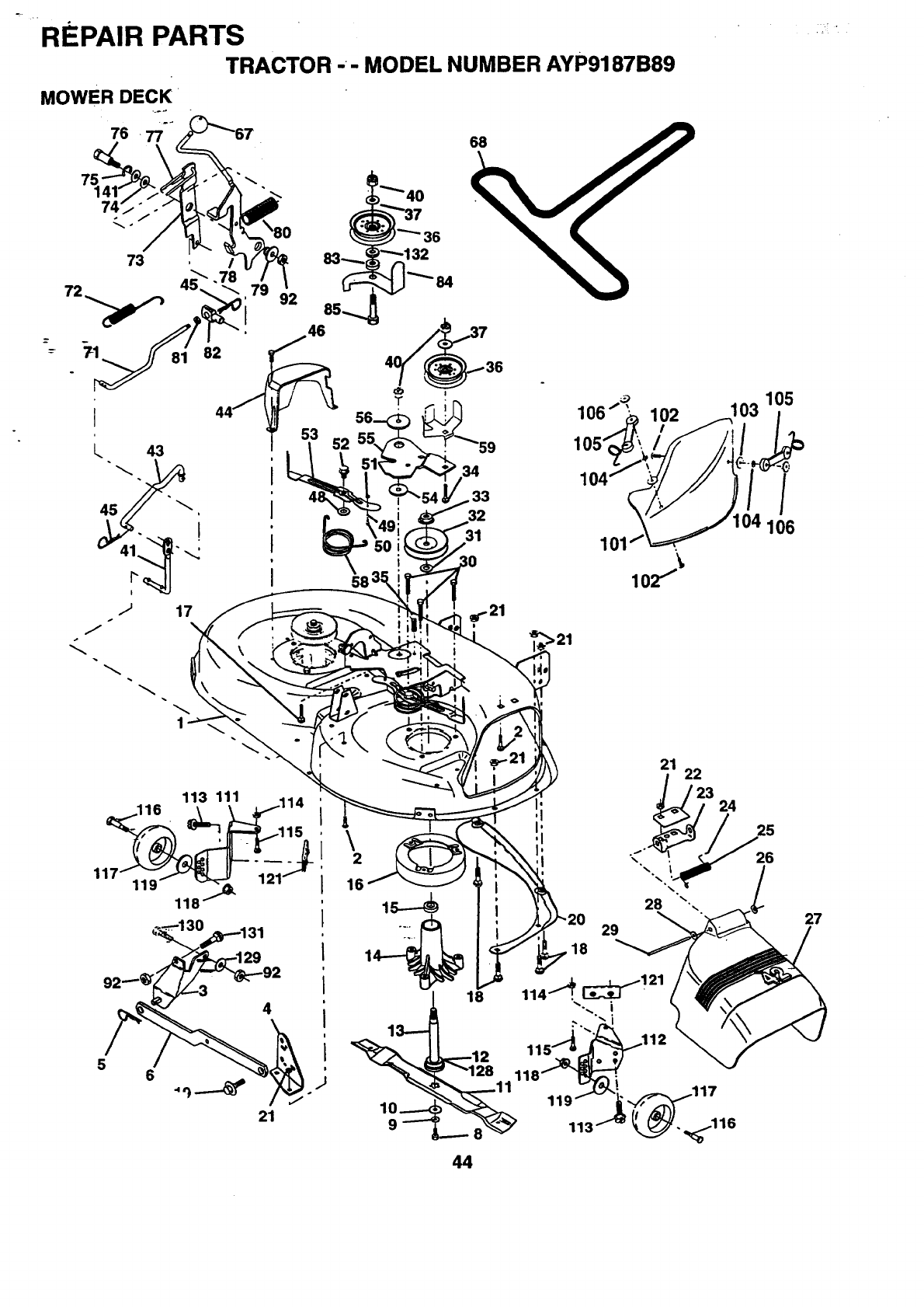
REPAIR PARTS
TRACTOR -- MODEL NUMBER AYP9187B89
MOWER DECK
I
I
I
I
34
,33
32
31
119
113 111
118
!\2
16
56
21
101
102 103 105
/
106
29
18
21 22
_[_23 24
28 27
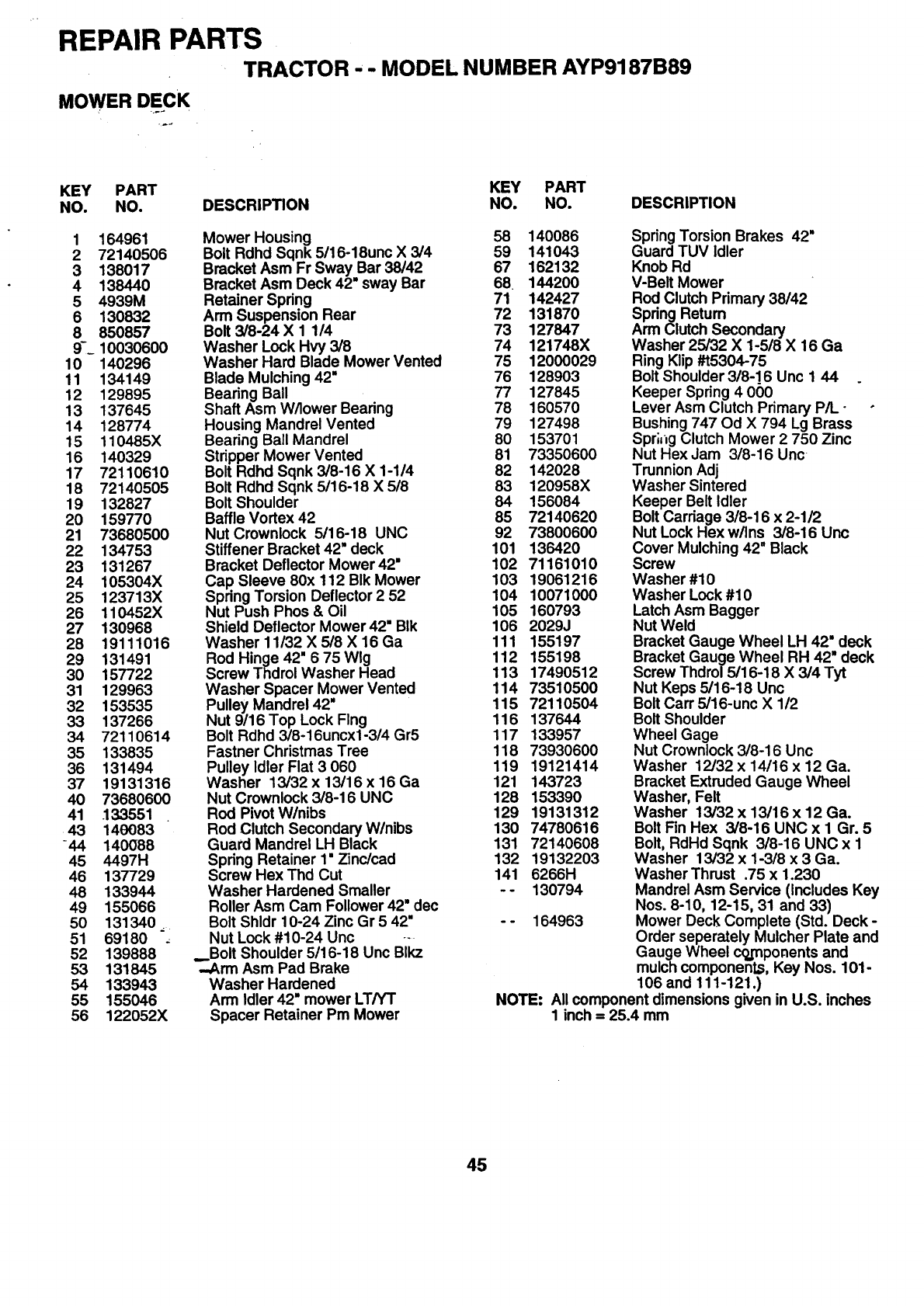
REPAIR PARTS
TRACTOR - - MODEL NUMBER AYP9187B89
MOWER DECK
KEY PART KEY PART
NO. NO. DESCRIPTION NO. NO. DESCRIPTION
1 164961 Mower Housing 58 140086
2 72140506 Bolt Rdhd Sqnk 5/16-18unc X 3/4 59 141043
3 138017 Bracket Asm Fr Sway Bar 38/42 67 162132
4 138440 Bracket Asm Deck 42" sway Bar 68 144200
5 4939M Retainer Spring 71 142427
6 130832 Arm Suspension Rear 72 131870
8 850857 Bolt 3/8-24 X 1 114 73 127847
9-_ 10030600 Washer Lock Hvy 3/8 74 121748X
10 140296 Washer Hard Blade Mower Vented 75 12000029
11 134149 Blade Mulching 42" 76 128903
12 129895 Bearing Ball 77 127845
13 137645 Shaft Asm W/lower Bearing 78 160570
14 128774 Housing Mandrel Vented 79 127498
15 110485X Bearing Ball Mandrel 80 153701
16 140329 Stripper Mower Vented 81 73350600
17 72110610 Bolt Rdhd Sqnk 3/8-16 X 1-1/4 82 142028
18 72140505 Bolt Rdhd Sqnk 5/16-18 X 5/8 83 120958X
19 132827 Bolt Shoulder 84 156084
20 159770 Baffle Vortex 42 85 72140620
21 73680500 Nut Crownlock 5/16-18 UNC 92 73800600
22 134753 Stiffener Bracket 42" deck 101 136420
23 131267 Bracket Deflector Mower42" 102 71161010
24 105304X Cap Sleeve 80x 112 BIk Mower 103 19061216
25 123713X Spring Torsion Deflector 2 52 104 10071000
26 110452X Nut Push Phos & Oil 105 160793
27 130968 Shield Deflector Mower 42" BIk 106 2029J
28 19111016 Washer11/32 X 5/8 X16 Ga 111 155197
29 131491 Rod Hinge 42" 6 75 Wig 112 155198
30 157722 Screw Thdrol Washer Head 113 17490512
31 129963 Washer Spacer Mower Vented 114 73510500
32 153535 Pulley Mandrel42" 115 72110504
33 137266 Nut 9/16 Top Lock Flng 116 137644
34 72110614 Bolt Rdhd 3/8-16uncx1-3/4Gr5 117 133957
35 133835 Fastner Christmas Tree 118 73930600
36 131494 Pulleyldler Flat 3 060 119 19121414
37 19131316 Washer 13/32x 13/16x 16 Ga 121 143723
40 73680600 Nut Crownlock 3/8-16 UNC 128 153390
41 133551 Rod PivotW/nibs 129 19131312
43 149083 Rod Clutch Secondary W/nibs 130 74780616
-44 140088 Guard Mandrel LH Black 131 72140608
45 4497H Spring Retainer 1" Zinc/cad 132 19132203
46 137729 Screw Hex Thd Cut 141 6266H
48 133944 Washer Hardened Smaller - - 130794
49 155066 Roller Asm Cam Follower 42" dec
50 131340 _Bolt Shldr 10-24 Zinc Gr 5 42" - - 164963
51 69180 ,Nut Lock #10-24 Unc ---
52 139888 _Bolt Shoulder 5/16-18 Unc Blkz
53 131845 ,..Arm Asm Pad Brake
54 133943 Washer Hardened
55 155046 Arm Idler 42" mower LT/YT
56 122052X Spacer Retainer Pm Mower
Spring Torsion Brakes 42"
Guard TUV Idler
Knob Rd
V-Belt Mower
Rod Clutch Primary 38/42
Spring Return
Arm Clutch Secondary
Washer 25/32 X 1-5/8 X 16 Ga
Ring Klip#15304-75
Bolt Shoulder 3/8-16 Unc 1 44
Keeper Spring 4 060
Lever Asm Clutch Primary P/L-
Bushing 747 Od X 794 Lg Brass
Spr;l_gClutch Mower 2 750 Zinc
Nut Hex Jam 3/8-16 Unc
Trunnion Adj
Washer Sintered
Keeper Belt Idler
Bolt Carriage 3/8-16 x 2-1/2
Nut Lock Hex w/Ins 3/8-16 Unc
Cover Mulching 42" Black
Screw
Washer #10
Washer Lock #10
Latch Asm Bagger
Nut Weld
Bracket Gauge Wheel LH 42" deck
Bracket Gauge Wheel RH 42" deck
Screw Thdrol 5/16,18 X 3/4 Tyt
Nut Keps 5/16-18 Unc
Bolt Carr 5/16-unc X 1/2
Bolt Shoulder
Wheel Gage
Nut Crownlock 3/8-16 Unc
Washer 12/32 x 14/16 x 12 Ga.
Bracket Extruded Gauge Wheel
Washer, Felt
Washer 13/32 x 13116 x 12 Ga.
Bolt Fin Hex 3/8-16 UNC x I Gr. 5
Bolt, RdHd Sqnk 3/8-16 UNC x 1
Washer 13/32 x 1-3/8 x 3 Ga.
Washer Thrust .75 x 1.230
Mandrel Asm Service (Includes Key
Nos. 8-10, 12-15, 31 and 33)
Mower Deck Complete (Std. Deck -
Order seperately Mulcher Plate and
Gauge Wheel cojnponents and
mulch components, Key Nos. 101-
106 and 111-121.)
NOTE: All component dimensions given in U.S. inches
1 inch =25.4 mm
45
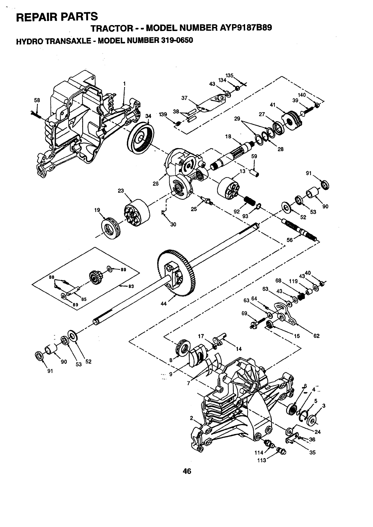
REPAIR PARTS
TRACTOR-" MODEL NUMBER AYP9187B89
HYDRO TRANSAXLE -MODEL NUMBER319-0650
58
91
90 53 52
19
23
26
!
-36
35
46
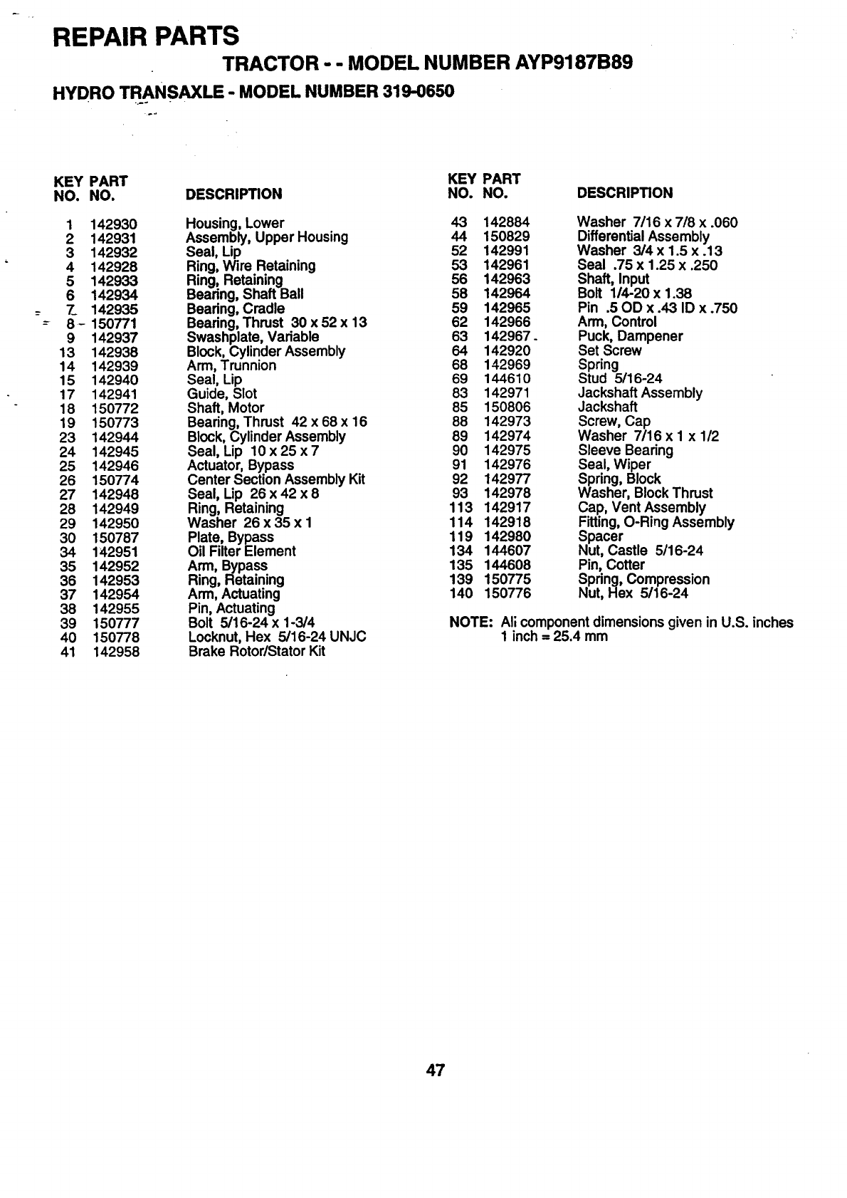
REPAIR PARTS
TRACTOR - -MODEL NUMBER AYP9187B89
HYDRO TRANSAXLE - MODEL NUMBER 319-0650
KEY PART KEY PART
NO. NO. DESCRIPTION NO. NO. DESCRIPTION
1 142930 Housing, Lower 43 142884 Washer 7116 x7/8 x.060
2 142931 Assembly, Upper Housing 44 150829 Differential Assembly
3 142932 Seal, Lip 52 142991 Washer 3/4 x 1.5 x .13
4 142928 Ring, Wire Retaining 53 142961 Seal .75 x 1.25 x .250
5 142933 Ring, Retaining 56 142963 Shaft, Input
6 142934 Bearing, Shaft Ball 58 142964 Bolt 114-20 x 1.38
7_ 142935 Bearing, Cradle 59 142965 Pin .50D x .43 ID x .750
8 - 150771 Bearing, Thrust 30 x 52 x 13 62 142966 Arm, Control
9 142937 Swashplate, Variable 63 142967. Puck, Dampener
13 142938 Block, Cylinder Assembly 64 142920 Set Screw
14 142939 Arm, Trunnion 68 142969 Spring
15 142940 Seal, Lip 69 144610 Stud 5/16-24
17 142941 Guide, Slot 83 142971 Jackshaft Assembly
18 150772 Shaft, Motor 85 150806 Jackshaft
19 150773 Bearing, Thrust 42 x 68 x 16 88 142973 Screw, Cap
23 142944 Block, Cylinder Assembly 89 142974 Washer 7/16 x 1 x 1/2
24 142945 Seal, Lip 10 x 25 x 7 90 142975 Sleeve Bearing
25 142946 Actuator, Bypass 91 142976 Seal, Wiper
26 150774 Center Section Assembly Kit 92 142977 Spring, Block
27 142948 Seal, Lip 26 x 42 x 8 93 142978 Washer, Block Thrust
28 142949 Ring, Retaining 113 142917 Cap, Vent Assembly
29 142950 Washer 26 x 35 x 1 114 142918 Fitting, O-Ring Assembly
30 150787 Plate, Bypass 119 142980 Spacer
34 142951 Oil Filter Element 134 144607 Nut, Castle 5/16-24
35 142952 Arm, Bypass 135 144608 Pin, Cotter
36 142953 Ring, Retaining 139 150775 Spring, Compression
37 142964 Arm, Actuating 140 150776 Nut, Hex 5/16-24
38 142955 Pin, Actuating
39 150777 Bolt 5/16-24 x 1-3/4 NOTE: All component dimensions given in U.S. inches
40 150778 Locknut, Hex 5/16-24 UNJC 1 inch = 25.4 mm
41 142958 Brake Rotor/Stator Kit
47

REPAIR PARTS
'TRACTOR - - MODEL NUMBER AYP9187B89
BRIGGS & S.TRA'I-I'ON ENGINE - MODEL NUMBER 407777, TYPE NUMBER 0119-E1
823T 11_11_ 592 s
'_"REQUIRES SPECIAL TOOLS
TO INSTALL. SEE REPAIR
INSTRUCTION MANUAL
190
12
15Q]I IB!
195
87 E) 20_
26
7-'__ o
27
146
741
46
48

REPAIR PARTS
TRACTOR - - MODEL NUMBER AYP9187B89
BRIGGS &.STRATFON ENGINE -MODEL NUMBER 407777, TYPE NUMBER 0119-E1
5'1
* ReOUmes
TO INSTALL SEE REPAIR
INSTRUCTION MANUAL
\
lo=SI
51
7
1022
_k REQUIRES SPECIAL TOOLS
TO INSTALL SEE REPAIR
INSTRUCTION MANUAL
1022
loe
615A
615 _:_
6340 -- 351
87 O216
211
49

REPAIR PARTS "
TRACTOR --MODEL NUMBER AYP9187B89
BRIGGS & ST.RATrON ENGINE -MODEL NUMBER 407777, TYPE NUMBER 0119-E1
iiii,
119!
881
1411 t95 t102
108_
.:=,
865B
1005
823 823
222 265
351
3O5
163 _'_ _
7s
188
1006
3O5
5O
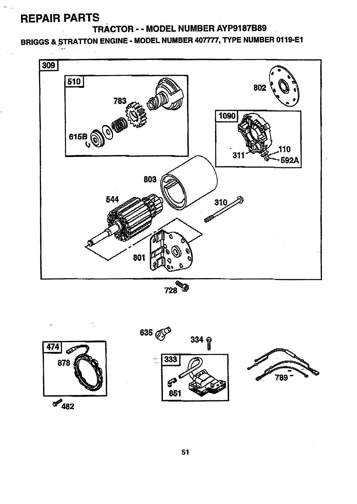
REPAIR PARTS
TRACTOR- -MODEL NUMBER AYP9187B89
BRIGGS &oSTRATTON ENGINE - MODEL NUMBER 407777, TYPE NUMBER 0119-E1
615B
783
i
10901
31
802
592A
8O3
544
i I i i
_482
51

REPAIR PARTS
TRACTOR - - MODEL NUMBER AYP9187B89
BRIGGS & STRATTON ENGINE -MODEL NUMBER 407777, TYPE NUMBER 0119-E1
52_
116D
523
116C
1027
788
%
__ iii
1035 _.
,1,'977 CARBURETOR GASKET SET
355
lo, _ 1soi_ 98T
116_ 116A_ 633 @
-'e121 CAR'BURETOR KIT'
51 _'_ 117_ --
1oo+,o+=!,_o_J_l
116 _:_ 355 _987 (_
116A _633 @
. . 358 GASKET-SET
s_ 20@ " ______
s_ SlAL©_©J sss_.=
i., A-103,3VALVE OVERHAUL KIT .- ' _ -
_J 868 _ I0",_
52
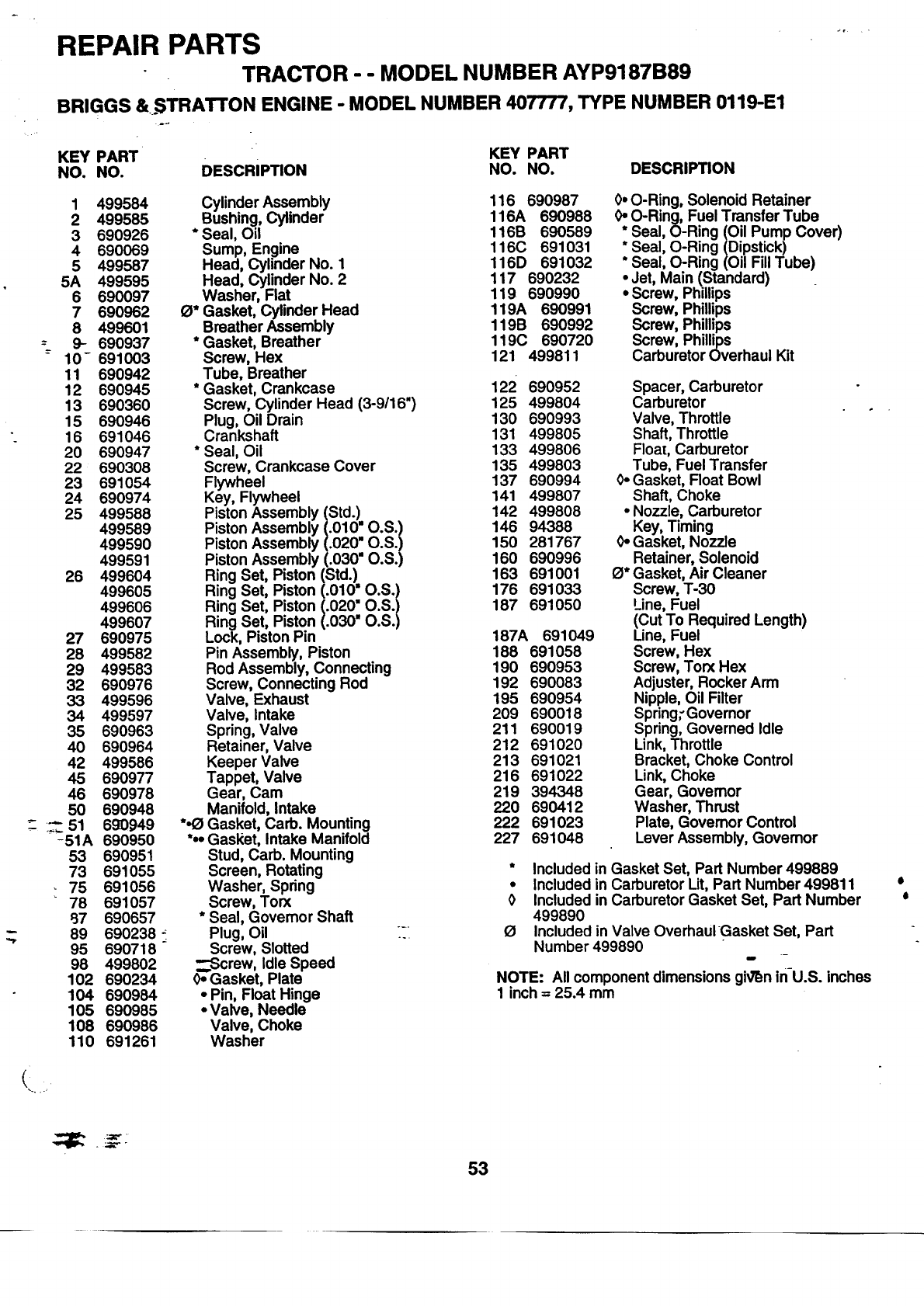
REPAIR PARTS
TRACTOR --MODEL NUMBER AYP9187B89
BRIGGS &.STRATrON ENGINE -MODEL NUMBER 407777, TYPE NUMBER 0119-E1
41 •
KEY PART KEY PART
NO. NO. DESCRIPTION NO. NO. DESCRIPTION
1
2
3
4
5
5A
6
7
8
9-
10-
11
12
13
15
16
20
22
23
24
25
26
27
28
29
32
33
34
35
40
42
45
46
50
51
-51A
53
73
75
78
97
89
95
98
102
104
105
108
110
499584 Cylinder Assembly
499585 Bushing, Cylinder
690926 * Seal, Oil
690069 Sump, Engine
499587 Head, Cylinder No. 1
499595 Head, Cylinder No. 2
690097 Washer, Flat
690962 _* Gasket, Cylinder Head
499601 Breather Assembly
690937 * Gasket, Breather
691003 Screw, Hex
690942 Tube, Breather
690945 * Gasket, Crankcase
690360 Screw, Cylinder Head (3-9/16")
690946 Plug, Oil Drain
691046 Crankshaft
690947 * Seal, Oil
690308 Screw, Crankcase Cover
691054 Flywheel
690974 Key, Flywheel
499588 Piston Assembly (Std.)
499589 Piston Assembly (.010" O.S.)
499590 Piston Assembly (.020" O.S.)
499591 Piston Assembly (.030" O.S.)
499604 Ring Set, Piston (Std.)
499605 Ring Set, Piston (.010* O.S.)
499606 Ring Set, Piston (.020" O.S.
499607 Ring Set, Piston (.030" O.S.
690975 Lock, Piston Pin
499582 Pin Assembly, Piston
499583 Rod Assembly, Connecting
690976 Screw, Connecting Rod
499596 Valve, Exhaust
499597 Valve, Intake
690963 Spring, Valve
690964 Retainer, Valve
499586 Keeper Valve
690977 Tappet, Valve
690978 Gear, Cam
690948 Manifold, Intake
690949 *.O Gasket, Carb. Mounting
690950 *.• Gasl(et, Intake Manifold
690951 Stud, Carb. Mounting
691055 Screen, Rotating
691056 Washer, Spring
691057 Screw, Torx
690657 * Seal, Governor Shaft
690238 _ Plug, Oil _ZI
690718 Screw, Slotted
499802 _---Screw, Idle Speed
690234 0- Gasket, Plate
690984 ° Pin, Float Hinge
690985 • Valve, Needle
690986 Valve, Choke
691261 Washer
116 690987
116A 690988
116B 690589
116C 691031
116D 691032
117 690232
119 690990
119A 690991
119B 690992
119C 690720
121 499811
0. O-Ring, Solenoid Retainer
0. O-Ring, Fuel Transfer Tube
*Seal, O-Ring (Oil Pump Cover)
*Seal, O-Ring (Dipstick)
* Seal, O-Ring (Oil Fill Tube)
Jet, Main (Standard)
• Screw, Phillips
Screw, Phillips
Screw, Phillips
Screw, Phillips
Carburetor Overhaul Kit
122 690952 Spacer, Carburetor
125 499804 Carburetor
130 690993 Valve, Throttle
131 499805 Shaft, Throttle
133 499806 Floa[, Carburetor
135 499803 Tube, Fuel Transfer
137 690994 0.Gasket, Float Bowl
141 499807 Shaft, Choke
142 499808 ° Nozzle, Carburetor
146 94388 Key, Timing
150 281767 0-Gasket, Nozzle
160 690996 Retainer, Solenoid
163 691001 O'Gasket, AirCleaner
176 691033 Screw, T-30
187 691050 Line, Fuel
(Cut To Required Length)
187A 691049 Line, Fuel
188 691058 Screw, He){
190 690953 Screw, Torx Hex
192 690083 Adjuster, Rocker Arm
195 690954 Nipple, Oil Filter
209 690018 Spring.Governor
211 690019 Spring, Governed Idle
212 691020 Link, Throttle
213 691021 Bracket, Choke Control
216 691022 Link, Choke
219 394348 Gear, Governor
220 690412 Washer, Thrust
222 691023 Plate, Governor Control
227 691048 Lever Assembly, Governor
* Included in Gasket Set, Part Number 499889
•Included in Carburetor Lit, Part Number 499811
0 Included in Carburetor Gasket Set, Part Number
499890
OIncluded in Valve Overhaul Gasket Set, Part
Number 499890
i
NOTE: All component dimensions giv'_nin-U.S, inches
1 inch = 25.4 mm
o
o
53

REPAIR PARTS
TRACTOR - - MODEL NUMBER AYP9187B89
BRIGGS & ST.RATTON ENGINE -MODEL NUMBER 407777, TYPE NUMBER 0119-E1
KEY PART KEY PART
NO. NO. DESCRIPTION NO. NO. DESCRIPTION
240 691035 Filter, Fuel 823 690960
252 690956 Element, Breather 847 499602
256 690957 Retainer, Element 851 691234
258 691003 Screw, Hex 855 691011
265 691024 Clamp, Casing 865 691012
277 691029 Nut, Hex 865A 691013
304 691004 Housing, Blower 865B 691015
305 691005 Screw, Hex
309 691262 Motor, Starter 868
310 691263 Screw, Hex 871
311 691264 Brush Set 878
332 690059 Nut, Flywheel 881
333 691060 Armature, Magneto 883
334 691061 Screw, Armature Mounting 918
337 690965 Spark Plug 947
351 691044 Screw, Hex 965
355 690997 .*(_ Washer, Seal 967
358 499889 Gasket Set 968
363 691062 Flywheel, Puller 975
383 690966 Wrench, Spark Plug 977
387 691034 Pump, Fuel 987
445 691007 Cartridge, Air Cleaner 1005
467 691008 Nut, Air Cleaner 1006
474 691063 Altemator 1017
482 691183 Screw, Hex 1019
510 497606 Drive, Starter 1022
523 691036 Dipstick, Oil 1023
525 691037 Tube, Oil Fill 1023A
544 Armature, Starter 1024
(Service with 499529 Starter Motor) 1026
552 690552 Bushing, Governor Crank 1026A
552A 690553 Bushing, Governor Crank 1027
556 690967 Screw, Hex 1029
562 690311 Bolt, Carriage 1033
573 691009 Plate, Black 1035
592 690958 Nut, Hex 1036
592A 691029 Nut, Hex 1058
601 691038 Clamp, Fuel Line 1090
615 690328 Retainer, Govemor 1100
615A 690317 Retainer, Govemor 2500
615B 6912_65 Retainer
6t-6 .691045 Crank, Governor
633 690998 .0 Seal, Choke Shaft
634 690442 Washer, Flat
635 691210 Boot, Spark Plug
668 691215 Spacer
703 690010 Clip, Hose
718 690959 -Dowel, Sleeve
726 499612 Gear, Ring
728 690372 _'ew, Torx_
741 690980 G_ar, Timing
783 691280 Gear, Starter
788 691039 Bracket, Pump
789 691220 Hamess, Wiring
801 691283 Cap, Drive
802 691286 Cap, End
803 Housing, Starter
(Service with 499529 Starter Motor)
Screw, Hex
Dipstick/Tube Assembly
Terminal, Ignition Cable
Adapter, Air
Cover, Air Guide
Cover, Air Guide
Cover, Air Guide
690968 "21Seal, Valve
690969 Bushing, Guide
691237 Wire, Aitemator
690999 Plate, Cover
690970 "21Gasket, Exhaust
691040 Hose, Vacuum
499809 Solenoid, Fuel
499613 Cover, Oil Pump
691016 Filter, Pre-Cleaner
499788 Cover, Air Cleaner
499810 Bowl, Float
499812 Gasket Set, Carburetor
691000 .0 Seal, Throttle Shaft
691243 Fan, Flywheel
691247 Retainer, Fan
690770 Screen, Oil Pump
690103 Label Kit
690971 *21Gasket, Rocker Cover
499599 Cover, Rocker (Cyl. No. 1)
499600 Cover, Rocker (Cyl. No. 2)
499054 Pump, Oil
690981 Rod, Push (Steel)
690982 Rod, Push (Aluminum)
690041 Filter, Oil
690972 Arm, Rocker
499890 Valve Overhaul Kit
691042 Shaft, Oil Pump
499783 Label Kit, Emission
273694 Owner's Manual
691293 Retainer, Brush
690973 Pivot, Rocker Arm
407777,0027 Replacement Engine
RPM Settings: Low: 1750-1950
High: 3200-3400
* Included in Gasket Set, Part Number 499889
.Included in Carburetor Lit, Part Number 499811
0 Included in Carburetor Gasket Set, Part Number
499890
21 Included in Valve Ovgrhaul Ga_sketSet.Part
Number 499890 -- -
NOTE: All component dimensions given in U.S. inches
1 inch = 25.4 mm
54

SUGGESTED GUIDE FOR SIGHTING SLOPES FOR SAFE OPERATION
SIGHTING _" _ .,.CUT OU'..
ONLY RIDE UP AND DOWN HILL,
NOT ACROSS HILL
SIGHT AND HOLD THIS LEVEL WITH
SKY LINE OR TREE.
15°MAX.
l& erate your Tractor up and down the face of slopes (not
greater than 15°), never across the face. Make turns gradu-
ally to prevent tipping or loss of control. Exercise extreme
caution when changing direction on slopes.

HOW AND WHERE TO ORDER PARTS
Jr
You can identifyyour product correctlyby looking at its model number label which is located under the seat.
1. A. Name the product that needs a part, for example: tractor.
B. State the product's model numberand factory number. These numbers appear on a label onthe product.
2. Listthe description and part numberofthe partyou want. This manual shows drawings, descriptions,and part
numbers.
3. You may order from a participating Westem Auto store. If you cannot do that, please order direct from:
Telephone: 1-800-633-8434
Western Auto National Parts Center
2107 Grand Avenue
Kansas City, MO 64108
1_13:'_ctEV.1 04.20.98 SJ
PRINTED IN U.S.A.
