Whirlpool LTE6234DQ1 User Manual LAUNDRY CENTER Manuals And Guides L0011052
WHIRLPOOL Laundry Centers Manual L0011052 WHIRLPOOL Laundry Centers Owner's Manual, WHIRLPOOL Laundry Centers installation guides
User Manual: Whirlpool LTE6234DQ1 LTE6234DQ1 WHIRLPOOL LAUNDRY CENTER - Manuals and Guides View the owners manual for your WHIRLPOOL LAUNDRY CENTER #LTE6234DQ1. Home:Laundry & Garment Care Parts:Whirlpool Parts:Whirlpool LAUNDRY CENTER Manual
Open the PDF directly: View PDF ![]() .
.
Page Count: 5
Large Capacity ThinTwin
Washer, Dryer -120/240 Volt
Installation Instructions
©©©©
IMPORTANT:
Read and save
these instructions.
IMPORTANT:
Installer:Leave Installation Instr_Jctions
with the homeowner.
Homeowner: Keep Installation Instructions
for future reference,
Save Installation Instructions for local
electrical inspector's use.
www,whirlpool.com
Part No, 3397616 Rev. B
Before you start...
Your safety and the safety of others are
very important,
We have provided many important safety messages
in this manual andon your appliance•Always read
and obey all safety messages.
This is the safety alert symbol•
_P_ hazardsthat can kill or hurtyou and
This symbol alerts you to potential
others•
All safety messageswill folJowthe safetyalert
symbol and either the word "DANGER"or
"WARNING".Thesewords mean:
You can be killed orseriously injured if you
don'timmediatel_follow instructions.
You can be killed orseriously injured if youdon't
follow instructions.
All safety messageswill tell you what the potential
hazard is, tell you how to reducethe chanceof
injury, and tell you what can heppee if the
instructions are not followed•
Do Not store or operate washer/dryer
below 32°F (some water may remain in
washer), proper operation of dryer
cycles requires temperatures above
45°F. See Use & Care Guide for
"Winterizing" information.
Check code requirements: Some codes
limit or do not permit installation of
clothes dryers _ngarages, closets,
mobile homes and sleeping quarters.
Contact your local building inspector.
Chock utilities: Proper, water and
electrical supply connections must be
available.
Explosion Hazard
Keep flammable materials and vapors,
such as gasoline, away from dryer.
Failure to do so can result in death,
explosion, or fire.
Location: Should be rarge enough to
fully open dryer door to 90° See Panel
G for "Recessed and closet installation
instructions" and "Product dimensions."
Grounded electrical connection is
required. See "Electrical requirements"
Standpipe drain system: Needs
a two-inch diameter stand
with minimum carry-away
capacity of 17 gallons per
minute. Top of standpipe must
be at least 34 inches high and
no higher than 72 inches from
floor.
Floor drain system requires a
siphon break
285320, available from a
Whglpool-authorized
parts distributor
Support: Floor must be sturdy enough to
support washer/dryer weight, with
and clothes, of 500 pounds.
Check location where washer/dryer will
be installed Proper installation is your
responsibility. The washer/dryer must nol
be installed or stored in an area where rt
will be exposed to water and/or
weather Make sure you have
everything necessary for correct
installation. Hot and cold water
faucets: Must be within
4 feet of the back of
the washer/dryer and
provide water pressure
of 5 100 PSh
Level floor:
1-inch maximum
slope under entire
washer/dryer.
Water heater: Set to deliver 140_F
water to the washer
tub drain system: Needs a
allan laundry tub. Top of tub
must be at least 34 inches high and
no higher than 72 inches from floor,
If a longer drain hose is needed,
drain hose (Part NO. 388423) and
hose extension kit (Part No. 285442)
are available from a Whirlpool-
authorized parts distributor.
may be exhausted from the
rear or left or right side Exhausting
through the side requires Part No.
279823. See "Exhaust requirements,"
Panels C and D
Four-inch metal exhaust vent is
required.
SEERECESSEDAREA INSTRUCTIONS
ON PANEL G.
Important: Observe all
governing codes and
ordinances.
Tools and materials
needed for installation: Power supply cord
_r_Sho Local codes may permit the use of a
U L. listed, 120/240-volt minimum, 30-
utility -- --
knlta
____ Electz_c! _quirements and 2). upthrne*dta_r,inalssbade-- rendswith_ '
_pllers 3/4" U.L-llstad NEUTRAL
fe:_-btode
screwdriver adjustable
wrench (two
requlred) g
ground prong (green) ring \
tam_lnals
Panel A
ampere, dryer power supply cord kit
(pigtail), Power supply cord should be
Type SRD or SRDT and be at least four
Electrical Shock Hazard feet long. The wires that connect to the
Plug into a grounded 4-prong outlet, dryer must end with ring terminals or
Failure to do so can result in death or spade terminals with upturned ends,
electrical shock. A 3/4", U.L.-listed strain relief must be
installed where the power supply cord
connects to the dryer (see Figures 1
A tour-wire or three-wire, single phase,
120/240-volt, 60-Hz AC only electrical
supply (or four-wire or three-wire,
120/208-volt, if specified on the
model/serial rating plate) is required on
a separate, 30-ampere circuit, fused on
both sides of the line. A time-delay fuse
or circuit breaker is recommended The
model/serial rating plate is located in
the door well behind the dryer door on
the front of the opening.
It is the personal responsibilily and
obligation of the customer to contact a
qualified electrician to assure that the
electrical Installation is adequate and in
conformance with the National
Electrical Code, ANSI/NFPA 70 -- latest
edition*, and all local codes and
ordinances
Coples of the standards llstad above may be
obtained from:
• Notional Fire Protection ASSOCiation
Batter/march Park
Quincy, Massachusetts 02269
Four-wire power supply cord
NI:MA 14-30P
Figure I
terminals with
NEUTRAL Thls blade connected eng terminals
shaln relier (white or center)
Three-wire power supply cord
NEMA 10-30P
Figure 2
For use where
local codes
permit use of
flexible power
supply cord,
IIII
tour-wlre three-wire
receptacle(14-30R) receptacle(10-30R)
Figure 3 Figure 4
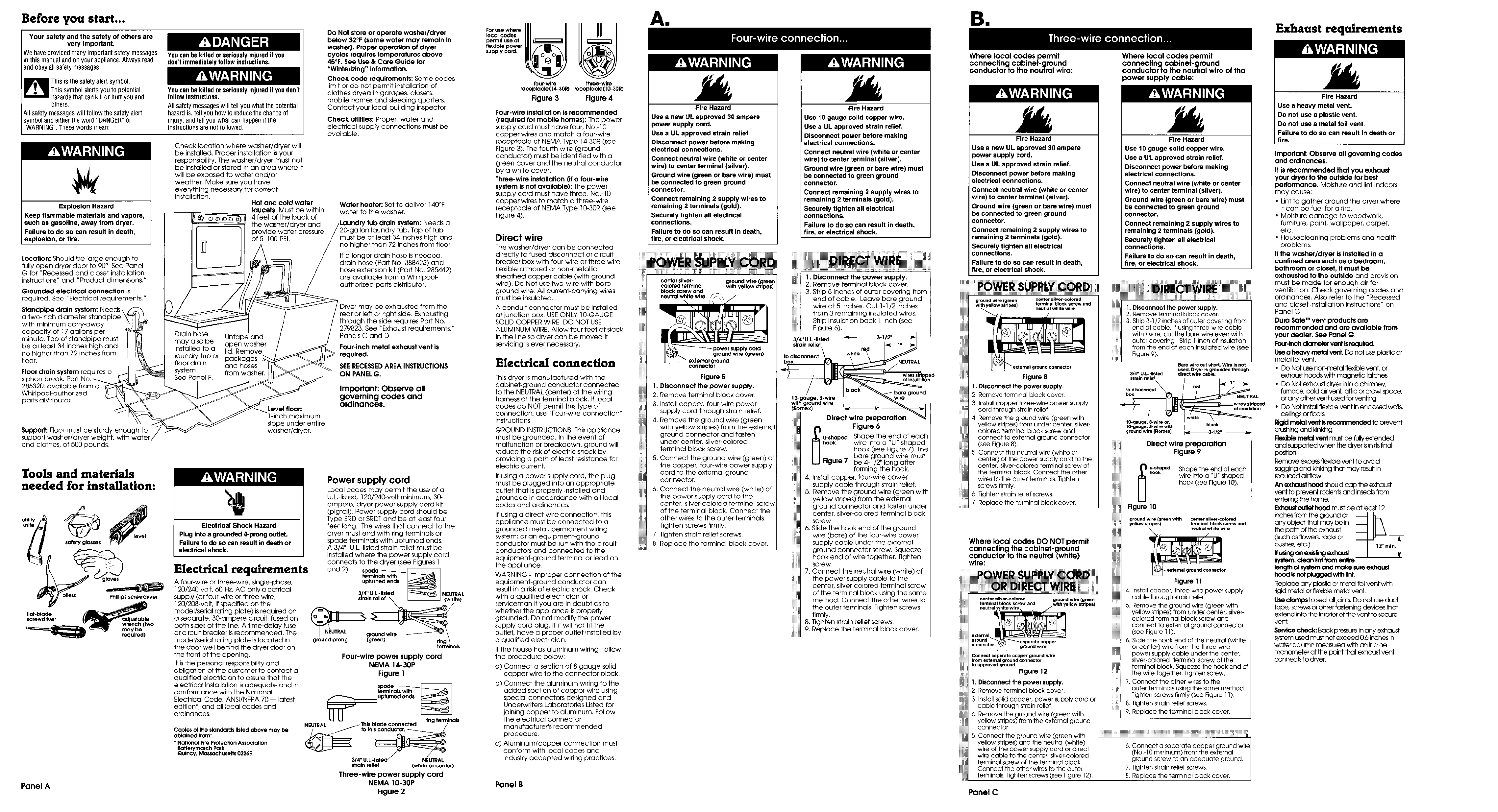
Four-wire installation is recommended
(required for mobile homes): The power
supply cord must have four, No.-] 0
copper wires and match a four-wire
receptacle of NEMA Type 14-30R (see
Figure 3). The fourth wire (ground
conductor) must be identified with a
green cover and the neutral conductor
by a white cover
Three-wire installation (if a four-wire
system is not available): The power
supply cord must have three, No,-1O
copper wires to match a three-wire
receptacle of NEMA Type 10-30R (see
Figure 4).
Direct wire
The washer/dryer can be connected
directly to fused disconnect or circuit
breaker box with four-wire or three-wire
flexible armored or non-metallic
sheathed copper cable (with ground
wire), Do Not use two-wire with bare
ground wire All current-carrying wires
must be insulated
A conduit connector must be installed
at junction box. USE ONLY 10 GAUGE
SOLID COPPER WIRE DO NOT USE
ALUMINUM WIRE. Allow four feet of slack
in the line so dryer can be moved if
servicing is ever necessary.
Electrical connection
Thisdryer is manufactured with the
cabinet-ground conductor connected
to the NEUTRAL (center) of the wiring
harness at the terminal block If local
codes do NOT permit this type of
connection, use "Four wire connection"
Instructions
GROUND INSTRUCTIONS: Thisappliance
must be grounded. Jnthe event of
malfunction or breakdown, ground will
reduce the risk of electric shock by
providing a path of least resistance for
electric current.
If using a power supply cord, the plug
must be plugged into an appropriate
outlet that is properly installed and
grounded in accordance with all local
codes and ordinances,
If using a direct wire connection, this
appliance must be connected to a
grounded metal, permanent wiring
system; or an equipment-ground
conductor must be run with the circuit
conductors and connected to the
equipment ground terminal or lead on
the appliance
WARNING - Improper connection of the
equipment ground conductor can
result in a risk of electric shock Check
with a qualified electrician or
serviceman if you are in doubt as to
whether the appliance is properly
grounded. Do not modify the power
supply cord plug, If it will not fit the
outlet, have a proper outlet installed by
a qualified electrician.
If the house has aluminum wiring, follow
the procedure below:
a) Connect a section of 8 gauge solid
copper wire to the connector block.
b) Connect the aluminum wiring to the
added section of copper wire using
special connectors designed and
Underwriters Laboratories Listed for
joining copper to aluminum Follow
the electrical connector
manufacturer's recommended
procedure.
c) Aluminum/copper connection must
conform with local codes and
industry accepted wiring practices.
Panel B
All
Fire Hazard
Use a new UL approved 30 ampere
power supply cord.
Use a UL approved strain relief.
Disconnect power before making
electrical connections•
Connect neutral wire (white or center
wire) to center terminal (silver).
Ground wire (green or bare wire) must
be connected to green ground
connector•
Connect remaining 2 supply wires to
remaining 2 terminals (gold).
Securely tighten all electrical
connections•
Failure to do so can result in death,
fire, or electrical shock•
Fire Hazard
Use 10 gauge solid copper wire.
Use a UL approved strain relief.
Disconnect power before making
electrical connections.
Connect neutral wire (white or center
wire) to center terminal (silver).
Ground wire (green or bare wire) must
be connected to green ground
connector,
Connect remaining 2 supply wires to
remaining 2 terminals (gold).
Securely tighten all electrical
connections.
Failure to do so can result in death,
fire, or electrical shock.
center silver- ground wire (green
colored terminal with yellow stripes)
block screw and
neuITalwhite wire
power supply cord
ground wire (green)
exTernalground
connector
Figure 5
I. Disconnect the power supply.
2. Remove terminal block cover.
3, rnstall copper, four wire power
supply cord through strain relief.
4. Remove the ground wire (green
with yellow stripes) from the external
ground connector and fasten
under center, silver-colored
terminal block screw.
5. Connect the ground wire (green) of
the copper, tour-wire power supply
cord to the external ground
connector.
6. Connect the neutral wire (white) of
the power supply cord to the
center, silver-colored terminal screw
of the terminal block. Connect the
other wires to the outer terminals.
Tighten screws firmly.
7Tighten strain relief screws.
8 Replace the terminal block cover.
1. Disconnect the power supply.
2, Remove terminal block cover
3. Strip 5 inches of outer covering from
end of cable. Leave bare ground
wire at 5 inches. Cut 1 1/2 inches
from 3 remaining insulated wires
Strip insulation back 1 inch (see
Figure 6).
_a
314" U.L-llstad 3-I
strain relief
to dlsconnecr
box _IEUTRAL
wlressttl pad
bare ground
I 0-gauge, 3-wire wire
wlth ground wlre
(Uomex)
Direct wire preparation
Figure 6
u-shaped Shape the end of each
hook wire into a "U" shaped
hook (see F@ure 7). The
bare groundwire must
Figure 7 be 4-1/2" long after
forming the hook
4. Install copper, four-wire power
supply cable through strain relief.
5. Remove the ground wire (green with
yellow stripes) from the external
ground connector and fasten under
center, silver-colored terminal block
screw
6. Slide the hook end of the ground
wire (bare) of the tour wire power
supply cable under the external
ground connector screw. Squeeze
hook end of wire together. Tighten
screw,
7. Connect the neutral wire (white) of
the power supply cable to the
center, silver colored terminal screw
of the terminal block using the same
method. Connect the other wires to
the outer terminals. Tighten screws
firmly
8. Tighten strain relief screws.
9. Replace the terminal block cover
BII
Where local codes permit
connecting cabinet-ground
conductor to the neutral wire:
Fire Hazard
Use a new UL approved 30 ampere
power supply cord.
Use a UL approved strain relief.
Disconnect power before making
electrical connections.
Connect neutral wire (white or center
wire) to center terminal (silver).
Ground wire (green or bare wire) must
be connected to green ground
connector.
Connect remaining 2 supply wires to
remaining 2 terminals (gold).
Securely tighten all electrical
connections.
Failure to do so can result in death,
fire, or electrtcal shock.
ground wire green oenter sil_er-©olored
with yellow stripes) terminal block screw and
neutral white wire
I
"_. external ground connector
Figure 8
I. Disconnect the power supply.
2 Remove terminal block cover
3 Install copper three-wrro power supply
cord through strain relief
4 Remove the ground wire (green with
yellow stripes) from under center, silver-
colored terminal block screw and
connect to external ground connector
(see Figure 8).
5 Connect the neutral wire (white or
center) of the power supply cord to the
center, silver-colored terminal screw of
the terminal block Connect the other
wires to the outer terminals. Tighten
screws firmly
6 Tighten strain relief screws
7 Replace the terminal block cover,
Where local codes DO NOT permit
connecting the cabinet-ground
conductor to the neutral (white)
wire:
can s a vsr-co ored ground wire (green
_!ii!i! ermna bockSCrewand withye award a
liiiill r_a a wh ewre pe )
iii_iii
iiii?iiioxtarna_
Figure 12
ground sspara a coppe
connector, g ound w re
Connect separate copper ground wire
from external ground canna€ o
to approved ground.
f. Disconnect the power supply.
2 Remove term nab ock cove
In f I I
4 Removethegroundwire(greenwith
3 s a I so Id copper, power supply cord or
cable through strain relief
yellow stripes) from the external ground
connecfo
5 Connect the ground wire (green with
yellow stripes) and the neutral (white)
,_] wire of the power supply cord or direct
I wire cable to the center, silver-co oed
terminal screw of the terminal block
C°nnec __ eh_fehe;w_eSsr°eth_ ,°Ufrer12
. .g g ).
Panel C
Where local codes permit
connecting cabinet-ground
conductor to the neutral wire of the
)ower supply cable:
Fire Hazard
Use 10 gauge solid copper wire•
Use a UL approved strain relief.
Disconnect power before making
electrical connections•
Connect neutral wire (white or center
wire) to center terminal (silver),
Ground wire (green or bare wire) must
be connected to green ground
connector,
Connect remaining 2 supply wires to
remaining 2 terminals (gold).
Securely tighten all electrical
connections•
Failure to do so can result in death,
fire, or electrical shock.
iiiiiiiiil
I. Disconnect the power supply.
2. Remove terminal block cover.
3. Strip 3 1/2 inches of outer covering from
end of cable. If using three wire cable
with I wire, cut the bare wire even with
outer covering Strip 1 inch of insulation
from the end of each insulated wire (see
Figure 9).
Bar_ wire out shod• Wire is not
used. Dryer Is grounl_l thrOugh
3/4" U•L.-Ijs_ed direct "Mre cabS,
strain relief
red
box
ofinsu_on
1O-gauge_ 3-wire or_
10-gauge, 3-wire with
ground "/:,ire(Romaxt
Direct wire preparation
Figure 9
_u-shaped Shape the end of each
hook wire into a "U" shaped
hook (see Figure 10).
Figure 10
ground wire {green with center sliver-colored
yellow stripes) terminal block screw and
n°".":T
r
Figure 11
4. Install copper, three wire power supply
cable through strain relief.
5. Remove the ground wire (green with
yellow stripes) from under center, silver-
colored terminal block screw and
connect to external ground connector
(see Figure 11)
6, Slide the hook end of the neutral (white
or center) wire from the three-wire
power supply cable under the center,
silver-colored terminal screw of the
terminal block. Squeeze the hook end of
the wire together. Tighten screw.
7. Connect the other wires to the
outer terminals using the same method.
Tighten screws firmly (see Figure 11)
8. Tighten strain relief screws
9. Replace the terminal block cover.
I
6 Connect a separate copper ground wire
(No. 10 minimum) from the external J
ground screw to an adequate ground
7 Tighten strain relief screws
8 Replace the terminal block cover.
Exhaust requirements
Fire Hazard
Use a heavy metal vent.
Do not use aplastic vent.
Do not use a metal foil vent.
Failure to do so can result In death or
fire.
Important: Observe all governing codes
and ordinances.
It is recommended that you exhaust
your dryer to the outside for best
performance. Molsture and lint indoors
may cause:
•Lint to gather around the dryer where
it can be fue! for a fire.
• Moisture damage to woodwork,
furniture, paint, wallpaper, carpet,
etc.
• Housecleaning problems and health
problems.
If the washer/dryer is installed in a
confined area such as a bedroom,
bathroom or closet, it must be
exhausted to the outside and prevision
must be made for enough air for
ventilation. Check governing codes and
ordinances Also refer to the "Recessed
and closet installation instructions" on
Panel G
Dura Safe TM vent products are
recommended and are available from
your qealer. See Panel G.
Four-inch dlameler vent b required.
Use a heavy metal vent. Do not use p_sltc or
metal foil vent.
• Do Not use non-metal fle_ble vent, or
exhaust hoods with magnetic latches.
• Do Not exhaust d_/er into o chimney,
fu_ace, cold air vent, attic or crawl space,
or any other vent used for ven_ng
• Do Not installflexible vent in enclosed wall_
ceilings or floors.
I_d _ vent Isreco_n'_ndod to prevent
crushing and Nnking,
Flexible metal vent must be fully extended
and supported when the dryer isin itsfinal
IDO_IlOB.
Remove excess flexi_e vent to avoid
sagging and kinldng that may result in
reduced air flow,
An exhaust hood should cap the exhaust
vent to prevent rodents and insects from
entering the home.
Exhoud out_t hood must be at least 12
inches from the ground or
any object that may be In
the loath of the exhaust
(such as flower_ rocks or
bushe_ etc).
If usingan e_,-fing exhausl
_, oloen Nntfrom entire
le_31h of systemand make sureexlxtust
haad ISnot_wtih#nt
Replace any plastic or metal foil vent w_
_gid rr_tal or flexible metal vent.
Use clamps to seal alljoints. Do not use duct
tape, screws or other fastening devices that
extend into the interior of the vent to secure
vent.
Service check: Back pressure in any exhaust
system used must not exceed 0.6 inches in
water column measured with an incline
manometer at the point that exhaust vent
connects to dryer.
Theexhaust vent can be
routed up, down, left,
right or straight out the
back of the
washer/dryer. Space
requirements are
provided on Panel G
and on the rear panel
Use the strai
you can, to avoid 90°
turns.
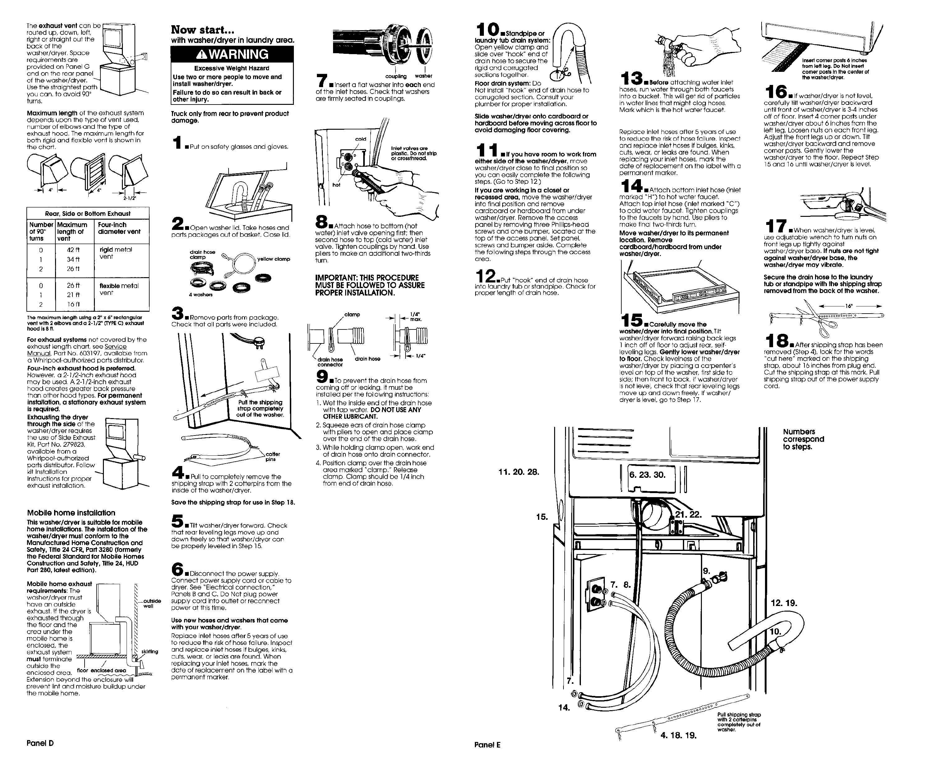
Maximum length of the exhaust system
depends upon the type of vent used,
number of elbows and the type of
exhaust hood. The maximum length for
both rigid and flexible vent is shown in
the chart.
2-1/2"
Rear, Side or Bottom Exhaust
Number Maximum Four-inch
of 90°length of diameter vent
turns vent
0 42 ft rigid metal
1 34 ft vent
2 26 tt
0 26 fl flexible metal
1 21 ft vent
2 16fl
The maximum length usfng a 2" x 6" rectangular
vent wlth 2 elbows and a 2- I12" (TYPE C) exhaust
hood is 8ft.
For exhaust systems not covered by the
exhaust length chart, see Service
Manual, Part No. 603197, availabLe from
a Whirlpool authorized parts distributor
Four-inch exhaust hood ispreferred.
However, a 2-1/2-inch exhaust hood
may be used. A 2-1/2-inch exhaust
hood creates greater back pressure
than other hood types. For permanent
installation, a stationary exhaust system
is required.
Exhausting the dryer
through the side of the
washer/dryer requires
the use of Side Exhaust
Kit, Part No. 279823,
available from a
Whirlpoo!-authorized
parts distributor. Follow
kit Installation -_.
Instructions tar proper
exhaust installation.
Mobile home installation
This washer/dryer is suitable for mobile
home installations. The installation of the
washer/dryer must conform to the
Manufactured Home Construction and
Safety, Title 24 CFR, Part 3280 (formerly
the Federal Standard for Mobile Homes
Construction and Safety, Title 24, HUb
Part 280, latest edition).
Mobile home exhaust r_
requirements: The lJ
washer/dryer must
have an outside [4
exhaust If the dryer is
s\E
exhausted through _
the floor and the
area under the
mobile home is
enclosed, the
exhaust system
must terminate ..... /
outs de the
enclosed area. floor enclosedarea
Extension beyond the enclosure will
--outside
wall
_kirilng
prevent lint and moisture buildup under
the mobile home.
Now start...
with washerldryer in laundry area.
Excessive Weight Hazard
Use two or more people to move and
install washer/dryer.
Failure to do so can result in back or
other injury.
Truck only from rear to prevent product
damage.
iPut on safety glasses and gloves.
nOpen washer lid. Take hoses and
parts packages out of basket. Close lid
drainhose
4washers
B Remove parts from package,
Check that all parts were included.
pins
pletely remove the
shipping strap with 2 cotterpins from the
inside of the washer/dryer,
Save the shipping strap for use in Step 18.
•Tilt washer/dryer forward. Check
that rear leveling legs move up and
down freely so that washer/dryer can
be properly leveled in Step 15.
6• Disconnect the Dower supply
Connect power supply cord or cable to
dryer See "Electrical connection,"
Panels B and C. Do Not plug power
supply cord into outlet or reconnect
power at this time.
Use new hoses and washers that came
with your washer/dryer.
Replace inlet hoses after 5 years of use
to reduce the risk of hose failure. Inspect
and replace inlet hoses if bulges, kinks,
cuts, wear, or leaks are found. When
replacing your inlet hoses, mark the
date of replacement on the label with a
permanent marker
coupling washer
7I Insert a flat washer into each end
of the inlet hoses. Check that washers
are firmly seated in couplings.
cold
Inlet valves are
plastic. Do not strlp
or crossthread,
(hot
water) inlet valve opening first; then
second hose to top (cold water) inlet
valve. Tighten couplings by hand Use
pliers to make an additional t_vo-thirds
turn
IMPORTANT: THIS PROCEDURE
MUST BE FOLLOWED TO ASSURE
PROPER INSTALLATION.
o,°=
"nhOSedrainhose
connechor
•To prevent the drain hose from
coming off or leaking, it must be
installed per the following instructions:
1. Wet the inside end of the drain hose
with tap water DO NOT USE ANY
OTHER LUBRICANT.
2. Squeeze ears of drain hose clamp
with pliers to open and place clamp
over the end of the drain hose.
3. While holding clamp open, work end
of drain hose onto drain connector.
4. Position clamp over the drain hose
area marked "clamp." Release
clamp Clamp should be 1/4 inch
from end of drain hose.
I 0iStandpipeor [f"_
laundry tub drain system: I I I
Open yellow clamp and
s,,0eavorhookendofI I ,"
drain hose to secure the I [ //
rigid and corrugated
sections together
Floor drain system: Do
Not install "hook" end of drain hose to
corrugated section. Consult your
plumber for proper installation.
Slide washer/dryer onto cardboard or
hardboard before moving across floor to
avoid damaging floor covering,
II •If you have room to work from
4
either side of the washer/dryer, move
washer/dryer close to final position so
you can easily complete the following
steps. (Go to Step 12)
If you are working in a closet or
recessed area, move the washer/dryer
into final position and remove
cardboard or hardboard from under
washer/dryer. Remove the access
panel by removing three Phillips-head
screws and one bumper, located at the
top of the access panel. Set panel,
screws and bumper aside. Complete
the following steps through the access
area.
2=Put "hook" end of drain hose
into laundry lub or standpipe. Check for
proper length of drain hose.
_gwater inlet
hoses, run water through both faucets
into a bucket This will get rid of particles
in water lines that might clog hoses
Mark which is the hot water faucet.
Replace inlet hoses after 5 years of use
to reduce lhe risk of hose failure. Inspect
and replace inlet hoses if bulges, kinks,
cuts, wear, or leaks are found When
replacing your inlet hoses, mark the
date of replacement on the label with a
permanent marker,
4•Attach bottom Inlet hose (inlet
marked "H") to hot water faucet.
Attach lop inlet hose (inlet marked "C')
to cold water faucet Tighten couplings
to the faucets by hand, Use pliers to
make final two thirds turn,
Move washer/dryer to its permanent
location. Remove
cardboard/hardboard from under
washer/dryer.
move the
washer/dryer into final position.Tilt
washer/dryer forward raising back legs
1 inch off of floor to adjust rear, self
leveling legs. Gently lower washer/dryer
tofloor,Check levelness of the
washer/dryer by placing a carpenter's
level on top of the washer, first side to
side; then flont to back. If washer/dryer
is not level, check that rear leveling legs
move up and down freely. If washer/
dryer is level, go to Step 17.
the washer/dryer.
6. If washer/dryer is not level,
carefully tilt washer/dryer backward
until front of washer/dryer is 3-4 inches
off of floor. Insert 4 corner posts under
washer/dryer about 6 inches from the
left leg. Loosen nuts on each front leg.
Adjust the front legs up or down. Tilt
washer/dryer backward and remove
corner posts. Gently lower the
washer/dryer to the floor. Repeat Step
15 and 16 until washer/dryer is level.
7nWhen washer/dryer is level,
use adjustable wrench to turn nuts on
front legs up tightly against
washer/dryer base. If nuts ore not tight
against washerldryer base, the
washer/dryer may vibrate.
Secure the drain hose to the laundry
tub or standpipe with the shipping strap
removed from the back of the washer.
1t iBlaAfter shipping strap has been
removed (Step 4), look for the words
"cut here" marked on the shipping
strap, about 16 inches from plug end,
Cut the shipping strap at this mark. Pull
shipping strap out of the power suppry
cord.
INumbers
correspond
to steps.
12. 19.
Pull shipPing strap
with 2 cotterplns
completely out of
washer.
4. 18. 19.
Panel D Panel E
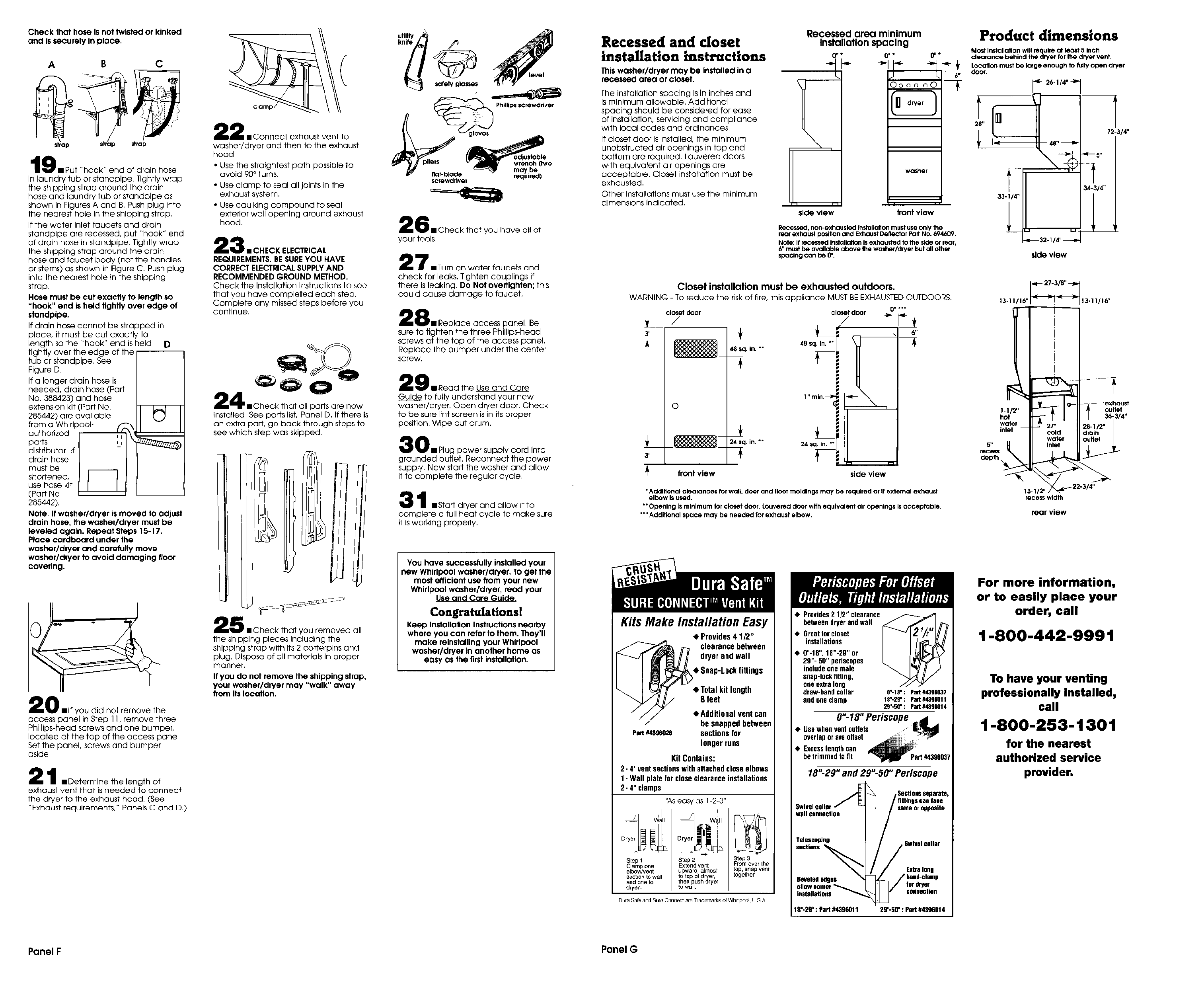
Check that hose is not twisted or kinked
and is securely in place.
A B C
str strap
9mPut "hock" end of drain hose
in laundry tub or standpipe Tightly wrap
the shipping strap around the drain
hose and laundry tub or standpipe as
shown in Figures A and B Push plug into
the nearest hole in the shipping strap
If the water inlet faucets and drain
standpipe are recessed, put "hook" end
of drain hose in standpipe. Tightly wrap
the shipping strap around the drain
hose and faucet body (not the handles
or stems) as shown in Figure C. Push plug
into the nearest hole in the shipping
strap
Hose must be cut exactly to length so
"hook" end is held tightly over edge of
standpipe.
If drain hose cannot be strapped in
place, it must be cut exactly to
length so the "hook" end is held D
tightly over the edge of the
tub or standpipe. See
Figure D.
If a longer drain hose is
needed, drain hose (Part
No. 388423) and hose
extension kit (Part NO.
285442) are available
from a Whirl )col- /_r
authorized ii
parts ,,
distributor, if
drain hose
must be
shortened, _use hose kit
(Part No.
285442)
Note: If washer/dryer is moved Io adjust
drain hose, the washer/dryer must be
leveled again. Repeat Steps 15-17.
P#ace cardboard under the
washer/dryer and carefufly move
washer/dryer to avoid damaging floor
covering.
AA
ZO • IfyOU did not remove the
access panel inStep 1I,remove three
Phillips-head screws and one bumper,
located at the top of the access panel
Set the panel, screws and bumper
aside
1 _Determine the length of
exhaust vent that is needed to connect
the dryer to the exhaust hood. (See
"Exhaust requirements," Panels C and D,)
2• Connect exhaust vent to
washer/dryer and then to the exhaust
hood
• Use the straightest path possible to
avoid 90°turns.
• Use clamp to seal all joints in the
exhaust system.
• Use caulking compound to seal
exterior wall opening around exhaust
hood,
3•CHECK ELECTRICAL
REQUIREMENTS.BE SUREYOU HAVE
CORRECT ELECTRICALSUPPLYAND
RECOMMENDED GROUND METHOD.
Check the Installation Instructions to see
that you have completed each step
Complete any missed steps before you
continue,
installed See parts list, Panel D. If there is
an extra part, go back through steps to
see which step was skipped
5• Check that you removed all
the shipping pieces including the
shipping strap with its 2 cotterpins and
plug, Dispose of all materials in proper
manner.
If you do not remove the shipping strap,
your washer/dryer may "walk" away
from its location•
uOlITY
safetyglasses
gloves " Phiiiips screwdriver
e_quim<l)
,_rewdtJvef
6• Check that you have all of
your tools.
7• Turn on water faucets and
check for leaks. Tighten couplings if
there is leaking. Do Not oveffighten; this
could cause damage to faucet.
8mReplace access panel Be
sure to tighten the three Phillips-head
screws at the top of the access panel.
Replace the bumper under the center
screw.
9_Read the Use and Care
Guide to fully understand your new
washer/dryer. Open dryer door. Check
to be sure lint screen is in its proper
position. Wipe out drum.
0 • Plug power supply cord into
grounded outlet. Reconnect the power
supply. Now start the washer and allow
it to complete the regular cycle
1_Stad dryer and allow it to
complete a full heat cycle to make sure
it is working properly.
You have successfully installed your
new Whirlpool washer/dryer. To get the
most efficient use from your new
Whirlpool washer/dryer, read your
Use and Care Guide.
Congratulations!
Keep Installation Instructions nearby
where you can refer to them• They'll
make reinstalling your Whirlpool
washer/dryer in another home as
easy as the first installation•
Recessed and closet
installation instructions
This washer/dryer may be installed in o
recessed area or closet.
The installation spacing is in inches and
is minimum allowable. Additional
spacing should be considered for ease
of installation, servicing and compliance
with local codes and ordinances
If closet door is installed, the minimum
unobstructed air openings in top and
botlom are required. Louvered doors
with equivalent air openings are
occeptoPke. Closet instaUation must be
exhausted.
Other Installations must use the minimum
dimensions indicated
Recessed area minimum
installation spacing
0_* 0"* O"*
Oooo cO
Rwasher
side view front view
Product dimensions
Recessed, non-exhausted installation must use only the
rear exhaust po_fion and Exhaust Degector Part NO. 694609.
Note: If recessed installotlan is exhausted to the slde or rear,
6" must be available above the washerldryer but all other
spacing can be 0".
Most InstallaSon will require at least Sinch
clearance behind the dryer for the dryer vent.
_- _ Locanon must be large enough to fully open dryer
Idoor.
6'r
+ a.,,.-q
72-3/4"
side view
Closet installation must be exhausted outdoors.
WARNING - To reduce the risk of fire, this appliance MUST BEEXHAUSTED OUTDOORS.
closetdoor
/
3"
o
48 $q. in. *"
+
front view side view
• Additional clearances for wag, door ancl flOOr moldlngs may be requ&red or if external exhaust
elbow is used.
** Opening Is mlnlmum for closet door. Louvered door with equivalent air openings is acceptable.
***Additional space may be needed for exhaust elbow,
13.11/16'I _a_ 13.111)6 -
5,,
recess
depth
1-I12"
hot
watel
inlet
exhaust
ouOet
13-II
recess width
rear view
Kits Make Installation Easy
•Provides 41/2"
clearance between
dryer and wall
eSnap-Lockfiflings
Part #4396028
4.Total kit length
8 feet
4)Additional vent can
be snapped between
sections for
Iongerruns
Kit Contains:
2- 4' ventsectionswith attachedcloseelbows
1- Wall platefor closeclearanceinstallations
2- 4" clamps
"Aseasy as 1-2-3"
,II
--_ Wall _ _
Step 1Step 2Step 3
Clamp one Extend vent From over the
elbowlvent upward, almost top, snap vent
section to wall to top of dryer, together.
arid one to then push dryer
dryer, to wall.
Dura Safe and Sure Oo,lrle¢_ are TrademarKs of WhirlpOOl U S A
• Provides 2 1/2" clearance
between dryerand wall
•Great for closet
installations
• 0"-18", 16"-2G" or
29"- 50" periscopes
include one male
snap-lockfitting,
one extra long
draw-band collar
and one clamp
0%18": Part #4396037
15'*-26" : Part #4396011
2S"-56" : Part #4396th 4
0"- 18" Periscope
Usewhenventoutlets _
overlapor are offset _
betrimmedto lit rt#4396037
18"-29" and 29"-50" Periscope
Swivelcollar
wail connection
,Sectionsseparate,
fittingscanface
sameor opposite
Telescoptns , Swivelcollar
aevelededges
installations
18"-2_': Pan #4396011
Extra long
for dryer
COllnoction
29"- 55" : Pan #4396014
For more information,
or to easily place your
order, call
1-800-442-9991
To have your venting
professionally installed,
call
1-800-253-1301
for the nearest
authorized service
provider.
Panel F Panel G
If washer/dryer does
not operate properly..•
Check the following to be sure that:
1. Electriqal supply is connected.
2. House fuse or circuit breaker is intact
and tight,
3. Washer lid or dryer door is closed.
4. Controls are set in a running or "ON"
position.
5. Dryer staff button has been firmly
pushed.
6. Make sure shipping strap has been
completely removed and was used to
secure the drain hose to the laundry
tub or standpipe.
When moving the
washer/dryer...
• Disconnect the power supply cord,
then tape securely to the
washer/dryer.
• Tape the drum to the front panel.
Tape the lint screen in place. Tape
the dryer door closed.
• Wedge a blanket between the tub
ring and cabinet top to restrict tub
movement.
• Turn front leveling legs all the way in.
Part No. 3397616 Rev. B
© 2000 Whirlpool Corporation
® Registered Trademark of Whirlpool, U,S.A,
If you need assistance...
The Whirlpool Customer Interaction Center
win answer any questions about operating
or maintaining your washer/dryer not
covered in the Installation Instructions. The
Whirlpool Customer Interaction Center is
open 24 hours a day, 7 days a week, Just
dial 1-800_253-1301 -- the call is free.
When you call, you will need the
washer/dryer model number and serial
number. Both numbers can be flBund on the
model/serial rating plate located in the
door well behind the dryer door on front of
opening.
Prepared by Whirlpool Corporation,
Benton Harbor, Michigan 49022
If you need service...
In the event that your Whirlpool
appliance should need service, call the
dealer from whom you purchased the
appliance or a Whirlpool-authorized
service company. A Whirlpool-
authorized service company is listed in
the Yellow Pages of your telephone
directory under "Appliances-
Household -- Major -- Service and
Repair." You can also obtain the service
company's name and telephone
number by dialing, free, within the
continental United States, the Whirlpool
Customer Interaction Center telephone
number, 1-800-253-1301. A special
operator will tell you the name and
number of your nearest Whirlpool-
designated service company.
Maintain the quality built into your
Whirlpool appliance -- call a Whirlpool-
designated service company.
Printed in U.S.A,
