White Rodgers F145RF-1328 Wireless Remote Temperature Sensor User Manual 37 6426
White-Rodgers Wireless Remote Temperature Sensor 37 6426
User Manual
www.white-rodgers.com
F145RF-1328F145RF-1328
F145RF-1328F145RF-1328
F145RF-1328
Indoor Wireless Remote SensorIndoor Wireless Remote Sensor
Indoor Wireless Remote SensorIndoor Wireless Remote Sensor
Indoor Wireless Remote Sensor
PART NO. 37-6836A
0650
INSTALLATION INSTRUCTIONS
DESCRIPTION
F145RF-1328 Indoor Wireless Remote Sensor
SPECIFICATIONS
Operating Range: (based on thermostat range)
F145RF-1328 Indoor Model . . . . . . . . . . . . . . . . . . 40 to 99°F
Operating Humidity Range . . . . . . . . . . . . . . . . . . . 0 to 90% RH (non-condensing)
Maximum Distance from Thermostat . . . . . . . . . . . 150 feet
Color . . . . . . . . . . . . . . . . . . . . . . . . . . . . . . . . . . . . Classic White
Dimensions . . . . . . . . . . . . . . . . . . . . . . . . . . . . . . 2.611"H x 4.269"W x 0.875"D
Compatible with all White-Rodgers wireless remote sensing thermostats
Changes or modifications not expressly approved by
White-Rodgers could void the user’s authority to
operate the equipment.
CAUTION
!
Operator: Save these instructions for future use!
FAILURE TO READ AND FOLLOW ALL INSTRUCTIONS CAREFULLY BEFORE INSTALLING OR OPERATING THIS
CONTROL COULD CAUSE PERSONAL INJURY AND/OR PROPERTY DAMAGE.
This device complies with Part 15 of the FCC Rules. Operation is subject to the following two conditions: (1) This
device may not cause harmful interference, and (2) this device must accept any interference received, including
interference that may cause undesired operation.
This is a low cost microcomputer based remote temperature
sensor, with a Liquid Crystal Display utilizing a single
integrated chip radio transmitter to transmit temperature and
associated information to the host-controlling thermostat.
Features:
- The ability to display sensed temperature from -40°F to
140°F
- User selected temperature offset + 4°F with up to 8 hours
hold time
- Calibrate Ambient Temperature + 4°F
- Selectable Fahrenheit/Celsius Display.
- Keypad Lockout.
- Comfort Adjust Bar Graph indicator.
- Indoor temperature sensors.
- Low battery indicator.
- Disable display temperature.
- Green display backlight.
- Transmitter multiple channel operation (10 channels are
provided).
- Installer learning mode can be used to bind the sensor’s
transmitter with the thermostat’s receiver and verify the
maximum allowable range.
- A non-volatile memory provided to save the user’s settings
without batteries.
2
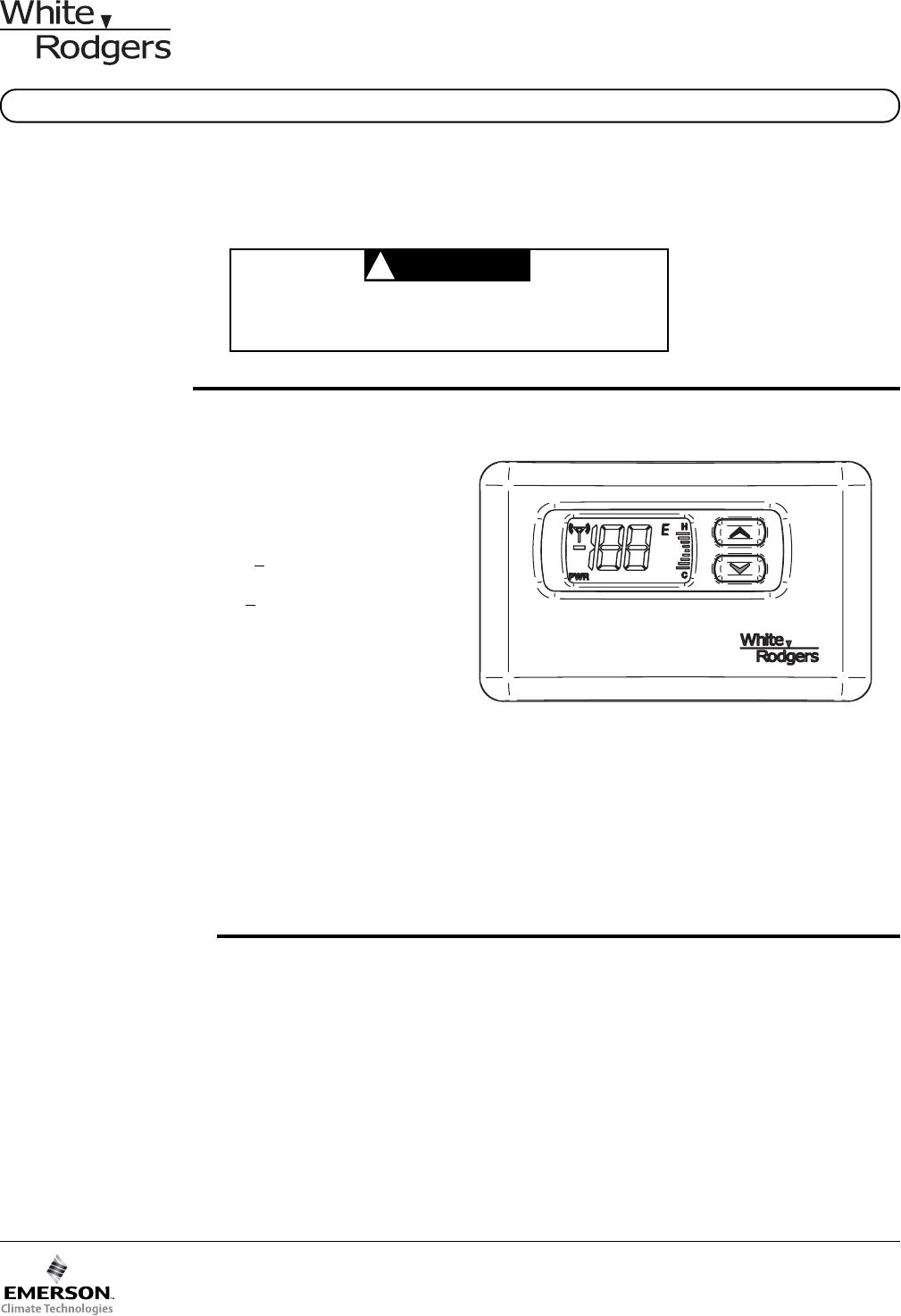
Before you begin configuring your wireless indoor sensor,
you should be familiar with its features and with the display
and the location and operation of the sensor buttons. Your
thermostat consists of two parts: the sensor cover and the
base.
The Display
INSTALLATION
INDOORS SELECT SENSOR LOCATION
Proper location insures that the remote sensor will provide a
comfortable home or building temperature. Observe the
following general rules when selecting a location:
2
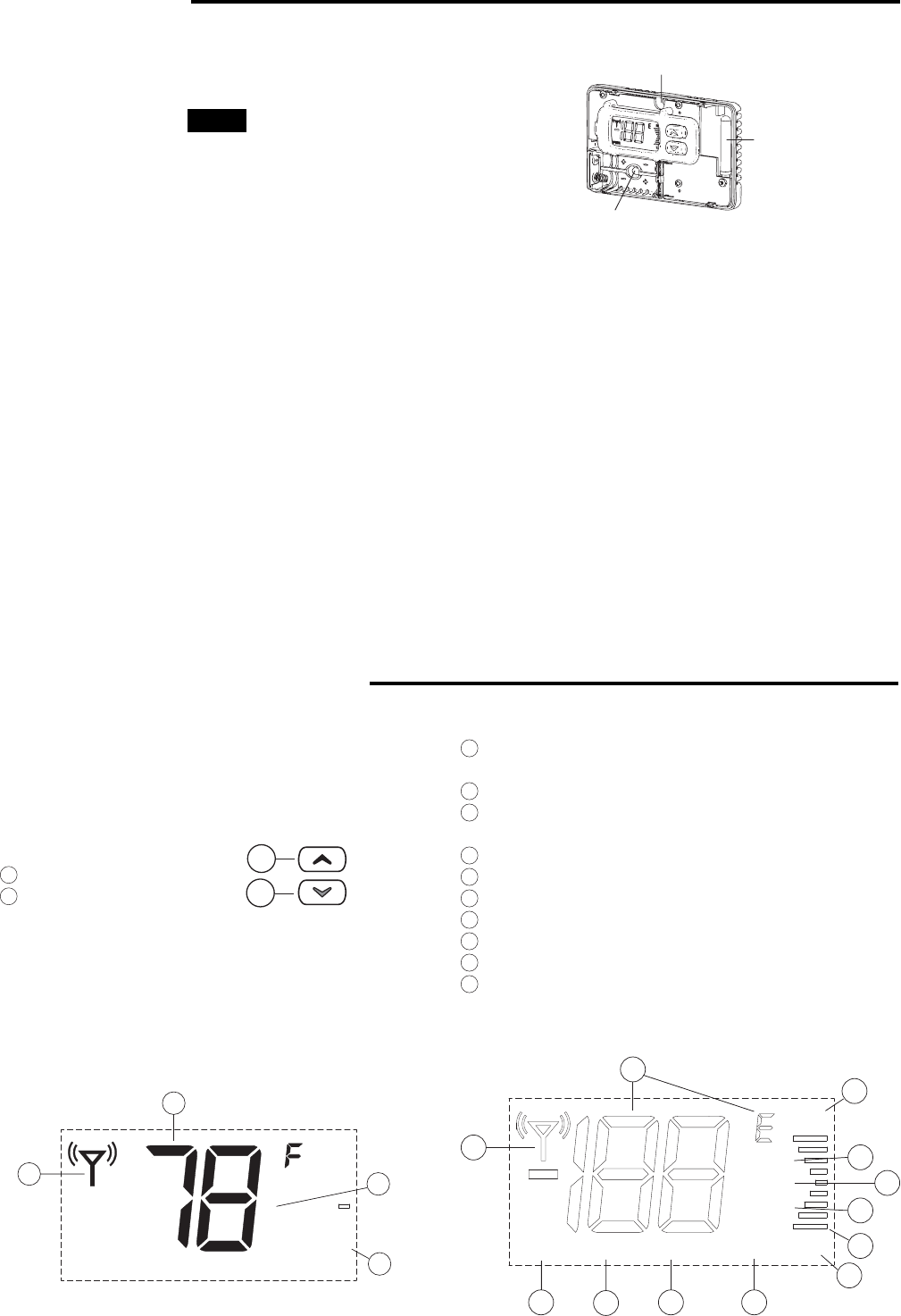
ATTACH WIRELESS REMOTE SENSOR BASE TO WALL
CHECK WIRELESS INDOOR SENSOR OPERATION
Refer to the thermostat user manual for complete details.
1. Remove the packing material from the sensor. Gently
pull the front cover straight off the base. Forcing or prying
on the sensor will cause damage to the unit.
2. Place base on wall and mark mounting hole locations
using base as a template.
3. Move base out of the way. Drill mounting holes.
4. Fasten base loosely to wall, as shown above, using two
mounting screws. Place a level against bottom of base,
adjust until level, and then tighten screws. (Leveling is for
appearance only and will not affect sensor operation.) If
you are using existing mounting holes, or if holes drilled
are too large and do not allow you to tighten base snugly,
use plastic screw anchors to secure subbase sensor to
operate properly with your system.
5. Place two AAA batteries in the batteries holder base
location.
6. Replace the cover by lining up the cover with the base
and press until the cover snaps onto the base.
1
2
The Thermostat Buttons
1Raises the setting.
2Lowers the setting.
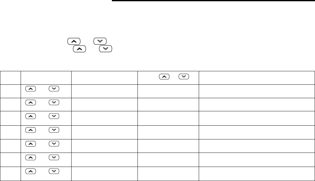
3
the sensed temperature from –40 to 140°F with
°F and °C indicator
4
Channel identification A B C O indicator
5
9 bar comfort adjust bar graph with H (hotter) and
C (cooler)
6
Transmission occurrence indicator
7
Key pad lockout indicator
8
Calibrate temperature offset indicator
9
Learn mode activated Indicator
10
Low batteries indicator
11
Temperature offset is used when hold time is active
12
Shows PWR with on to indicate normal operation with
display OFF
DISPLAY QUICK REFERENCE
A
o
64
3
5
ABCO
LOCK
LEARN
BATT
PWR HLD
H
CALIB
C
o
11 9
6
8
7
10
5
4
12
3
5
5
Normal Operation Configuration Items
Antenna
Mounting Hole
Mounting Hole
1. The remote sensor can be located a maximum of 150
feet from the thermostat.
2. Locate sensor about 5 ft. above the room floor level.
3. Install sensor on a partitioning wall, not on an outside
wall.
4. Never expose sensor to direct light from lamps, sun,
fireplaces or any temperature radiating equipment.
5. Avoid locations close to windows, adjoining outside
walls, or doors that lead outside.
6. Avoid locations close to air registers or in the direct path
of air from them.
7. Make sure there are no electrical wires, metal, pipes or
duct work in that part of the wall chosen for the sensor
location.
8. Avoid locating the sensor on a concrete wall, junction
box or metal plate.
9. Never locate sensor in a room that is normally warmer or
cooler than the rest of the home (such as the kitchen) or
building.
10. Avoid locations with poor air circulation, such as behind
doors or in alcoves.
11. In the home, the bedroom, the living or dining room is
normally a good location, provided there is no cooking
range or refrigerator on opposite side of wall.
NOTE
This sensor must be attached to a wall during operation.
Moving the sensor around is strictly prohibited.
3
CONFIGURATION MENUS
The configuration menus allow you to set certain thermostat operating characteristics to your system or personal requirements.
Two configuration menus are available User Configuration Menu and Installer Configuration Menu.
User Configuration Menu
In the normal mode, press and keys at the same time momentarily to enter the User menu. To scroll through the
menu momentarily press the and keys at the same time. To exit the menu scroll through all menu items. If no
buttons are pushed for 3 minutes, the control will return to normal operation.
Displayed Press or
Step Press button(s) (factory default) to select Comments
1 and LOCK on Select keypad lockout OFF or ON
(OF)
2 and HLD 1 to 8 hrs Select temporary adjust temperature
(4h) in 1 hour increments hold time
3 and CALIB 1-4 bars (1°-4°) C to Select temperature display adjustment
(Sensed Temperature) 1-4 bars (1°-4°) H higher or lower
4 and dFOF Select display temperature OFF or ON
(on)
5 and dL OF Select display backlight OFF or ON
(on)
6 and oFoC Select temperature display to F or C
(Sensed Temperature)
7 and _____ _____ Exit user menu and return to normal
operation
User configuration menu
The User Configuration Menu table summarizes the configuration options. An explanation of each option follows.
1) Select keypad lockout OFF or ON – Selecting LOCK ON will cause the keypads to lock in the normal operation mode. This
will prevent the user from adjusting the sensed temperature in the normal operation. Selecting LOCK OFF will cause the
keypads to unlock in the normal operation mode. Display will indicate LOCK in the display when the keypad is in lockout.
2) Select temporary adjust temperature hold time – Select the length of time for the temporary temperature adjustment.
Hold time default is 4 hours and can be set from 1 to 8 hours in 1 hour increments.
3) Select temperature display adjustment higher or lower – allows you to adjust the room temperature display 1° to 4° higher
or lower. Your sensor was accurately calibrated at the factory but you have the option to change the display temperature to
match your previous sensor.
4) Select display temperature OFF or ON – Selecting OFF allows you to disable displaying the sensed temperature in the normal
operation. Instead the sensor will display PWR with the word (on) to indicated normal operation.
5) Select display backlight OFF or ON -. The display backlight improves display contrast in low lighting conditions. Selecting
dL ON will keep the light on for a short period of time after any key is pressed. Selecting OFF will keep the light off.
6) Select temperature display to oF or oC - Changes the display readout to Celsius or Fahrenheit as required.
Installer Configuration Menu
In the normal mode, press and keys for a minimum of five seconds at the same time to enter the Installer menu.
To scroll through the menu momentarily press the and keys at the same time. To exit the menu scroll through all
menu items. If no buttons are pushed for 3 minutes, the control will return to normal operation.
St. Louis, Missouri
www.white-rodgers.comwww.white-rodgers.com
www.white-rodgers.comwww.white-rodgers.com
www.white-rodgers.com
White-Rodgers is a division
of Emerson Electric Co.
The Emerson logo is a
trademark and service mark
of Emerson Electric Co.
Displayed Press or
Step Press button(s) (factory default) to select Comments
1 and LEARN on Select learn mode OFF or ON
(OF)
2 and CH B, C, O Select sensor identification as A, B, C or O
(A)
3 and C1 through 9 Select transmitter frequency offset
(0)
4 and _____ _____ Exit installer menu and return to normal
operation
Installer Configuration Menu
The Installer Configuration Menu table summarizes the configuration options. An explanation of each option follows.
1) Select learn mode OFF or ON – Selecting LEARN on enables the sensors learning mode. In the learning mode the sensor
will transmit the information once every 10 seconds for a period of 10 minutes. The LEARN icon will be displayed in normal
operation during the learning mode. The transmitter icon will be displayed for a short period of time with each transmission.
For more information about the learning mode, please refer to the thermostat’s user manual.
2) Select sensor identification from A to O – For multiple sensors systems, each sensor must have a designated identification.
For indoor sensors you may select A, B or C. For outdoor sensor you must select O.
3) Select transmitter frequency offset – The sensor’s transmitter operates on 418MHz radio frequency by default. Interfer-
ence may occur if another device or equipment operates on the same frequency. The interference may degrade the
communications between the sensor and the thermostat. To avoid interference, you may select a different radio frequency
for your sensor. This menu item allows you to select a radio frequency offset from 1 to 9MHz from the base frequency. For
example; if the you selected an offset of 4, the transmitter radio frequency will be 418MHz + 4MHz = 422MHz. Note that
the sensor’s transmitter and the thermostat’s receiver must operate on the same frequency to communicate. To change
thermostat’s receiver frequency please refer to the thermostat’s user manual.
SYSTEM DIAGNOSTICS
1) Low Battery power: The sensor will display the word LO along with BATT icon to indicate a low battery power condition.
The batteries must be replaced to ensure a proper sensor performance. For optimum performance, we recommend
replacing batteries once a year with fresh “AAA” Energizer ® alkaline batteries.
2) Bad wireless remote temperature Sensor: If the sensor’s temperature device fails the sensor will display E1. If the sensor’s
transmitter device fails the sensor will display E0. In both cases the sensor must be replaced.
OPERATION
The sensor monitors the temperature and sends information to the thermostat. Updated information is sent to the thermostat
when the temperature changes 3/16 degree or more from the last update.
The room temperature can be adjusted hotter or cooler without changing the thermostat setpoint by pressing or
on the remote. The temperature can be adjusted 1° to 4°F for the length of time set for temporary hold in the User configura-
tion menu. When the or keys are pressed to adjust the temperature the comfort adjust bar graph will show 1 to 4
bars up with H to indicate hotter or 1 to 4 bars down with C to indicate cooler.