White Rodgers 1F89 211 80 Series Heat Pump Thermostat Installation And Operation Instructions 1F89_211_37 6233G
2015-03-28
: White-Rodgers White-Rodgers-1F89-211-White-Rodgers-80-Series-Heat-Pump-Thermostat-Installation-And-Operation-Instructions-676967 white-rodgers-1f89-211-white-rodgers-80-series-heat-pump-thermostat-installation-and-operation-instructions-676967 white-rodgers pdf
Open the PDF directly: View PDF ![]() .
.
Page Count: 8
CAUTION
!
To prevent electrical shock and/or equipment damage,
disconnect electric power to system at main fuse or
circuit breaker box until installation is complete.
This thermostat is intended for use with a low voltage system;
do not use this thermostat with a line voltage system. If in doubt
about whether your wiring is millivolt, line, or low voltage, have
it inspected by a qualified heating and air conditioning contrac-
tor or electrician.
Do not exceed the specification ratings.
All wiring must conform to local and national electrical codes
and ordinances.
This control is a precision instrument, and should be handled
carefully. Rough handling or distorting components could cause
the control to malfunction.
FAILURE TO READ AND FOLLOW ALL INSTRUCTIONS CAREFULLY
BEFORE INSTALLING OR OPERATING THIS CONTROL COULD CAUSE
PERSONAL INJURY AND/OR PROPERTY DAMAGE.
DESCRIPTION
Your new White-Rodgers Digital Thermostat uses the
technology of a solid-state microcomputer to provide precise
temperature control.
Features:
• Simultaneousheatandcoolsetpointstorage
• Setpointstorageincaseofpowerloss
• Pre-settemperaturecontrol
• LCDcontinuouslydisplayssetpointandroomtemperature
• ContinuousBacklitdisplayoption
• °F/°Cconvertibility
• Temperaturerange45°to90°F
• R,C,Y,W2,G,O/B,E,andLterminalsforsingleortwo-
transformer systems
• Optional"AA"batteriestoprovidecontinuoustemperature
displayduringlossofACpower
SPECIFICATIONS
ELECTRICAL DATA
Electrical Rating:
20to30VAC50/60Hz.orD.C.
0.05to1.0Amps(Loadperterminal)
1.5 Amps Maximum Total Load(Allterminalscombined)
THERMAL DATA
Setpoint Temperature Range:
45°Fto90°F(7°Cto32°C)
Operating Ambient Temperature Range:
32°Fto105°F
Operating Humidity Range:
0to90%RH(non-condensing)
Shipping Temperature Range:
-4°Fto149°F
APPLICATIONS
Forusewith:
• Standardheatpumpsystemswithelectric,gasoroilAux
heatwith24VACHOTandCOMMONavailable
• Single-stageheatpumpsystemswithnoAuxheatwith
24VACHOTandCOMMONavailable
DO NOT USE WITH:
• Millivoltsystems
• Systemsexceeding30VACand1.5amps
• 3-wirezonedhydronicheatingsystems
1F89-211
Non-programmableElectronicDigital
HeatPumpThermostat
INSTALLATION AND
OPERATION INSTRUCTIONS
PRECAUTIONS
WARNING
!
Do not use on circuits exceeding specified voltage.
Higher voltage will damage control and could cause
shock or fire hazard.
Do not short out terminals on gas valve or primary
control to test. Short or incorrect wiring will damage
thermostat and could cause personal injury and/or
property damage.
Thermostat installation and all components of the
system shall conform to Class II (current limited)
circuits per the NEC code. Failure to do so could cause
a fire hazard.
Operator: Save these instructions for future use!
PART NO. 37-6233G
Replaces37-6233F
1502
www.white-rodgers.com
www.emersonclimate.com
2
INSTALLATION
REMOVE OLD THERMOSTAT
1. Shutoffelectricityatthemainfuseboxuntilinstallationis
complete.Ensurethatelectricalpowerisdisconnected.
2. Removethefrontcoveroftheoldthermostat.With wires
still attached, remove wall plate from the wall. If the old
thermostat has a wall mounting plate, remove the thermostat
and the wall mounting plate as an assembly.
3. Identify each wire attached to the old thermostat using
the labels enclosed with the new thermostat.
4. Disconnect the wires from old thermostat one at a time.
DO NOT LET WIRES FALL BACK INTO THE WALL.
5. Installnewthermostatusingthefollowingprocedures.
ATTENTION!
Thisproductdoesnotcontainmercury.However,thisproduct
may replace a unit which contains mercury.
Do not open mercury cells. If a cell becomes damaged, do
not touch any spilled mercury. Wearing nonabsorbent gloves,
takeup thespilledmercuryandplaceintoacontainerwhich
can be sealed. If a cell becomes damaged, the unit should be
discarded.
Mercurymustnotbediscardedinhouseholdtrash.Whentheunit
this product is replacing is to be discarded, place in a suitable
container. Refer to www.thermostat-recycle.org for location to
send product containing mercury.
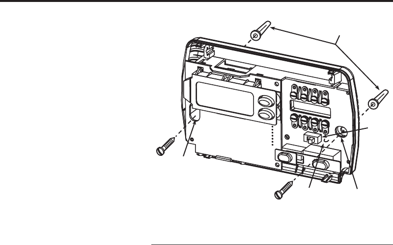
ATTACH THERMOSTAT BASE TO WALL
1. Removethepackingmaterialfromthethermostat.Gentlypullthe
coverstraightoffthebase.Forcingorpryingonthethermostat
will cause damage to the unit.
2. Connectwiresbeneathterminalscrewsonbaseusingap-
propriatewiringschematic(seegs.2through4).
3. Placebaseoverholeinwallandmarkmountingholeloca-
tions on wall using base as a template.
4. Movebaseoutoftheway.Drillmountingholes.
5. Fastenbaselooselytowall,asshowning.1,usingtwo
mounting screws. Place a level against bottom of base,
adjustuntillevel,andthentightenscrews.(Levelingisfor
appearanceonlyandwillnotaffectthermostatoperation.)
If you are using existing mounting holes, or if holes drilled
are too large and do not allow you to tighten base snugly,
use plastic screw anchors to secure subbase.
6. Pushexcesswireintowallandplugholewithare-resistant
material(suchasberglassinsulation)topreventdraftsfrom
affecting thermostat operation.
ELECTRIC/GAS JUMPER (Fan Option)
Read the following information before clipping the nonelectric
heat jumper. If you are unsure of your application, contact a
qualified service person.
Ifyouremergencyorauxiliarysystemwillenergizetheblower,then
jumper,W904,onthethermostatbasemustbecut(seeg.1).
If your emergency or auxiliary heat system requires that the
thermostatenergizethefancircuit,donotcutjumperW904.
OPTIONAL BATTERIES
Withtwo"AA"batteriesinstalled,yourthermostatwillcontinu-
ouslydisplaythetemperatureduringalossofACpower.
O/B TERMINAL SWITCH SELECTION
The O/B switch on this thermostat is factory set to the “O”
position. This will accommodate the majority of heat pump ap-
plications,whichrequirethechangeoverrelaytobeenergized
inCOOL.Ifthethermostatyouarereplacingortheheatpump
beinginstalledwiththisthermostatrequiresa“B”terminal,to
energizethechangeoverrelayinHEAT,theO/Bswitchmustbe
movedtothe“B”position.
Figure 1. Thermostat Base
Mounting
hole
Mounting
hole
Electric/Gas
jumper
(W904)
O/B
switch
Screwanchors
W904
3
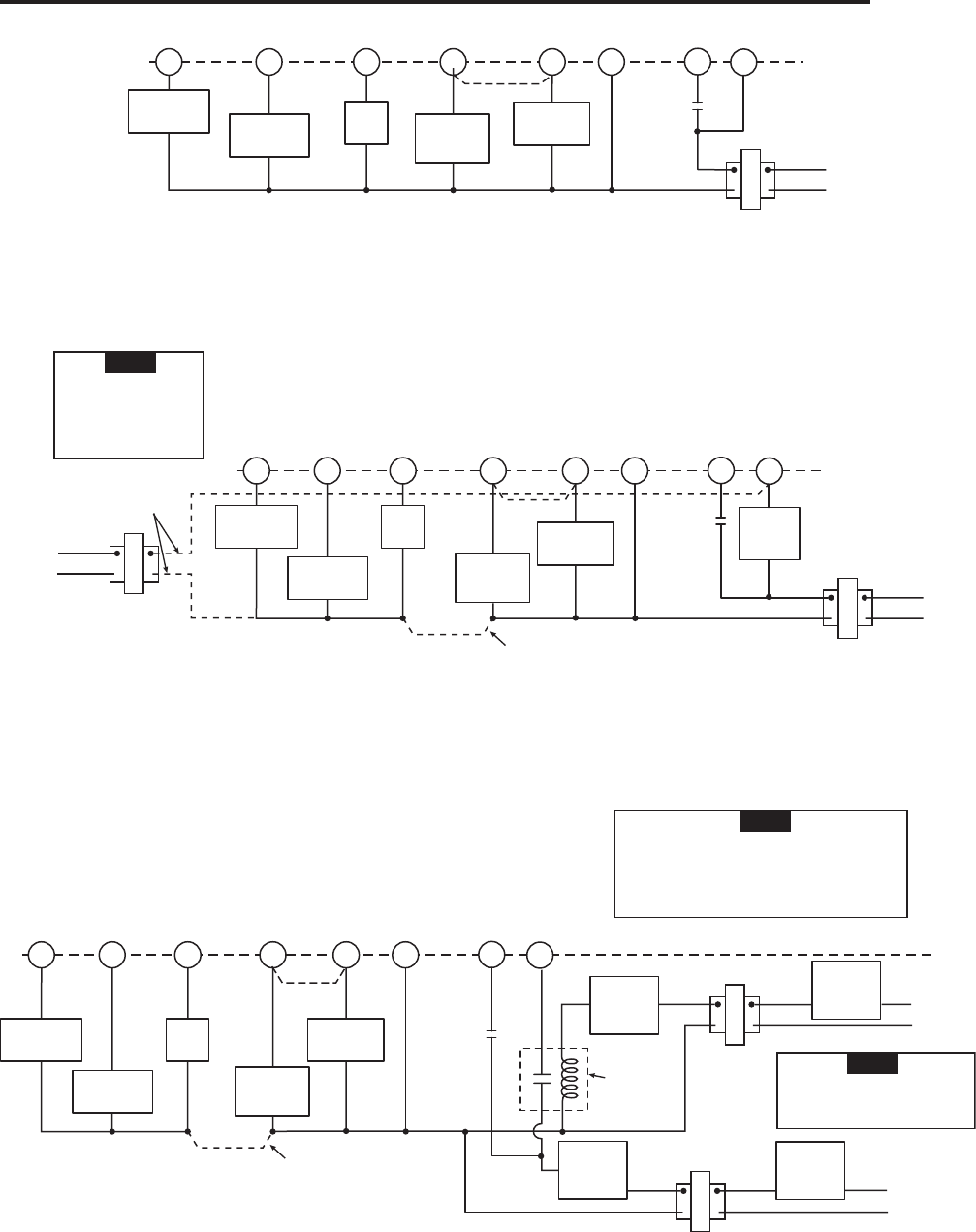
WIRING
LR
E
24 VAC 120 VAC
Hot
SYSTEM
MONITOR
SWITCH
Neutral
THERMOSTAT
SYSTEM
G W2
Figure 2. Typical wiring diagram for single transformer systems
TRANSFORMER
(Class II current limiting)
Changeover
Relay*
CYO/B
Compressor
Contactor
*ChangeoverRelayisenergizedinCOOLwhenO/Bswitchisinthe“O”position
ChangeoverRelayisenergizedinHEATwhenO/Bswitchisinthe“B”position
Aux
Relay
(Stage2)
Fan
Relay
Emergency
Relay
SeeNote**
**JumperrequiredtouseasingleAuxHeatforbothSecondStageHeatandEmergency
LR
E
24 VAC
120 VAC
Hot
SYSTEM
MONITOR
SWITCH
Neutral
THERMOSTAT
SYSTEM
G W2
Figure 3. Typical wiring diagram for two transformer systems with NO safety circuits
TRANSFORMER
(Class II current limiting)
Changeover
Relay*
CYO/B
Compressor
Contactor
*ChangeoverRelayisenergizedinCOOLwhenO/Bswitchisinthe“O”position
ChangeoverRelayisenergizedinHEATwhenO/Bswitchisinthe“B”position
Aux
Relay
(Stage2)
Fan
Relay Emergency
Relay
Limitor
Safety
Switches
TWO COMMONS MUST
BE JUMPERED TOGETHER!
HOT
NEUTRAL
120 VAC 24 VAC
CUT AND
TAPE OFF!
If safety circuits are in
only one of the systems,
remove the transformer
of the system with NO
safety circuits.
NOTE
**JumperrequiredtouseasingleAuxHeatforbothSecondStageHeatandEmergency
SeeNote**
LR
E
SYSTEM
MONITOR
SWITCH
G W2
Figure 4. Typical wiring diagram for two transformer systems with safety circuits in BOTH systems
Changeover
Relay*
CYO/B
Compressor
Contactor
*ChangeoverRelayisenergizedinCOOLwhenO/Bswitchisinthe“O”position
ChangeoverRelayisenergizedinHEATwhenO/Bswitchisinthe“B”position
Aux
Relay
(Stage2)
Fan
Relay
Emergency
Relay
TWO COMMONS MUST
BE JUMPERED TOGETHER!
24VAC 120VAC
HOT
NEUTRAL
THERMOSTAT
SYSTEM
HOT
NEUTRAL
120VAC
Limitor
Safety
Switches
Limitor
Safety
Switches
Limitor
Safety
Switches
24VAC
Limitor
Safety
Switches
COMMON
COMMON
Auxiliary
Heating
Transformer
(ClassII
current
limiting)
HeatPumpTransformer
(ClassIIcurrentlimiting)
24 VAC
ACCESSORY
RELAY N.O.
CONTACT
Polaritymustbeobserved.IftheHOTsideof
the second transformer is jumpered to the
COMMONsideofthefirsttransformerashort
will be made. Damage to equipment will occur
when power is restored.
NOTE
The accessory relay scheme
is required when safety
circuits exist in both systems.
NOTE
SeeNote**
**JumperrequiredtouseasingleAuxHeatforbothSecondStageHeatandEmergency
4
CHECK THERMOSTAT OPERATION
If at any time during testing your system does not operate
properly, contact a qualified service person.
Turn on power to the system.
Fan Operation
If your system does not have a Gterminalconnection,skipto
Heating System.
1. Movefanswitchto ON position. The blower should begin to
operate.
2. MovefanswitchtoAUTO position. The blower should stop
immediately.
Heating System
1. Move SYSTEM switch to HEAT position. If the auxiliary
heating system has a standing pilot, be sure to light it.
2. Press to adjust thermostat setting to 1° above room
temperature.TheHeatPumpsystemshouldbegintooper-
ate.However,iftheFlame icon( )andSnowflake icon( )
areashing,thecompressorlockoutfeatureisoperating.
3. Adjusttemperaturesettingto4°aboveroomtemperature.
The auxiliary heat system should begin to operate and the
Flame icon will be flashing.
4. Press to adjust temperature setting below room tem-
perature. The heating system should stop operating.
Emergency System
EMERbypassestheHeatPumptousetheheatsourcewired
toterminalEonthethermostat.EMERistypicallyusedwhen
compressor operation is not desired, or you prefer back-up
heat only.
INSTALLER/CONFIGURATION MENU
Cooling System
CAUTION
!
To prevent compressor and/or property damage, if the
outdoor temperature is below 50°F, DO NOT operate
the cooling system.
CAUTION
!
Do not allow the compressor to run unless the
compressor oil heaters have been operational for 6
hours and the system has not been operational for at
least 5 minutes.
1. MoveSYSTEMswitchtoCOOL position.
2. Press to adjust thermostat setting below room tempera-
ture. The blower should come on immediately on high speed,
followed by cold air circulation
3. Press to adjust temperature setting above room tem-
perature. The cooling system should stop operating.
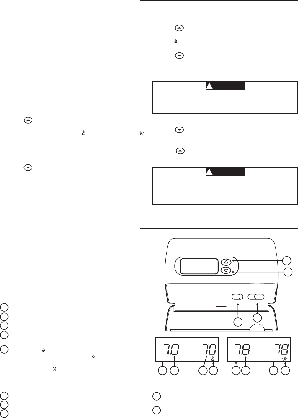
THERMOSTAT QUICK REFERENCE
2
1
34
5 810 6
958 7
Figure 5. Thermostat display, buttons, and switches
SU
MALFEMER
PM
SA
FLER
AM
FAN OFF HEAT
ON AUTO COOL EMER
Beforeyoubeginusingyourthermostat,youshouldbefamiliar
with its features and with the display and the location and op-
eration of the thermostat buttons. Your thermostat consists of
twoparts:thethermostat cover and the base. To remove the
cover, pull it straight out from the base. To replace the cover,
line up the cover with the base and press until the cover snaps
onto the base.
THE THERMOSTAT BUTTONS AND SWITCHES
(seeg.5)
1 Raises temperature setting.
2 Lowerstemperaturesetting.
3 FANswitch(ON, AUTO).
4 SYSTEMswitch(COOL, OFF, HEAT, EMER).
THE DISPLAY
5 Flame icon( )isdisplayedwhentheSYSTEMswitchis
intheHEATposition.Flame icon( )isdisplayedashing
when 2nd-stage heat (Aux or Emergency) is energized.
Snowflake icon( )isdisplayed(non-ashing)whenthe
SYSTEMswitchisintheCOOLposition.Snowflake and
Flame aredisplayed(ashing)ifthethermostatisinlockout
modetopreventthecompressorfromcyclingtooquickly.
6 Indicates a malfunction with the system.
7 Displays current temperature.
8 EMER is displayed flashing when the system switch is in
EMERposition.
9 Displayscurrentsettemperature(thisisblankwhenSYS-
TEMswitchisintheOFFposition).
10 Displays FILTER when the system has run for the programmed
filter time period as a reminder to change or clean.
1. MoveSYSTEMswitchtoEMERposition.EMERwillash
on the display.
2. Press to adjust the thermostat above room temperature.
The Aux heating system will begin to operate. The flame
icon( )willdisplayashingtoindicatethattheAuxsystem
is operating
3. Press to adjust the thermostat below room temperature.
The Aux heating system should stop operating.
5
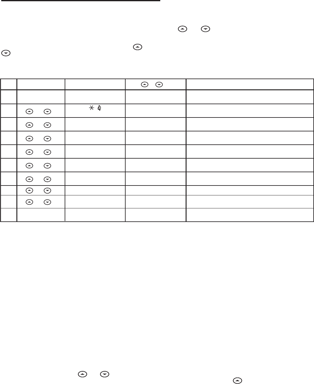
INSTALLER/CONFIGURATION MENU
1
Step Press or to select: COMMENTS
Displayed (Factory Default)Press Button(s)
2(SL) FA
5
6
7
8
LOC
(OFF) on
0HI
(0)
4LOto
4HI
(F) C
10
SelectCompressorlockoutOFForON
Selecttemperaturedisplay adjustment higher or lower
SelecttemperaturedisplaytoForC
4d-L
(on) OFF
Selectdisplay backlightOFForON
Filter
(000)
0to1950hours
(in50hourincrements)
Selectfilterreplacementrun time
SelectFAorSL(FastorSlow)pumpcyclerate
Configuration Menu
3EMER
(FA) SL SelectFAorSL(FastorSlow)Auxiliary and
EmergencyAux heating cycle rate
and
and
and
9FA
(on) OFF
Selectfastsecond-stageONorOFF
and
and
and
and
and
SetSYSTEM
switchtoOFF
SYSTEMswitchmustbeOFFtoconfigurethermostat options
SetSYSTEMswitch
toHEATorCOOL
Returns to normal operation
* Press and
to advance to next item
CONFIGURATION MENU
The configuration menu allows you to set certain thermostat
operating characteristics to your system or personal require-
ments.
MoveSYSTEMswitchtotheOFFposition,thenpress and
at the same time to enter the configuration menu. The
display will show the first item in the configuration menu.
The configuration menu chart summarizes the configuration
options. An explanation of each option follows.
Press and to change to the next menu item. To exit
themenu,movetheSYSTEMswitchtoHEATorCOOL.Ifno
keysarepressedwithinfteenminutes,thethermostatwillexit
the configuration menu.
2) Select FA or SL (Fast or Slow) Heat Pump stage Cycle
Rate-TheFAsettingisusedtoproduceshorterheatingcycles.
TheSLsettingproducesalongerheating/coolingcycle.Both
settings produce very accurate temperature control and can be
settoyourpersonalpreference.FAcyclesthesystemjustunder
.75°FandtheSLsettingcyclesatapproximately1.2°F.
3) Select FA or SL (Fast or Slow) Auxiliary or Emergency Cycle
Rate-TheFAsettingisfrequentlyusedforgas,oilorelectric
heat.TheSLsettingproducesalongerheatingcycle.Bothset-
tings produce very accurate temperature control and can be set
toyourpersonalpreference.FAcyclesthesystemjustunder
.6°FandtheSLsettingcyclesatapproximately1.°F.
4) Select backlit display (d-L OFF or ON) - The display
backlightimprovesdisplaycontrastinlowlightingconditions.
SelectingbacklightONwillkeepthelightoncontinuously.
SelectingOFFwillkeepthelightoff.
5) Select filter replacement run time - The thermostat will
display FILTER after a set time of operation. This is a re-
minder to change or clean your air filter. This time can be
setfrom0to1950hoursin50hourincrements.A selection
of 000 will cancel this feature. When FLTR is displayed,
you can clear it by pressing and at the same time.
This resets the timer and starts counting the hours until the
nextlterchange.Contactyourheatpumpmanufacturerfor
aspecicreplacement/maintenanceinterval.
6) Select Compressor Lockout (LOC OFF or ON)-Selecting
LOCONwillcausethethermostattowait5minutesbefore
turning on the compressor if the heating and cooling system
losespower.Itwillalsowait5minutesminimumbetweencool-
ing cycles. This is intended to help protect the compressor from
shortcycling.Somenewercompressorsalreadyhaveatime
delay built in and do not require this feature. Your compressor
manufacturer can tell you if the feature is already present in
their system. When the thermostat compressor time delay
occurs it will flash the Snowflake or Flame icon for about
five minutes.
7) Select Temperature Display Adjustment (4 LO to 4 HI) -
Allowsyoutoadjusttheroomtemperaturedisplayupto4°
higher or lower. Your thermostat was accurately calibrated
at the factory but you have the option to change the display
temperature to match your previous thermostat. The current
or adjusted room temperature will be displayed on the right
side of the display.
8) Select Temperature Display (°F or °C) -Changesthedisplay
readouttoCelsiusorFahrenheitasrequired.Thecurrent
room temperature will be displayed on the right side of the
display.
9) Select Fast second stage - IntheRUNmode,ifthetem-
perature is manually raised by 3°F (2°C) or more above
room temperature using and the fast second stage
featureisenabled,FAon,thesecondstagewillenergize
immediately.WithFAoff,thesecondstagewillnotenergize
untilthesetpointtemperatureis10°Formoreaboveroom
temperature.
6
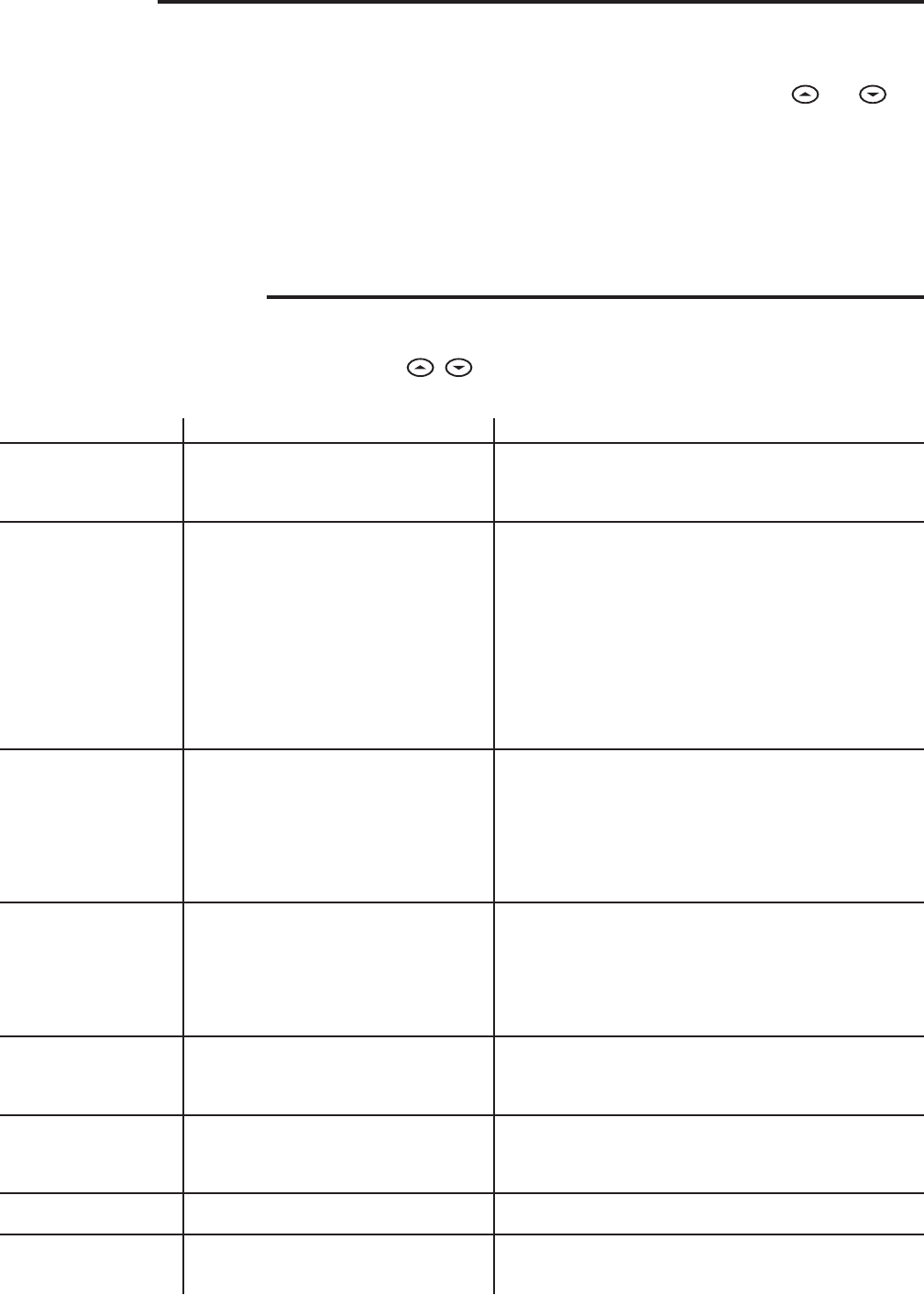
TROUBLESHOOTING
Reset Operation
Ifavoltagespikeorstaticdischargeblanksoutthedisplayorcauseserraticthermostatoperationyoucanresetthethermostat
bychangingthesystemfromOfftoHeatwhilepressing , at the same time. If the thermostat has power, has been reset
andstilldoesnotfunctioncorrectlycontactyourheating/coolingservicepersonorplaceofpurchase.
Symptom Possible Cause Corrective Action
No Heat/No Cool/No Fan
(common problems)
1. Blownfuseortrippedcircuitbreaker.
2. FurnacepowerswitchtoOFF.
3. Furnaceblowercompartmentdoororpanel
loose or not properly installed.
Replacefuseorresetbreaker.
TurnswitchtoON.
Replacedoorpanelinproperpositiontoengagesafetyinterlockor
door switch.
No Heat 1. SystemSwitchnotsettoHeat.
2. Looseconnectiontothermostatorsystem.
3. HeatingSystemrequiresserviceor
thermostat requires replacement.
SetSystemSwitchtoHeatandraisesetpointaboveroom
temperature.
Verifythermostatandsystemwiresaresecurelyattached.
Diagnostic:SetSystemSwitchtoHeatandraisethesetpoint
above room temperature. Within five minutes the thermostat
shouldmakeasoftclicksound.Thissoundusuallyindicatesthe
thermostatisoperatingproperly.Ifthethermostatdoesnotclick,
trytheresetoperationlistedabove.Ifthethermostatdoesnotclick
after being reset contact your heating and cooling service person
orplaceofpurchaseforareplacement.Ifthethermostatclicks,
contact the furnace manufacturer or a service person to verify the
heating system is operating properly.
No Cool 1. SystemSwitchnotsettoCool.
2. Looseconnectiontothermostatorsystem.
3. CoolingSystemrequiresserviceor
thermostat requires replacement.
SetSystemSwitchtoCoolandlowersetpointbelowroom
temperature.
Verifythermostatandsystemwiresaresecurelyattached.
SameprocedureasdiagnosticforNoHeatconditionexceptset
thethermostattoCoolandlowerthesetpointbelowtheroom
temperature. There may be up to a five minute delay before the
thermostatclicksinCoolingifthecompressorlock-outoptionis
selectedinthecongurationmenu(Item6).
Heat, Cool or Fan
Runs Constantly
1. Possibleshortinwiring.
2. Possibleshortinthermostat.
3. PossibleshortinHeat/Cool/Fansystem.
4. FanSwitchsettoFanOn.
Checkeachwireconnectiontoverifytheyarenotshortedor
touchingtogether.Nobarewireshouldstickoutfromunder
terminal screws. Try resetting the thermostat as described above. If
the condition persists, the manufacturer of your system or service
personcaninstructyouonhowtotesttheHeat/Coolsystemfor
correct operation. If the system operates correctly, replace the
thermostat.
Furnace Cycles Too Fast
or Too Slow
(narrow or wide
temperature swing)
1. Thelocationofthethermostatand/or
thesizeoftheHeatingSystemmaybe
influencing the cycle rate.
Item2intheCongurationMenuistheadjustmentthatcontrols
the cycle rate. If an acceptable cycle rate is not achieved using the
FA(Fast)orSL(Slow)adjustmentcontactalocalserviceperson
for additional suggestions.
Cooling Cycles Too
Fast or Too Slow
(narrow or wide
temperature swing)
1. Thelocationofthethermostatand/or
thesizeoftheCoolingSystemmaybe
influencing the cycle rate.
Thecyclerateforcoolingisxedandcannotbeadjusted.Contact
a local service person for suggestions.
Thermostat Setting and
Thermometer Disagree
1. Thermostat thermometer setting requires
adjustment.
Thethermometercanbeadjusted+/-4degreesaslistedinitem7
oftheCongurationMenu.Nootheradjustmentispossible.
Blank Display and/or
Keypad Not Responding
1. Lossofpower.
2. VoltageSpikeorStaticDischarge.
Checkheat/coolsystemforpower.
IfavoltagespikeorstaticdischargeoccursusetheReset
Operationlistedabove.
OPERATING FEATURES
Nowthatyouarefamiliarwiththethermostatbuttonsanddisplay,
read the following information to learn about the many features
of the thermostat.
• SIMULTANEOUS HEATING/COOLING SETPOINT STOR-
AGE — You can enter both your heating and cooling set-
points at the same time. There is no need to change the
thermostat at the beginning of each season.
• CONFIGURATION MENU — Allows you to customize
certain thermostat options.
OPERATION
SETTING THE THERMOSTAT
This thermostat is very easy to operate. Set the SYSTEM
switchtoeitherHEATorCOOLthenpress and until
the temperature you want to maintain is shown on the right side
of the display. If you want to turn the system off, just move the
SYSTEMswitchtoOFF.
The FAN switch controls the fan operation. When the FAN
switchissettoAUTO,thefanwillcyclewiththefurnaceorair
conditioner.WhentheFANswitchissettoON,thefanwillrun
continuously,regardlessofSYSTEMswitchposition.

7
NOTES

HOMEOWNER HELP LINE: 1-800-284-2925
White-Rodgers is a business
ofEmersonElectricCo.
TheEmersonlogoisa
trademarkandservicemark
ofEmersonElectricCo.
www.white-rodgers.com
www.emersonclimate.com
