Wi Lan EB03 DSSS data Transceiver for LAN or WAN User Manual 120 24
Wi Lan Inc DSSS data Transceiver for LAN or WAN 120 24
UserManual.wiki
>
Wi Lan
>
EB03 User Manual
Users Manual
Navigation menu
Upload a User Manual
Namespaces
Wiki Guide
HTML
PDF
Info
Views
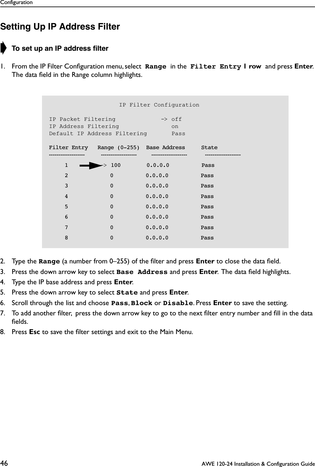
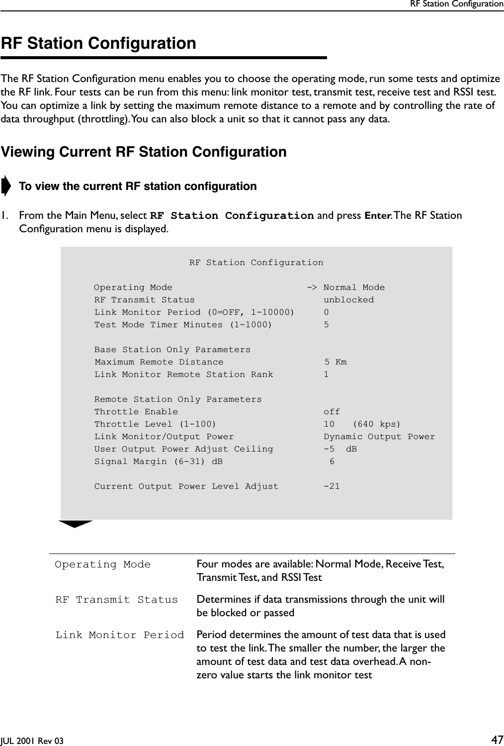
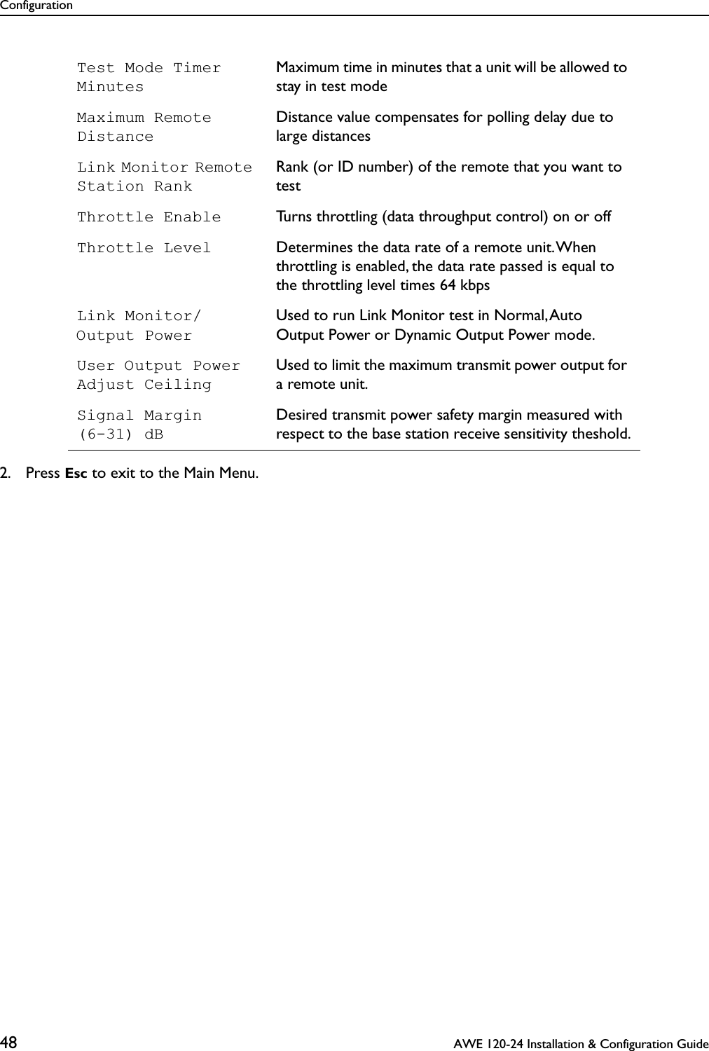
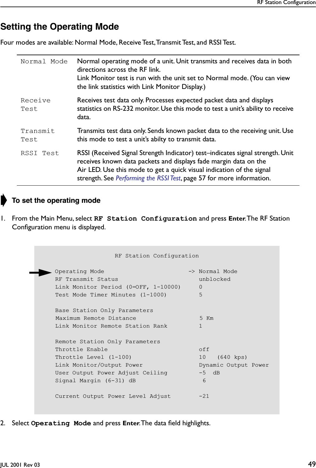
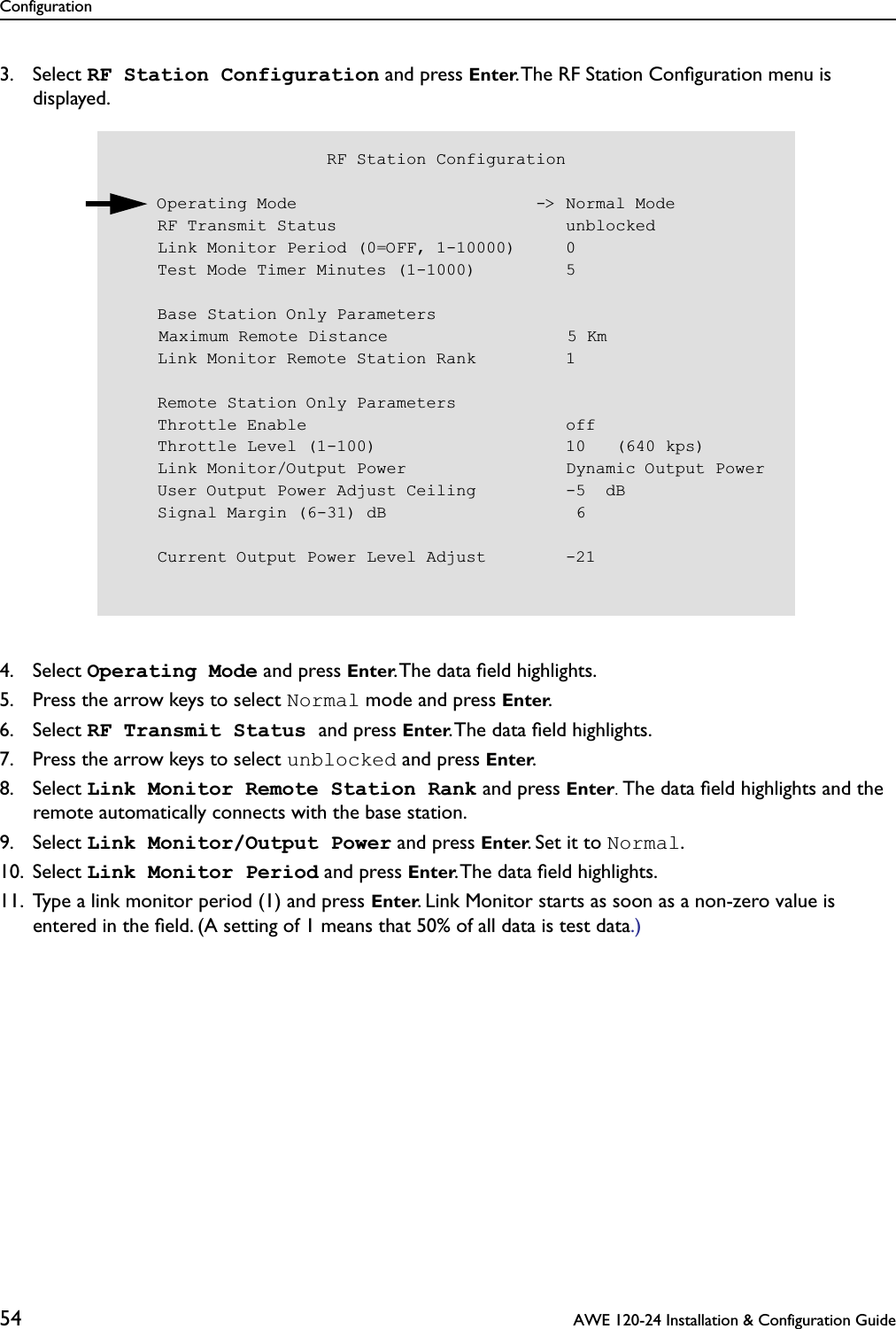
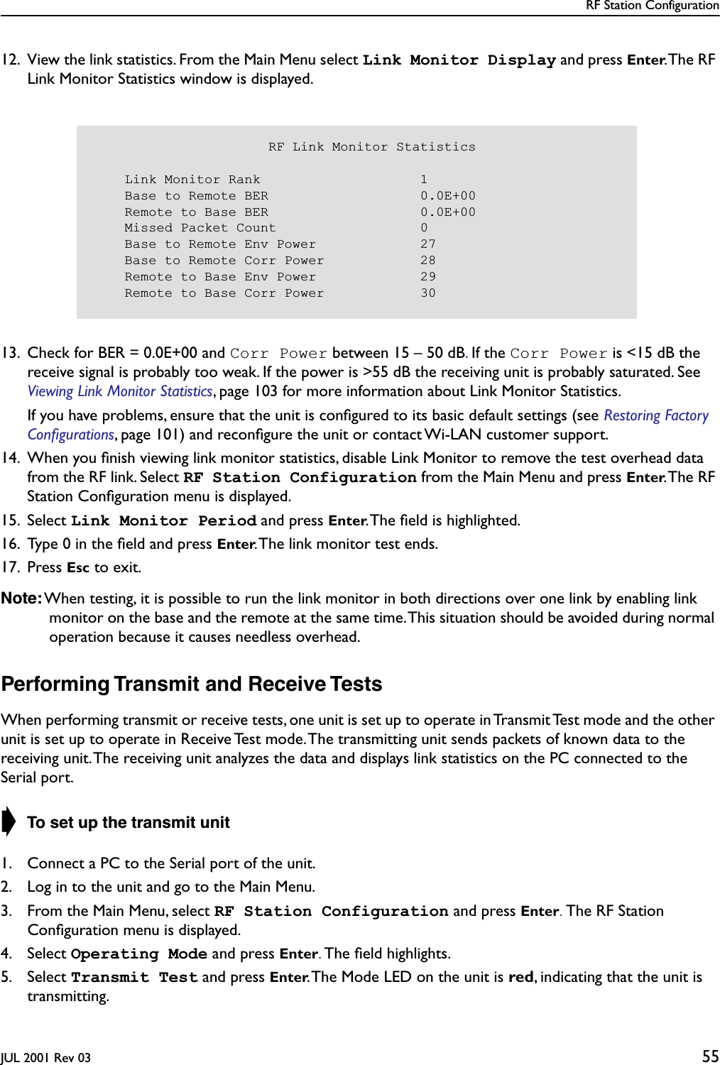
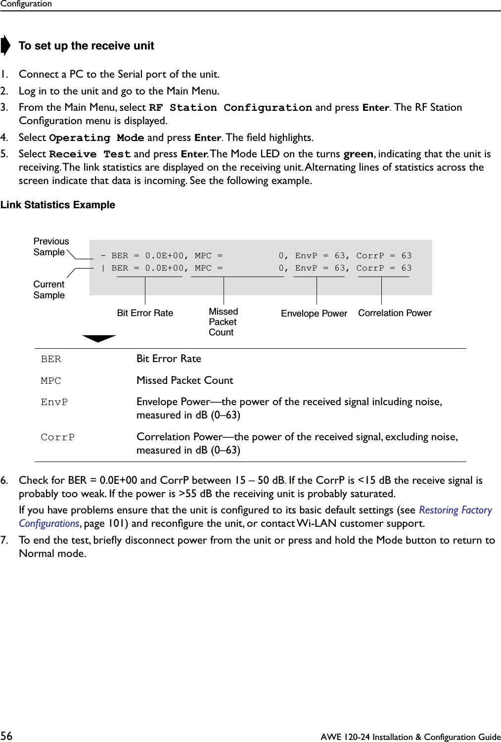
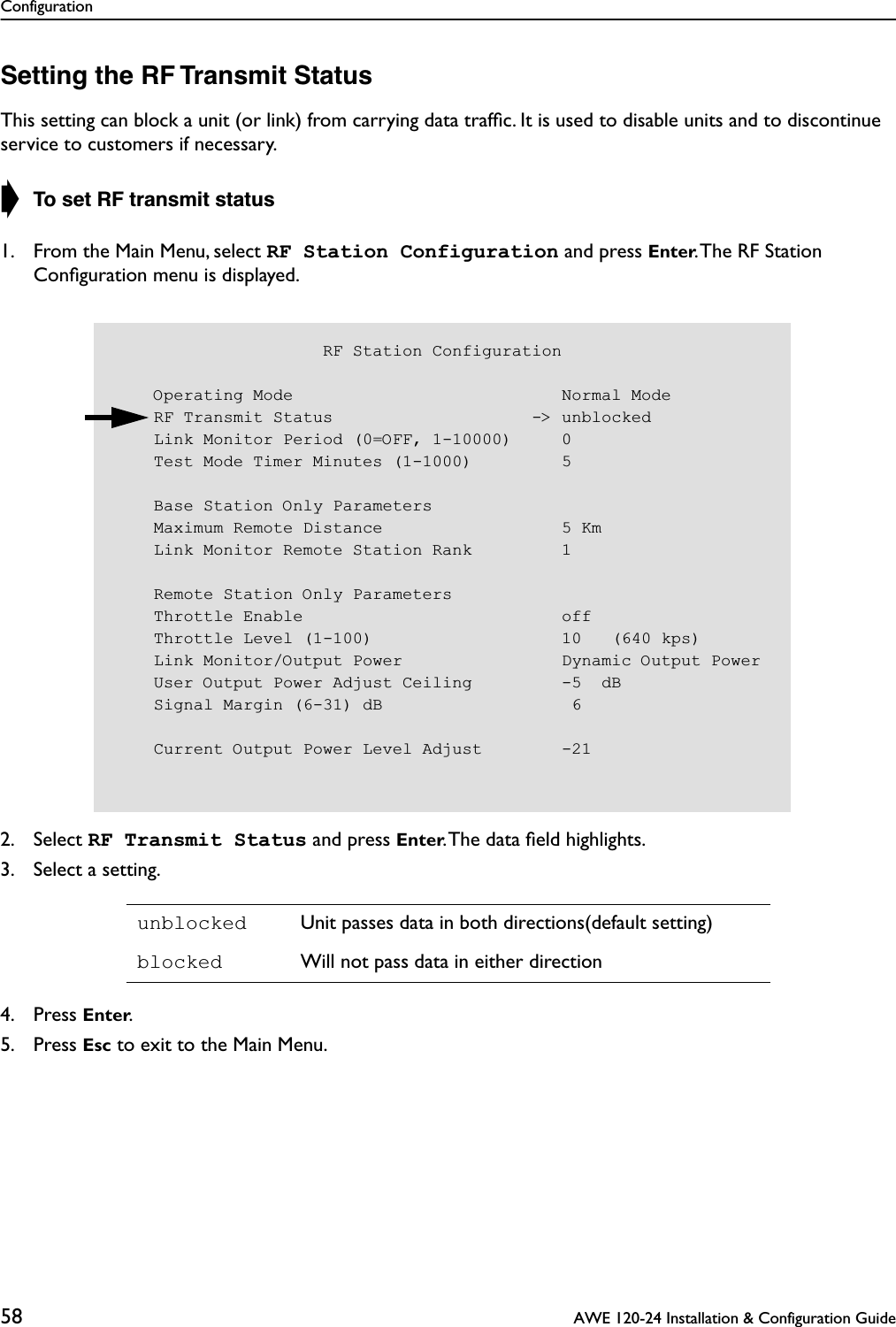
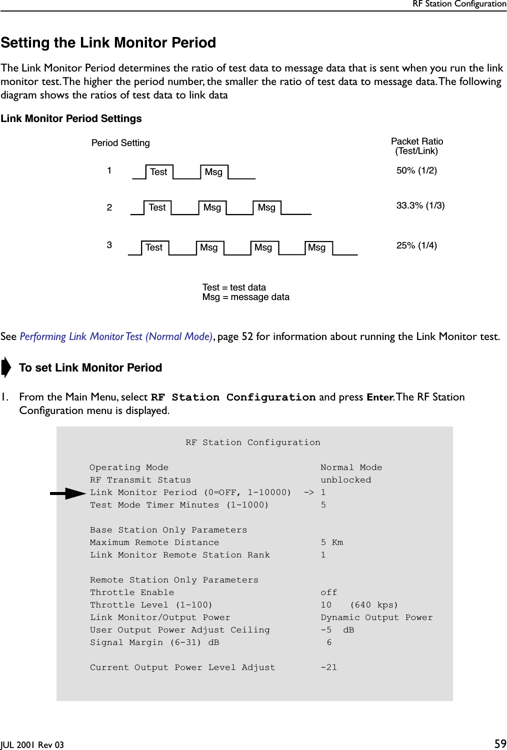
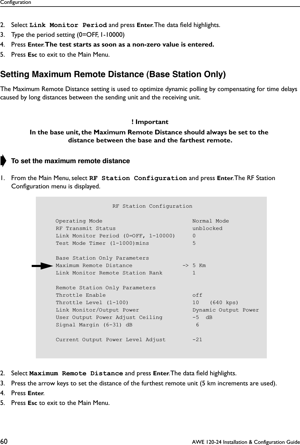
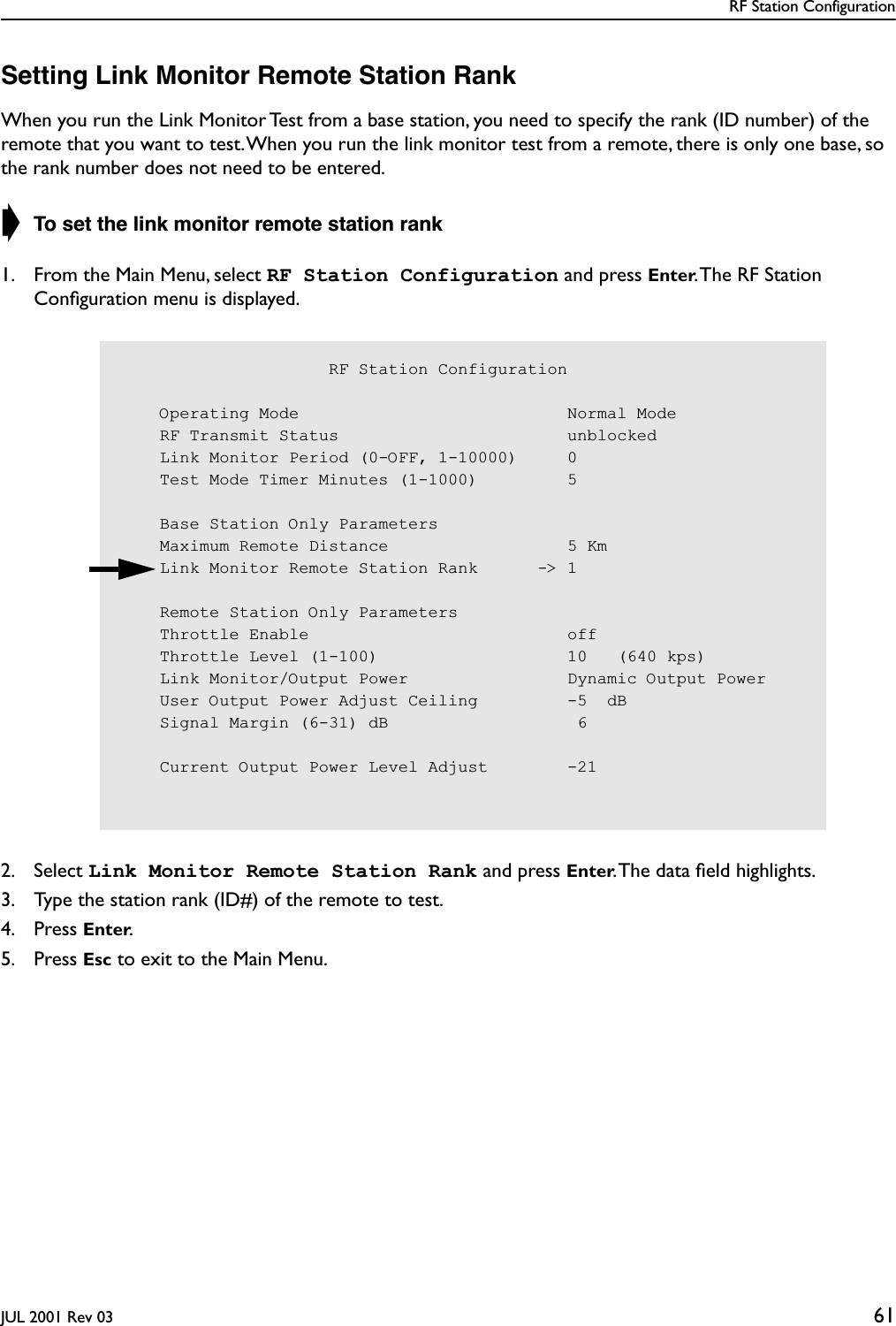
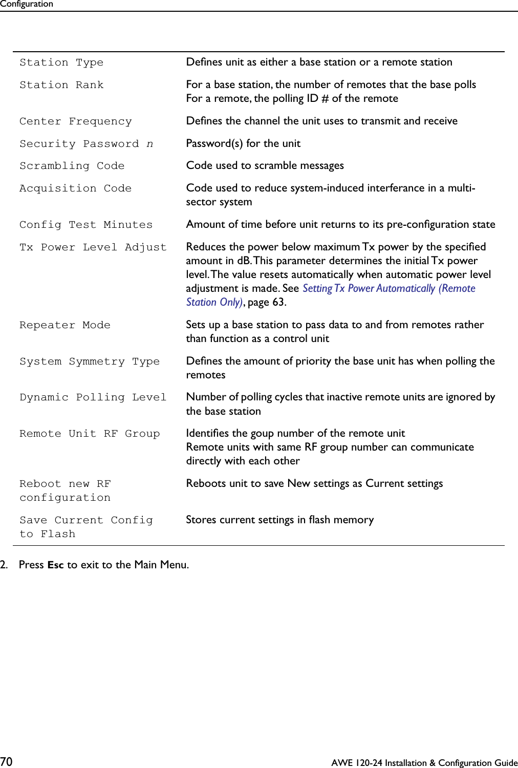
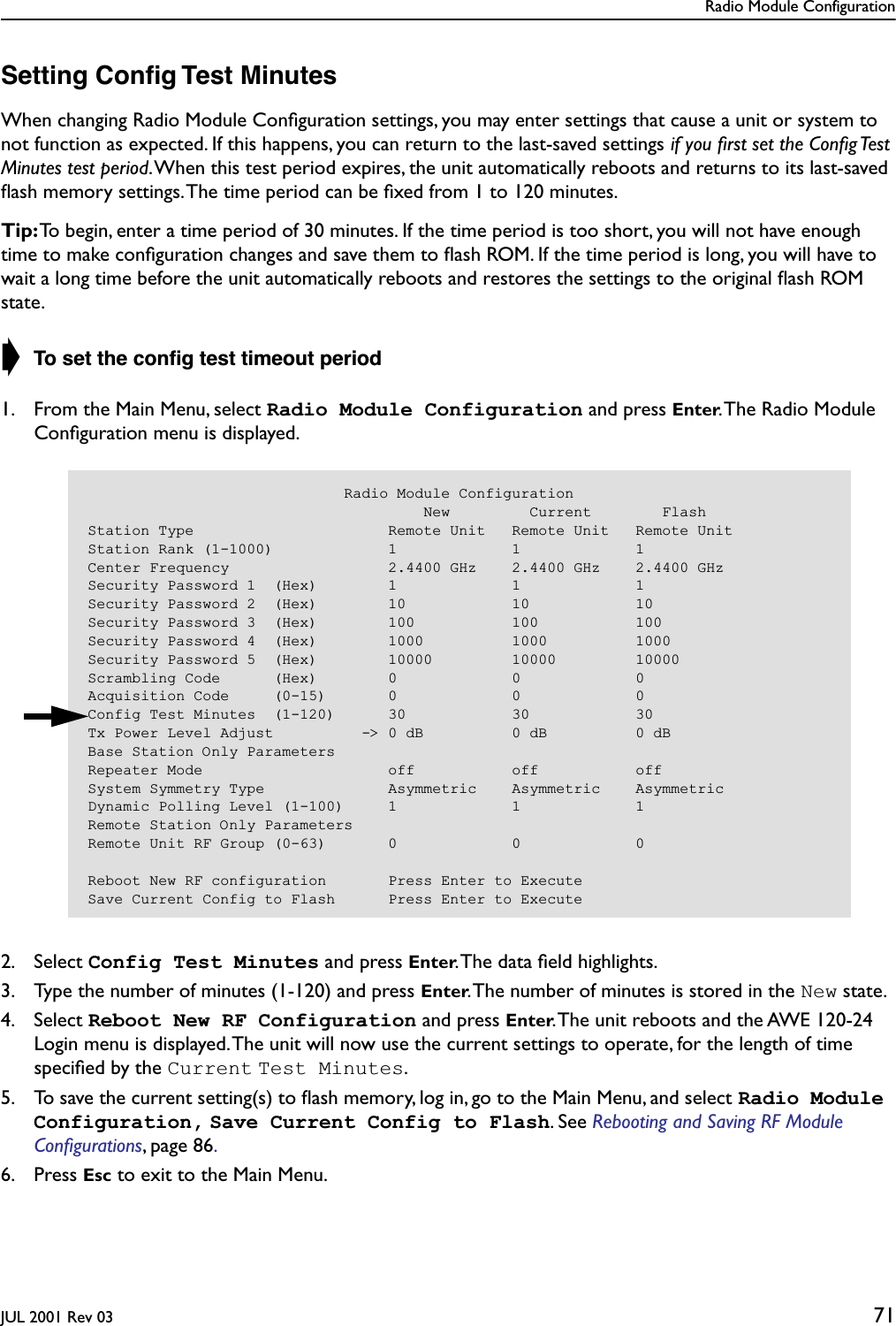
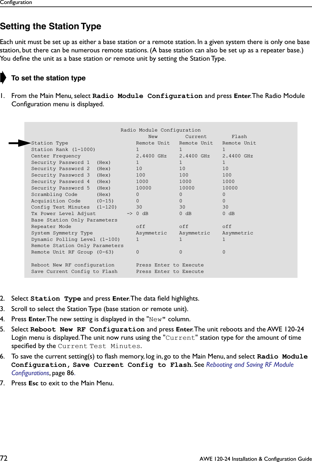
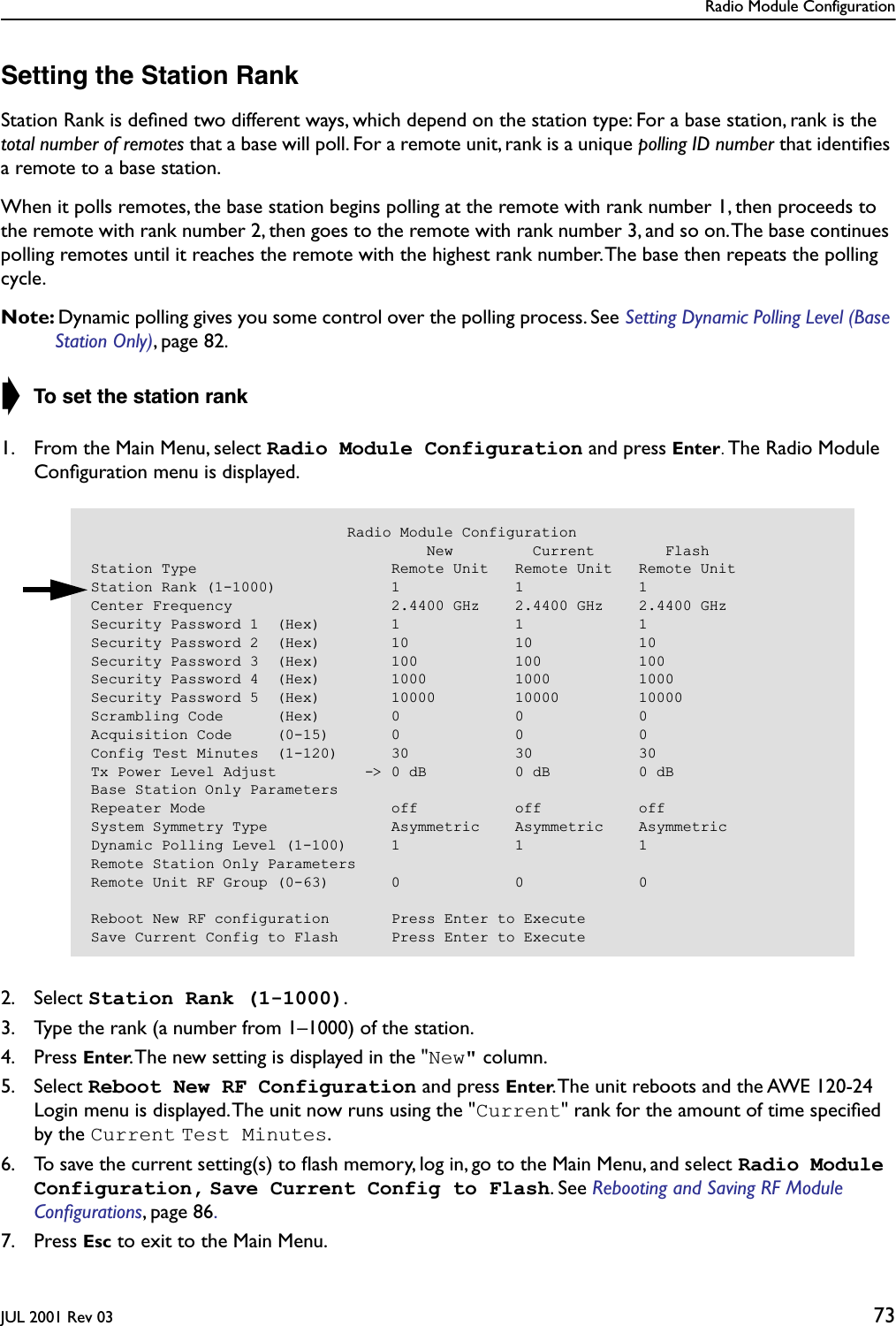
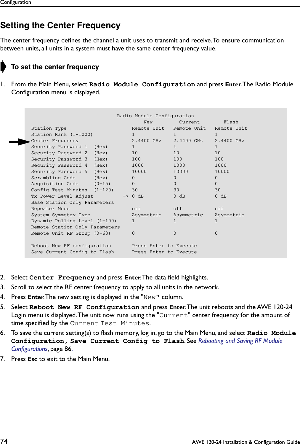
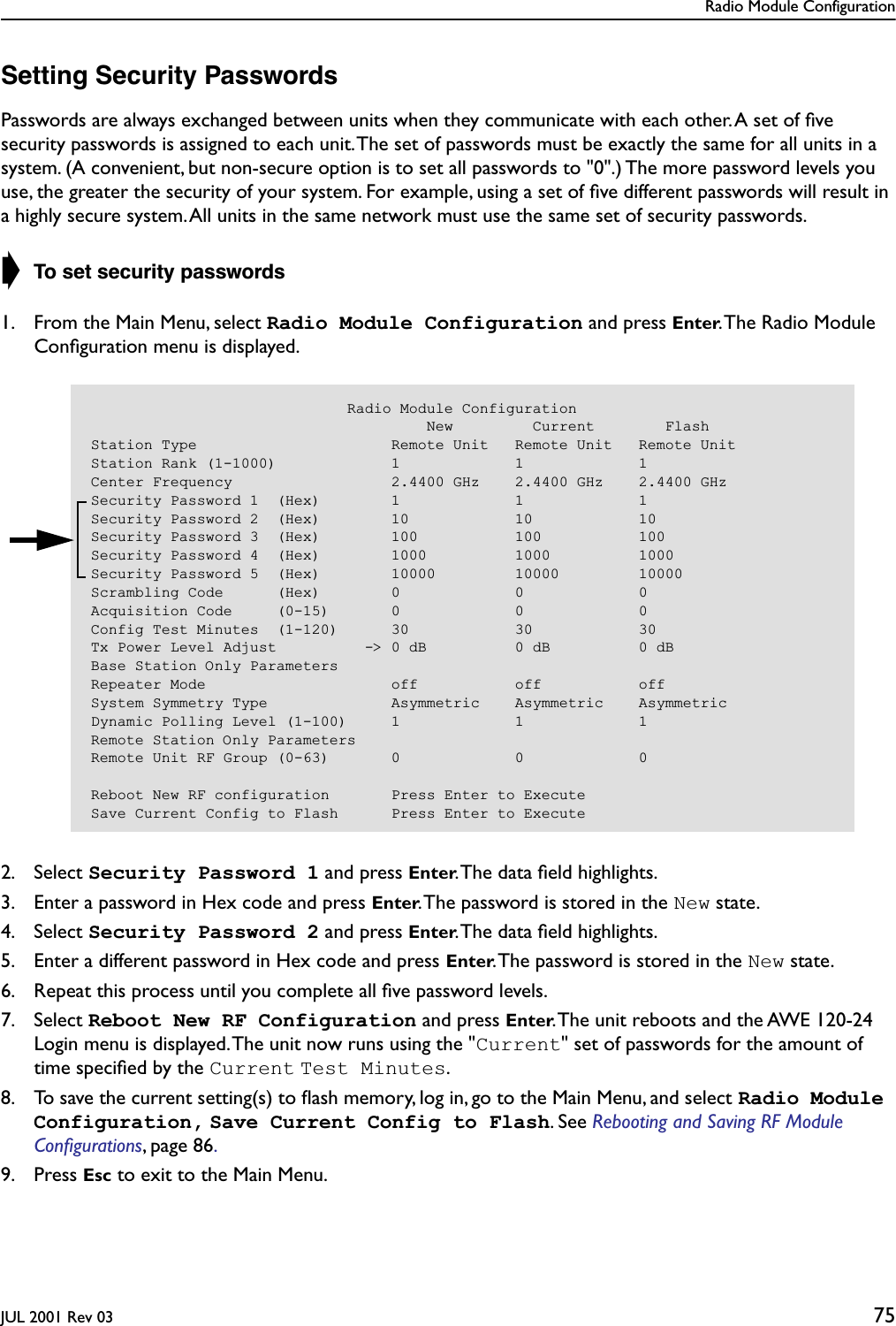
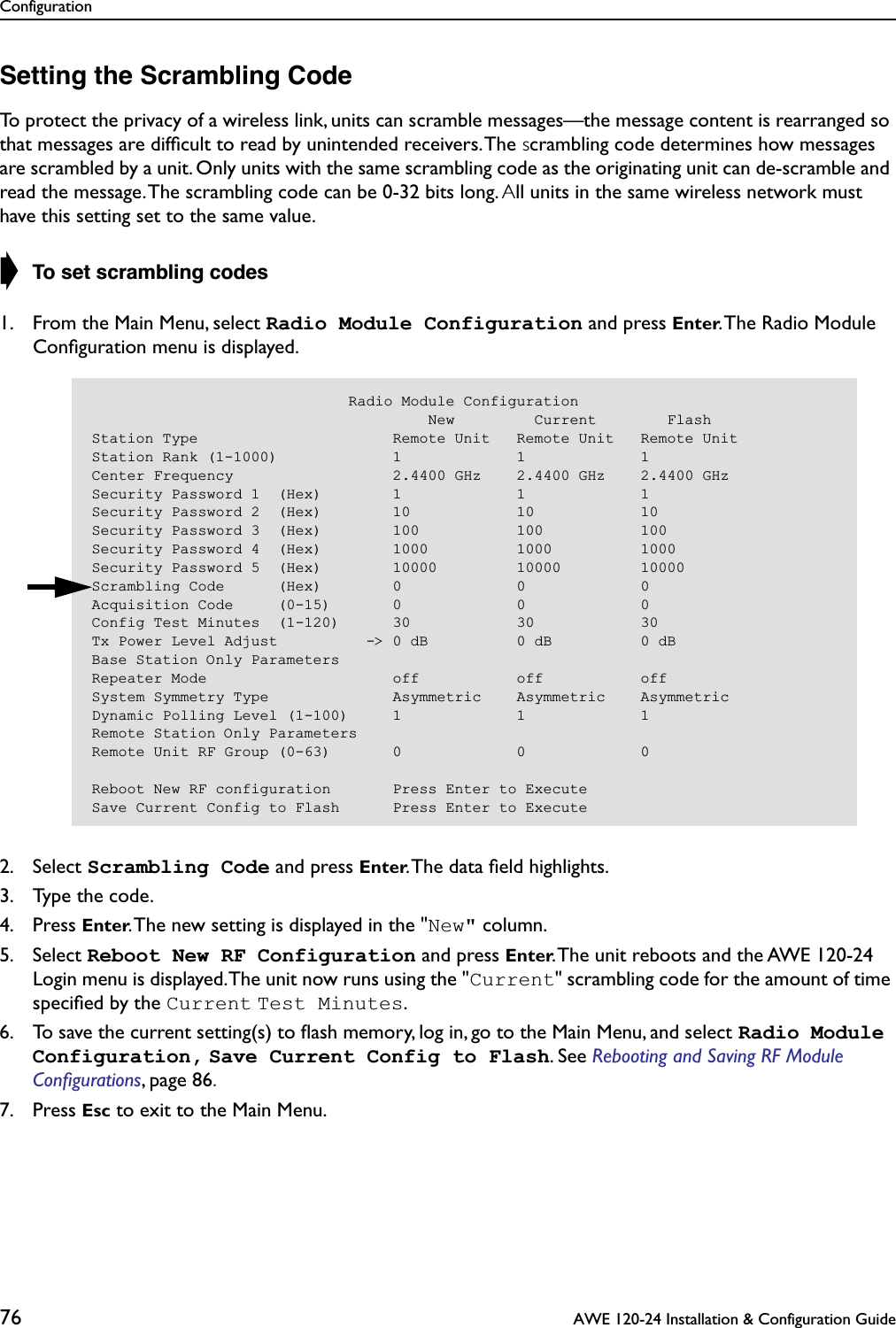
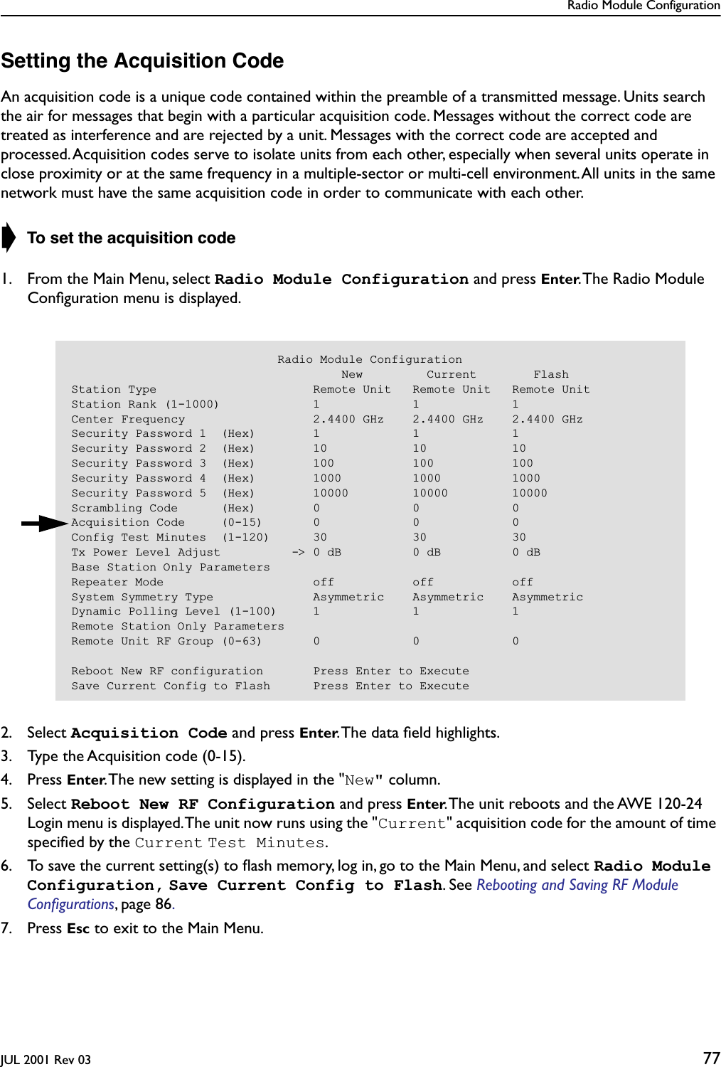
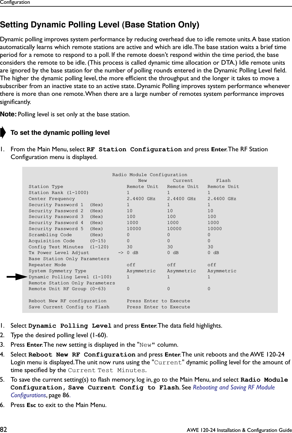
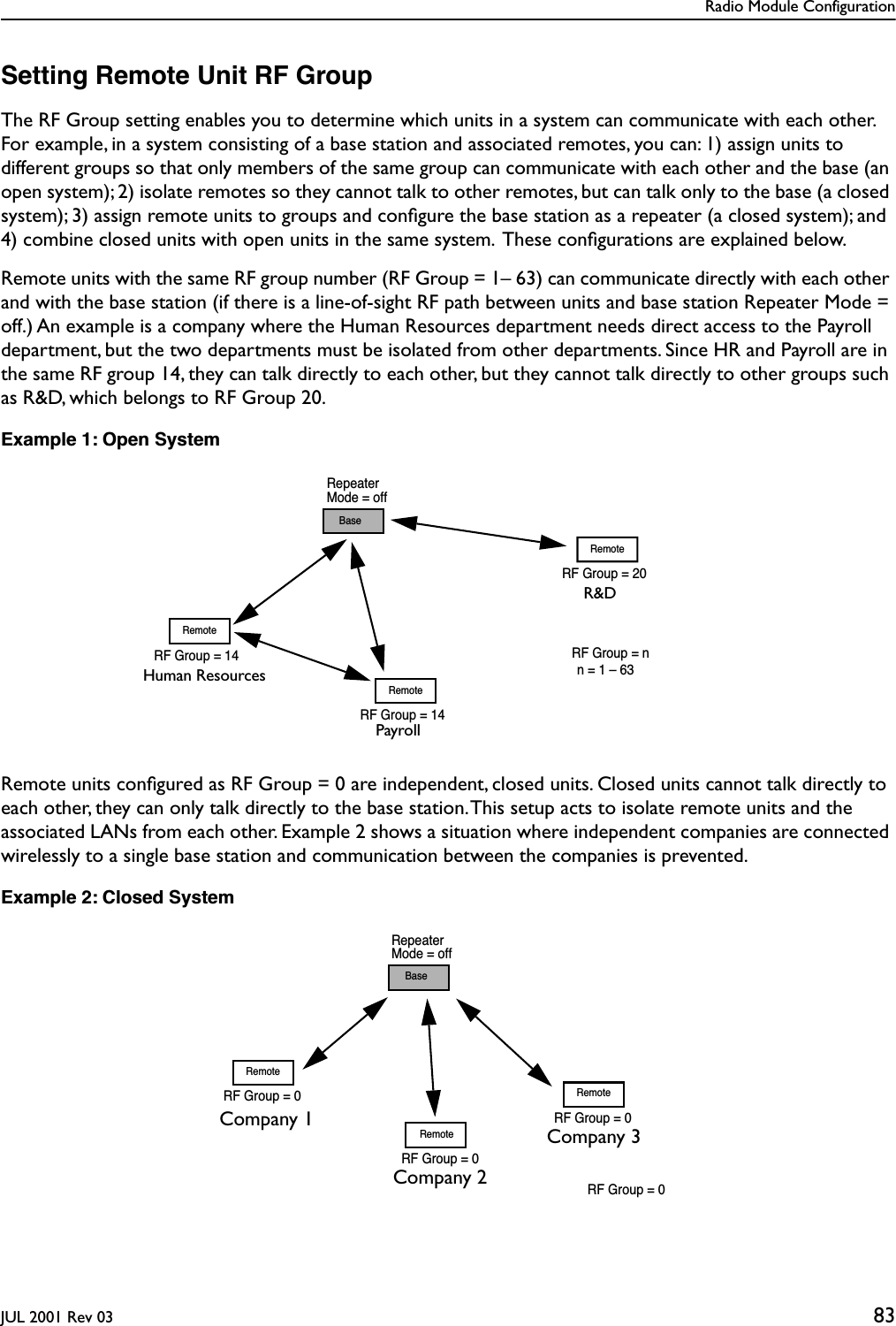
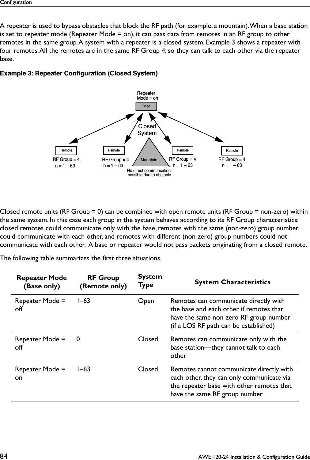
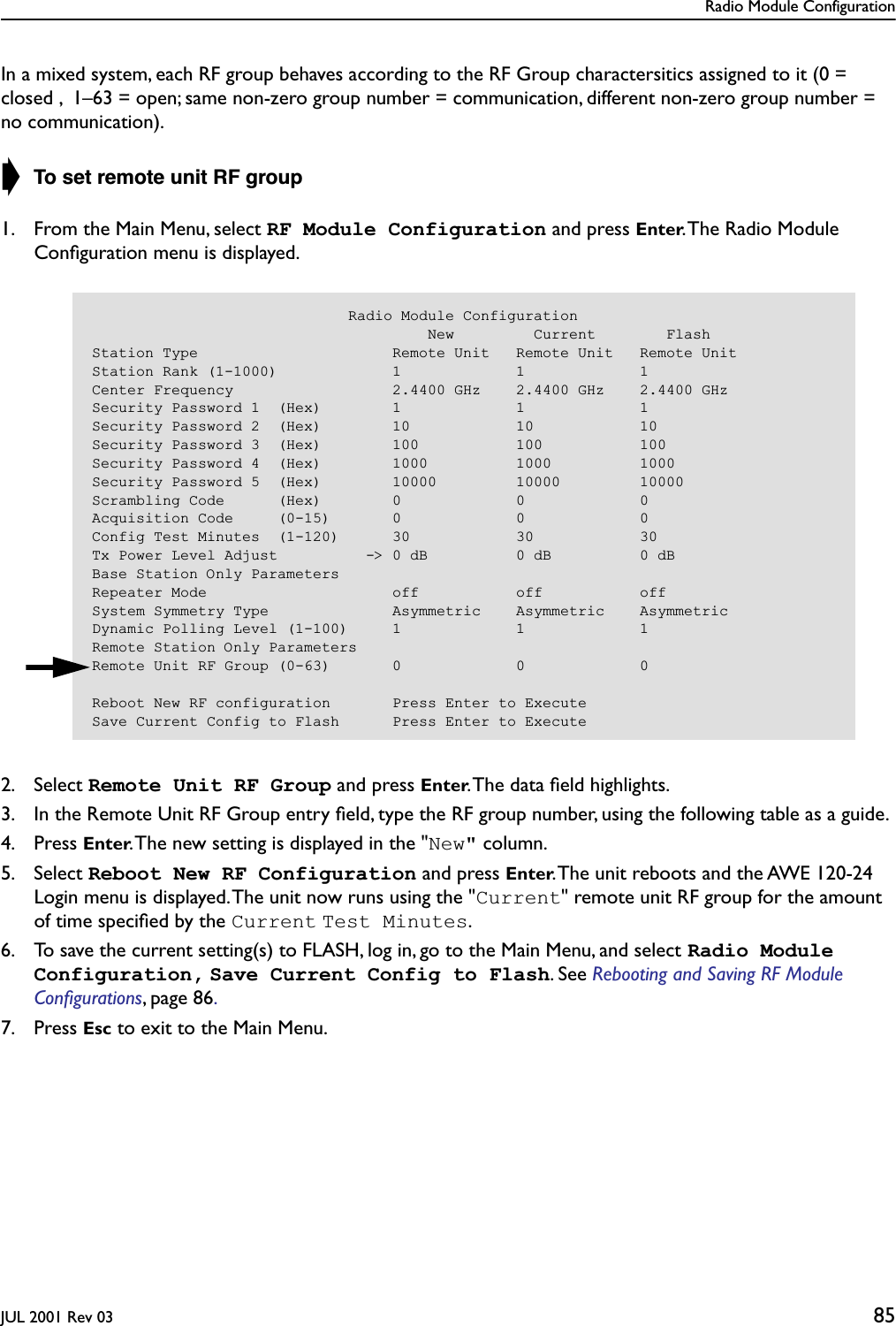
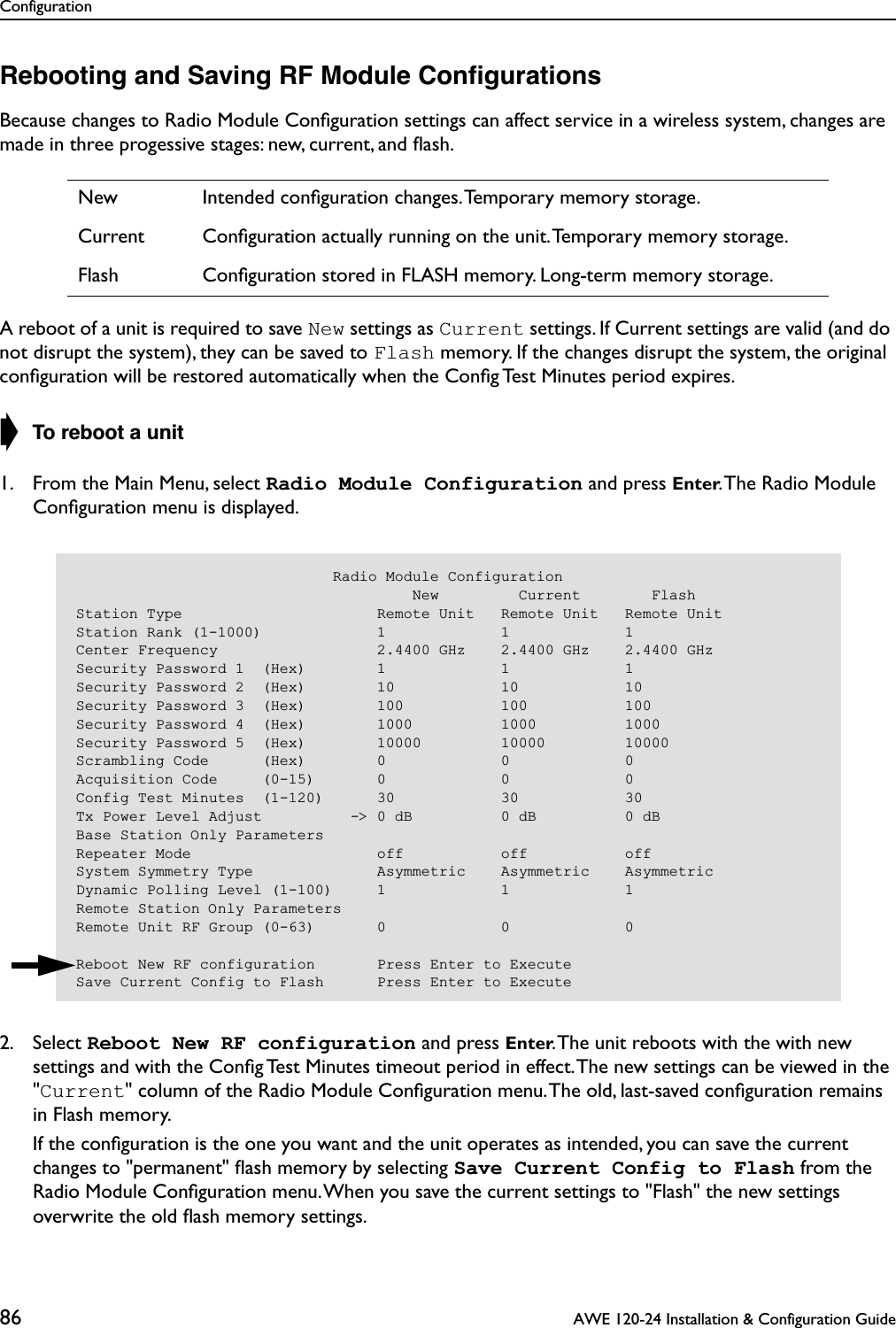
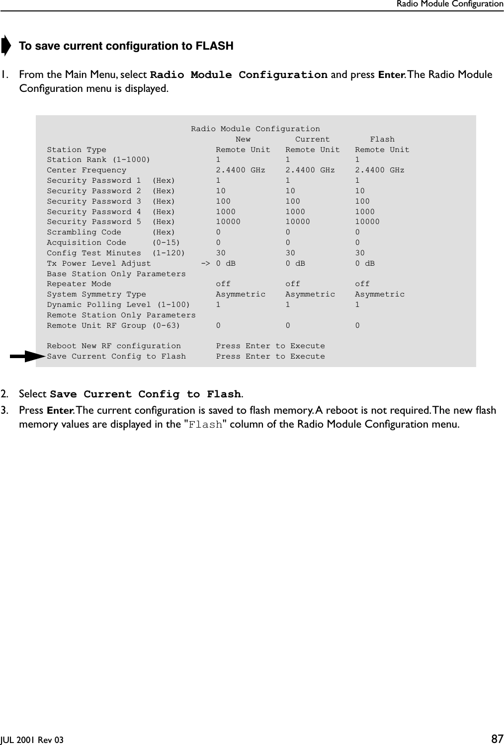
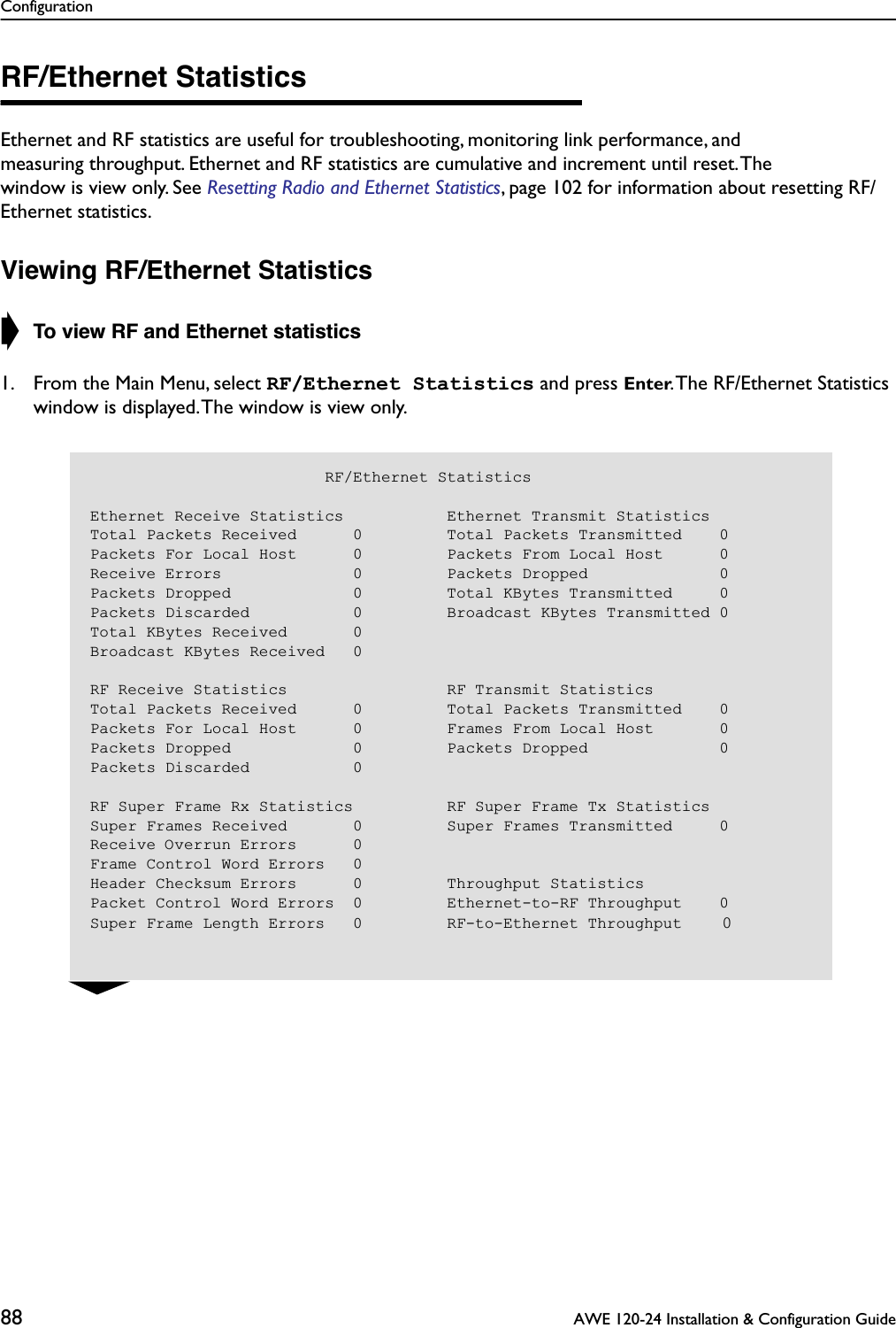
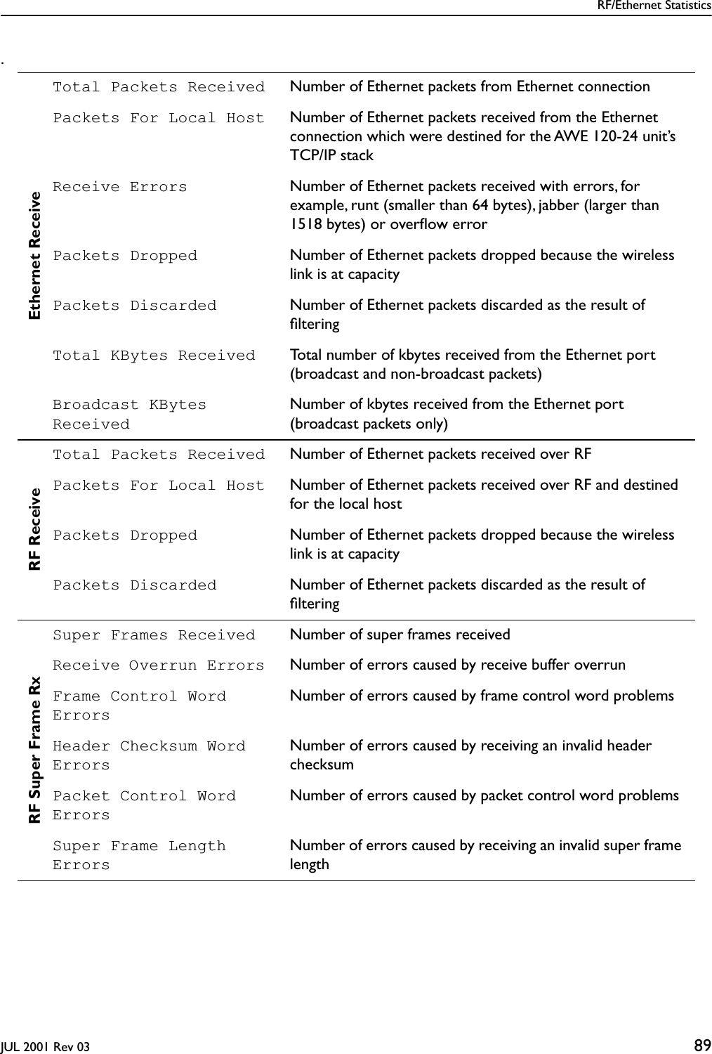
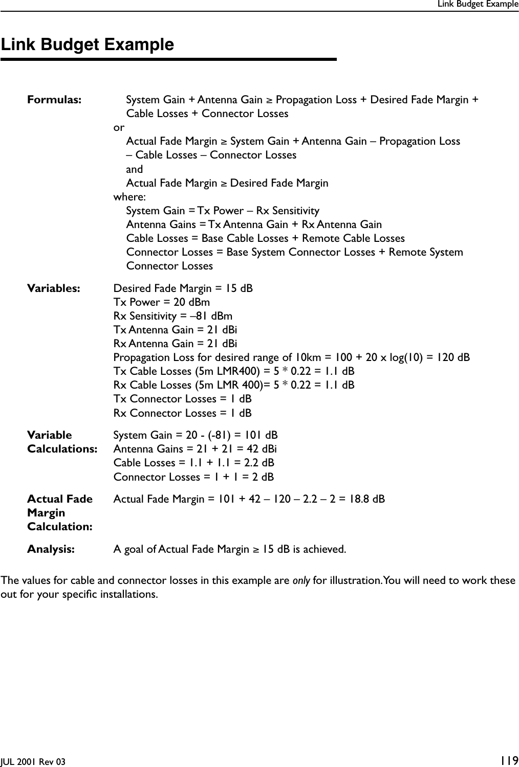
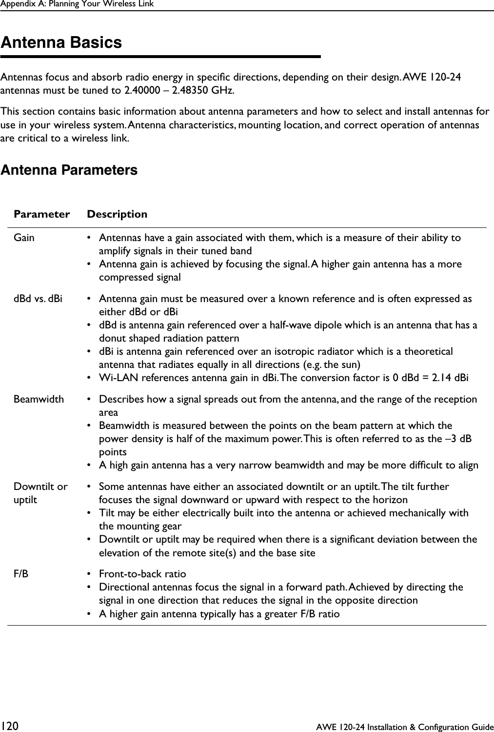
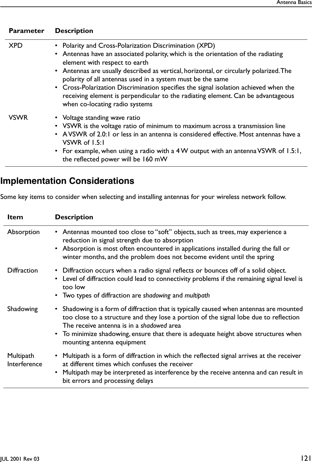
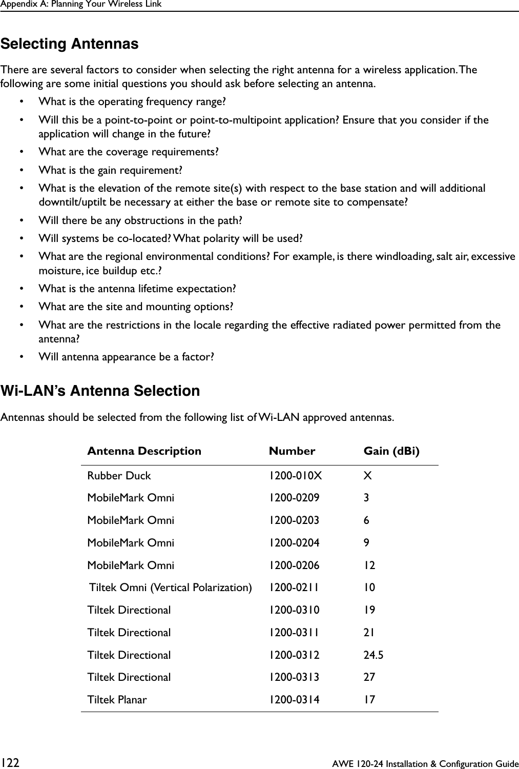
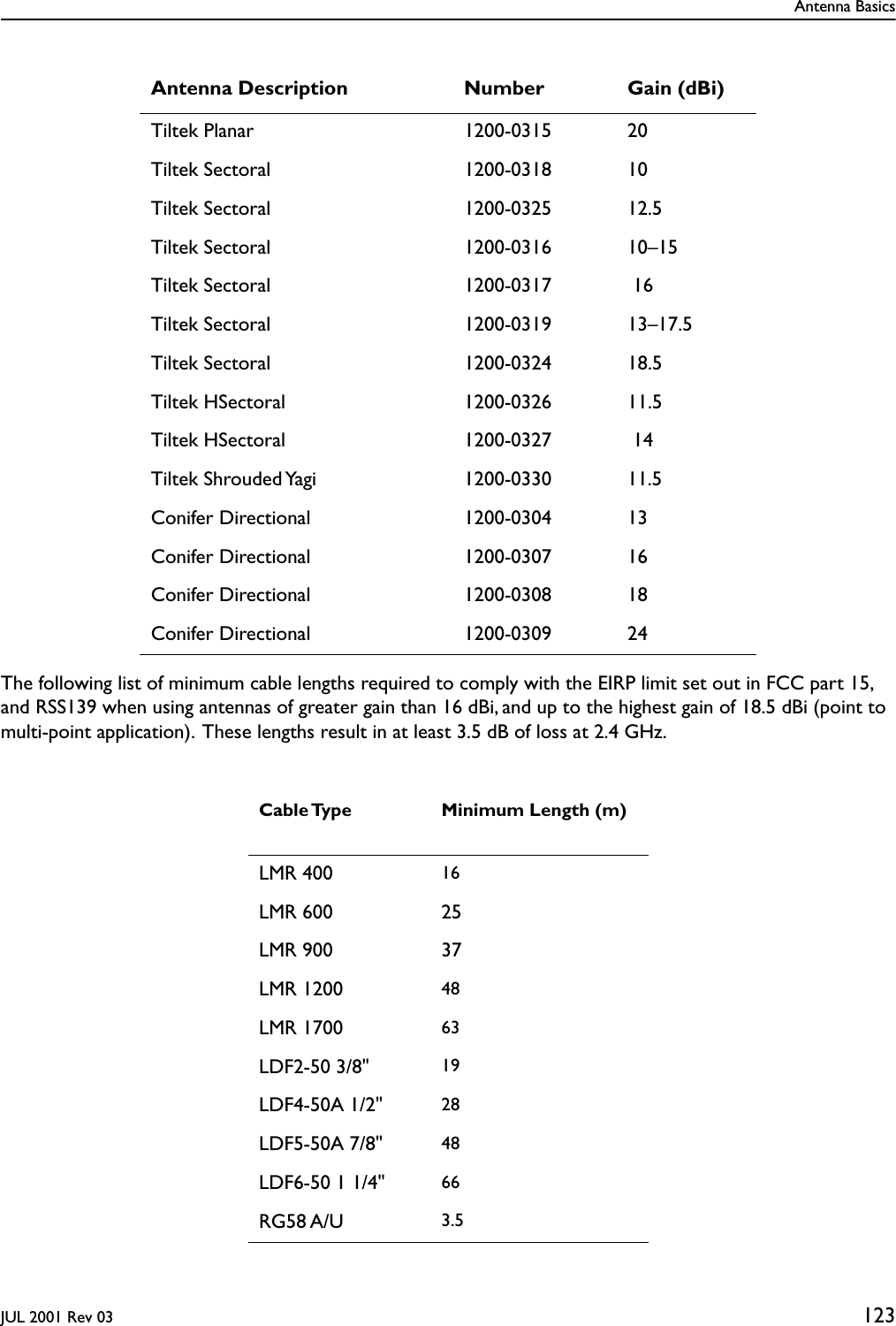
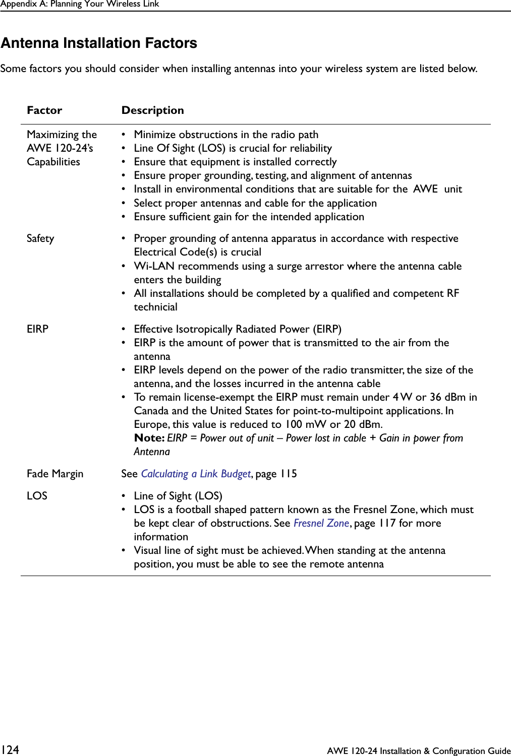
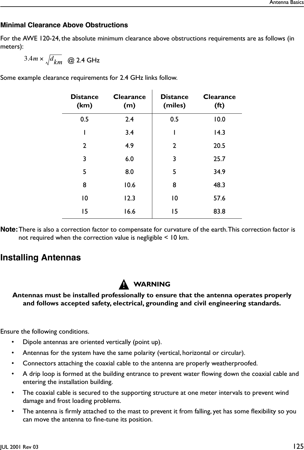
User Manual
Discussion / Help
Navigation