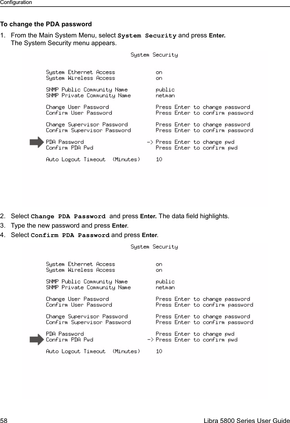
Wi Lan EB05 Wireless Network Transmitter User Manual Libra 5800
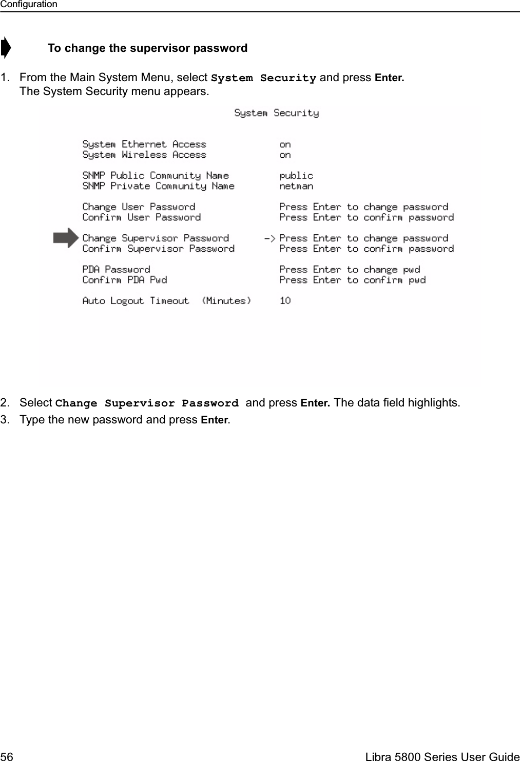
Wi Lan Inc Wireless Network Transmitter Libra 5800
UserManual.wiki
>
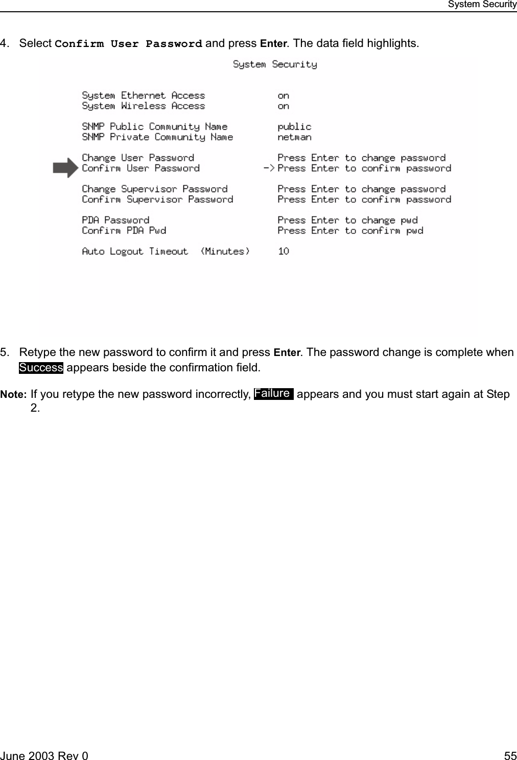
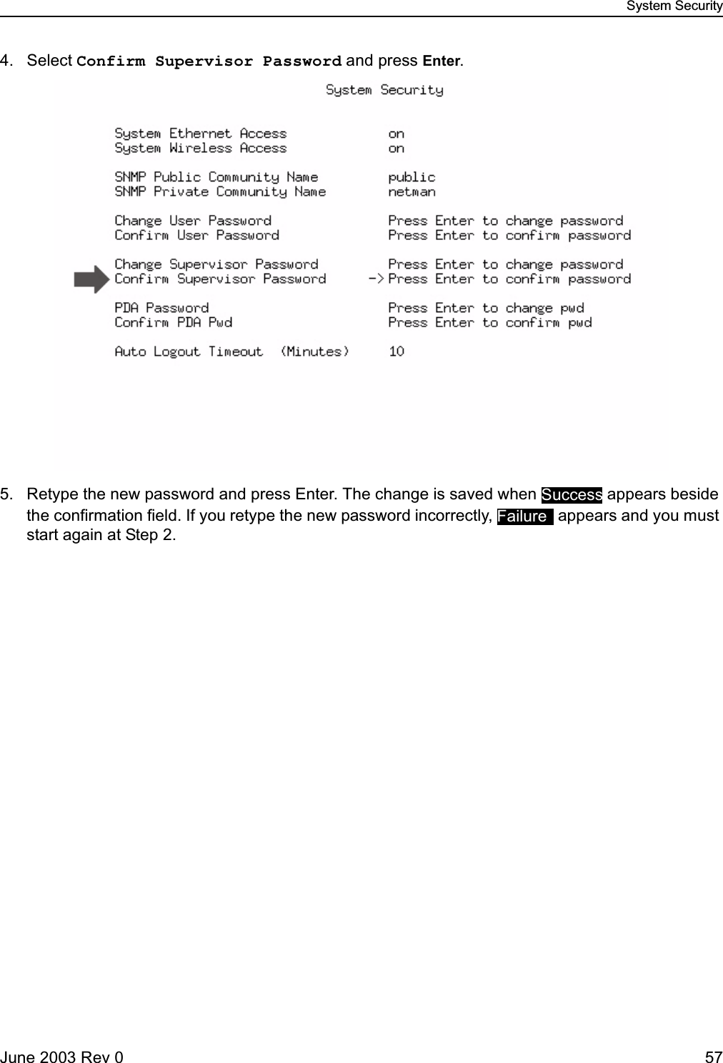
Wi Lan
>
EB05 User Manual
Users Manual
Navigation menu
Upload a User Manual
Namespaces
Wiki Guide
HTML
PDF
Info
Views
User Manual
Discussion / Help
Navigation
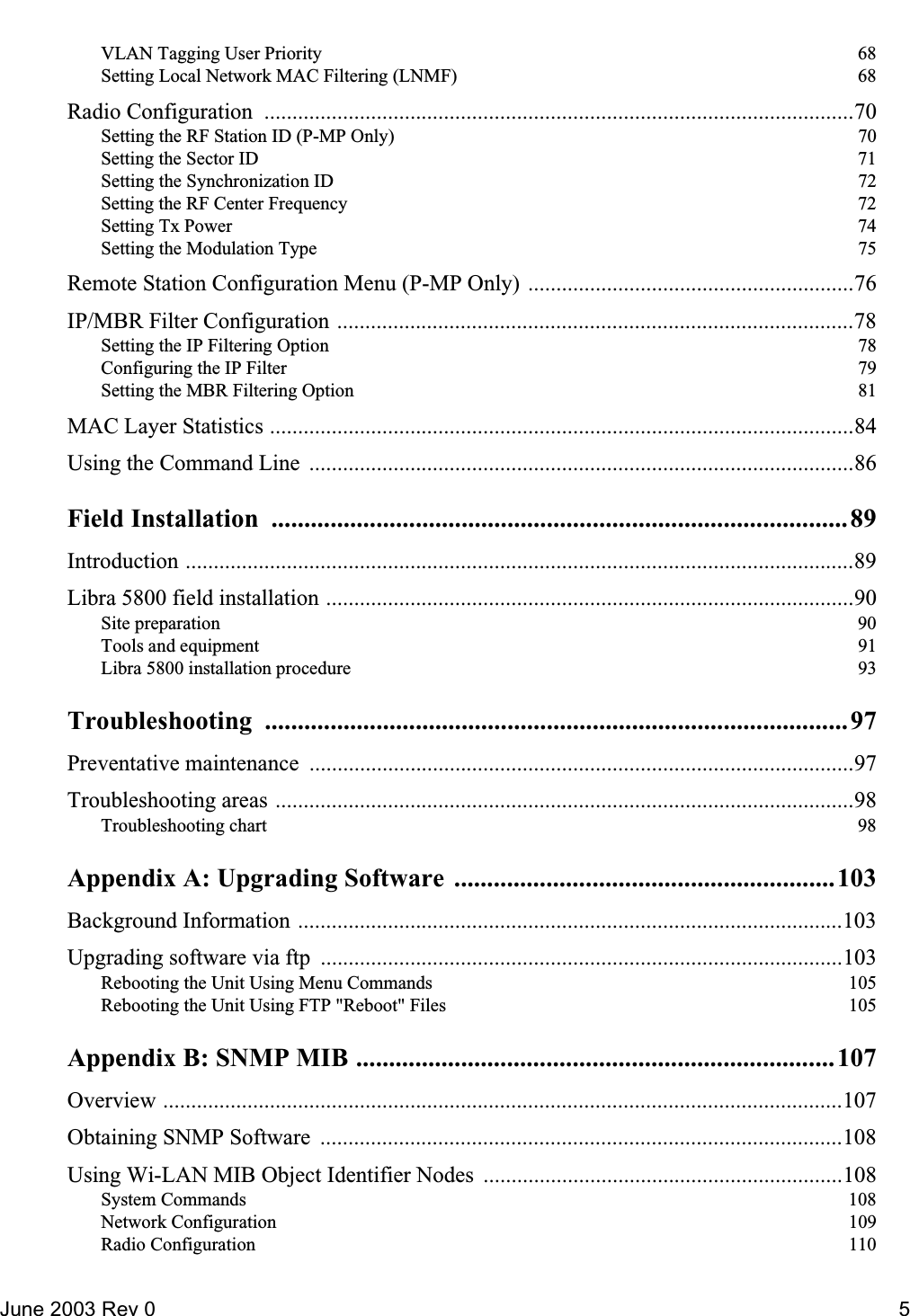
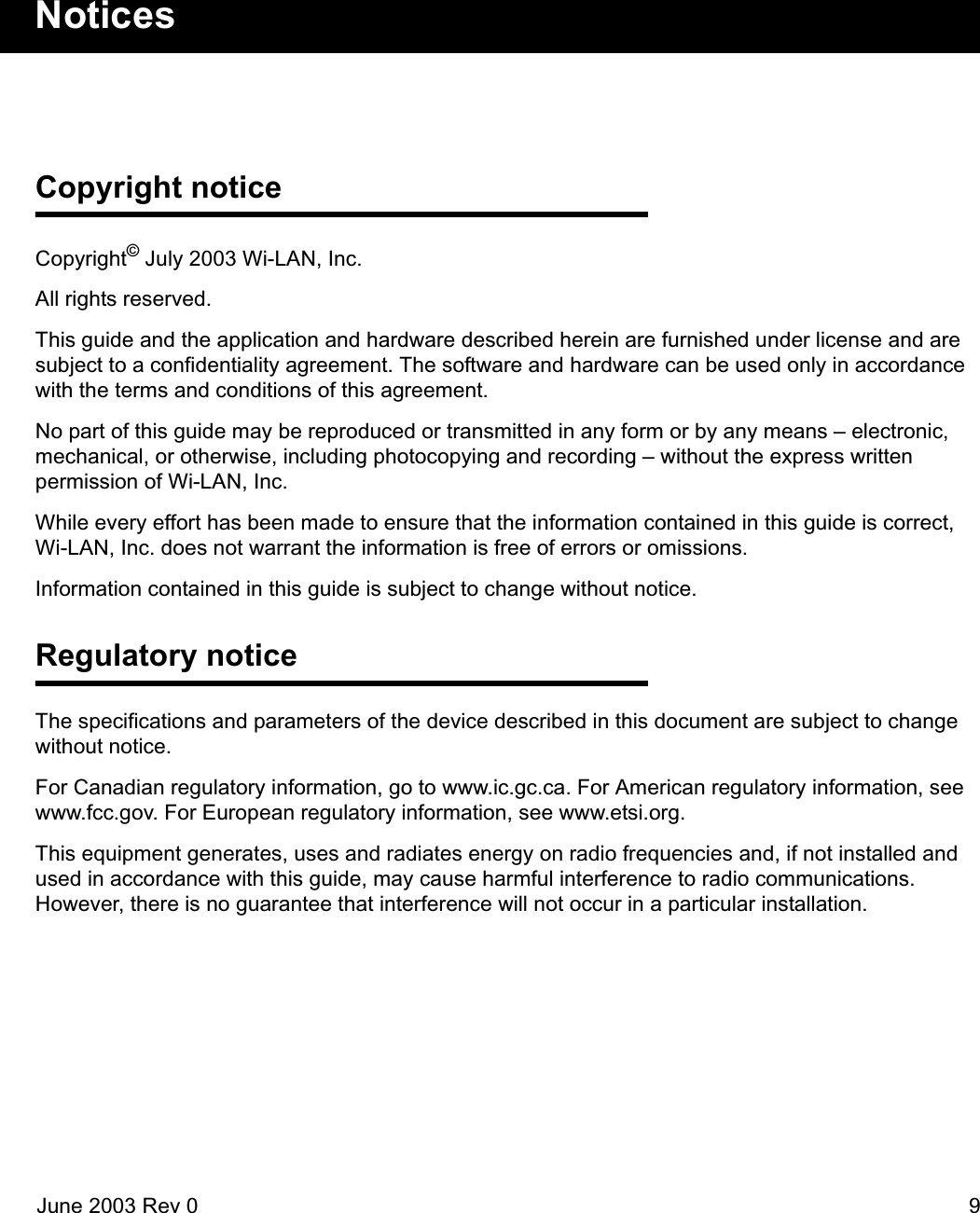

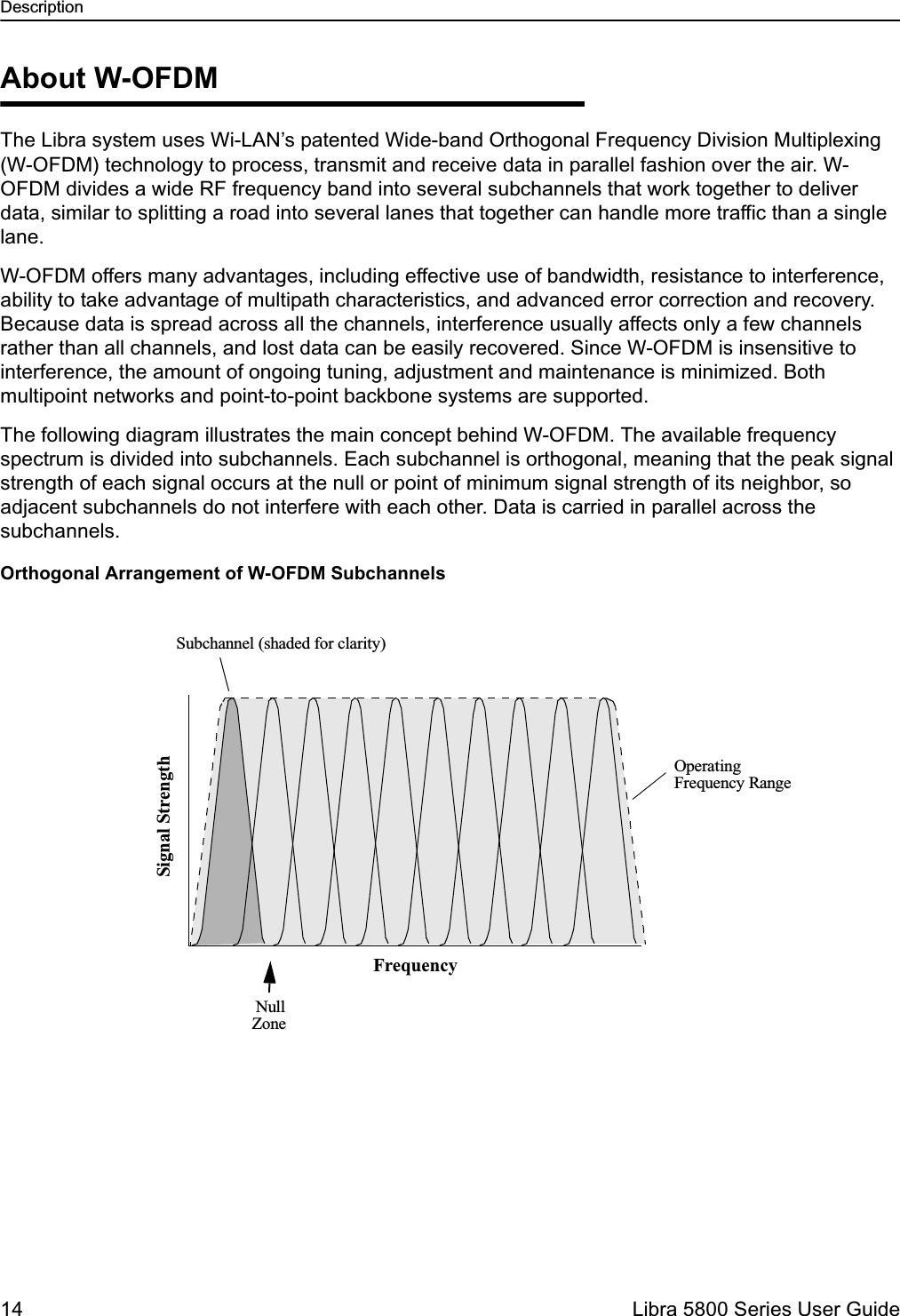

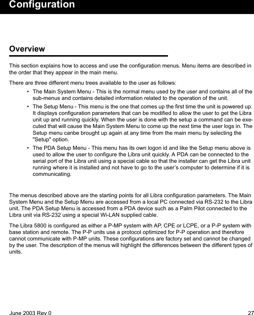
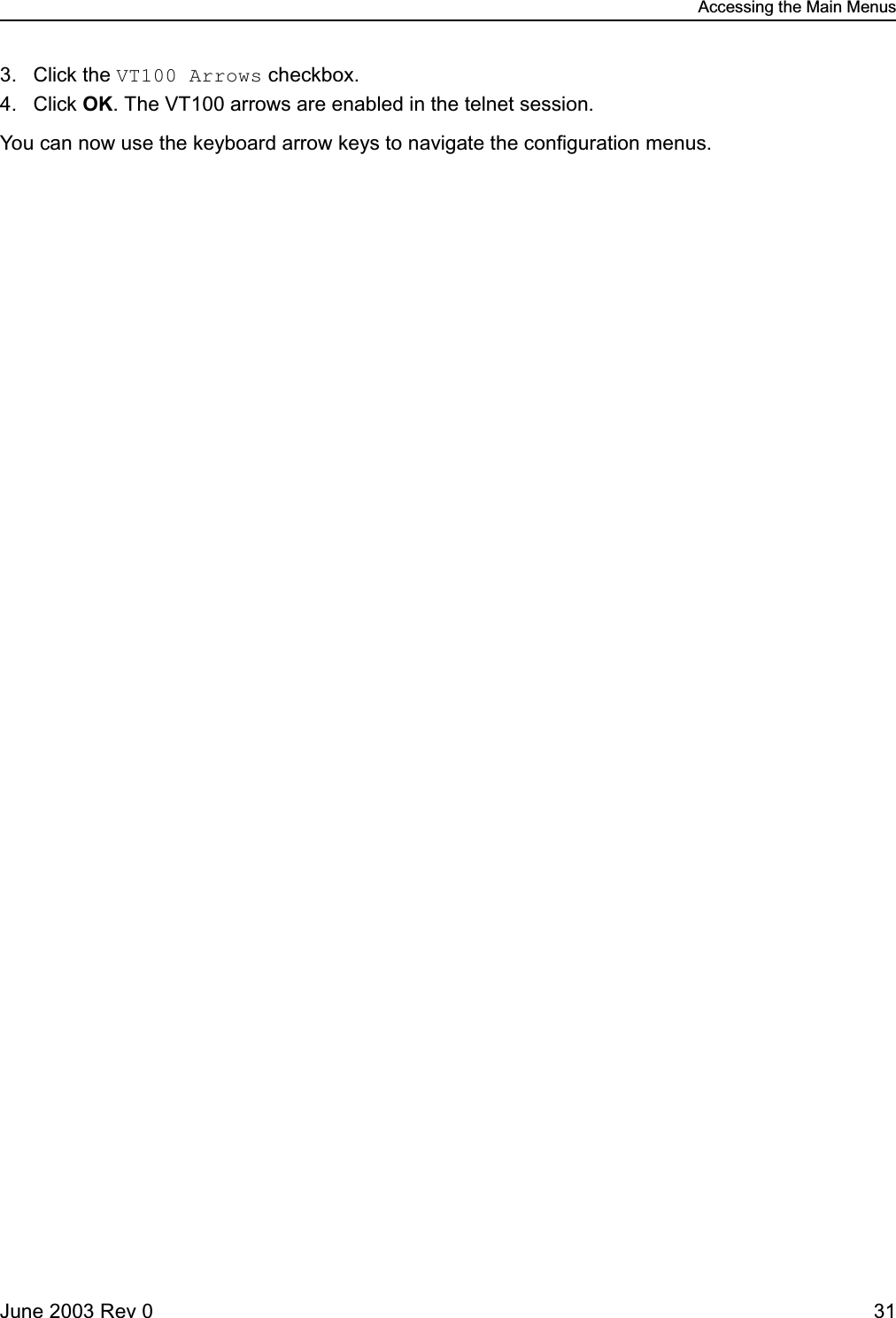
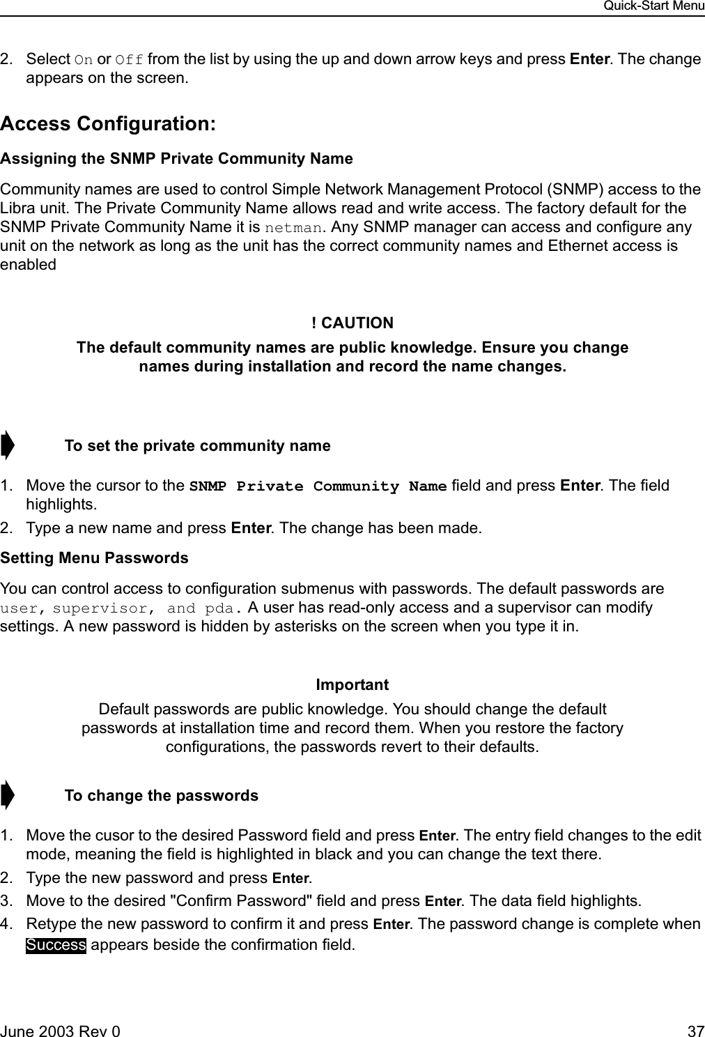
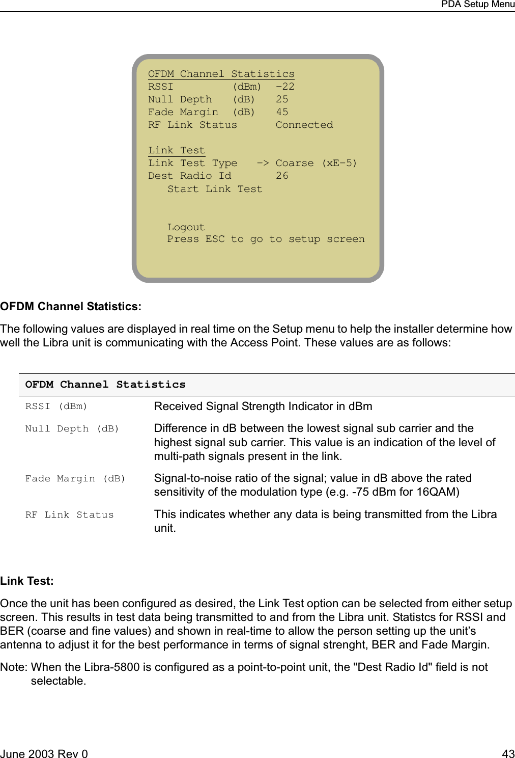
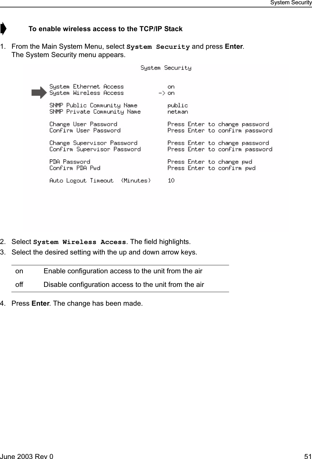
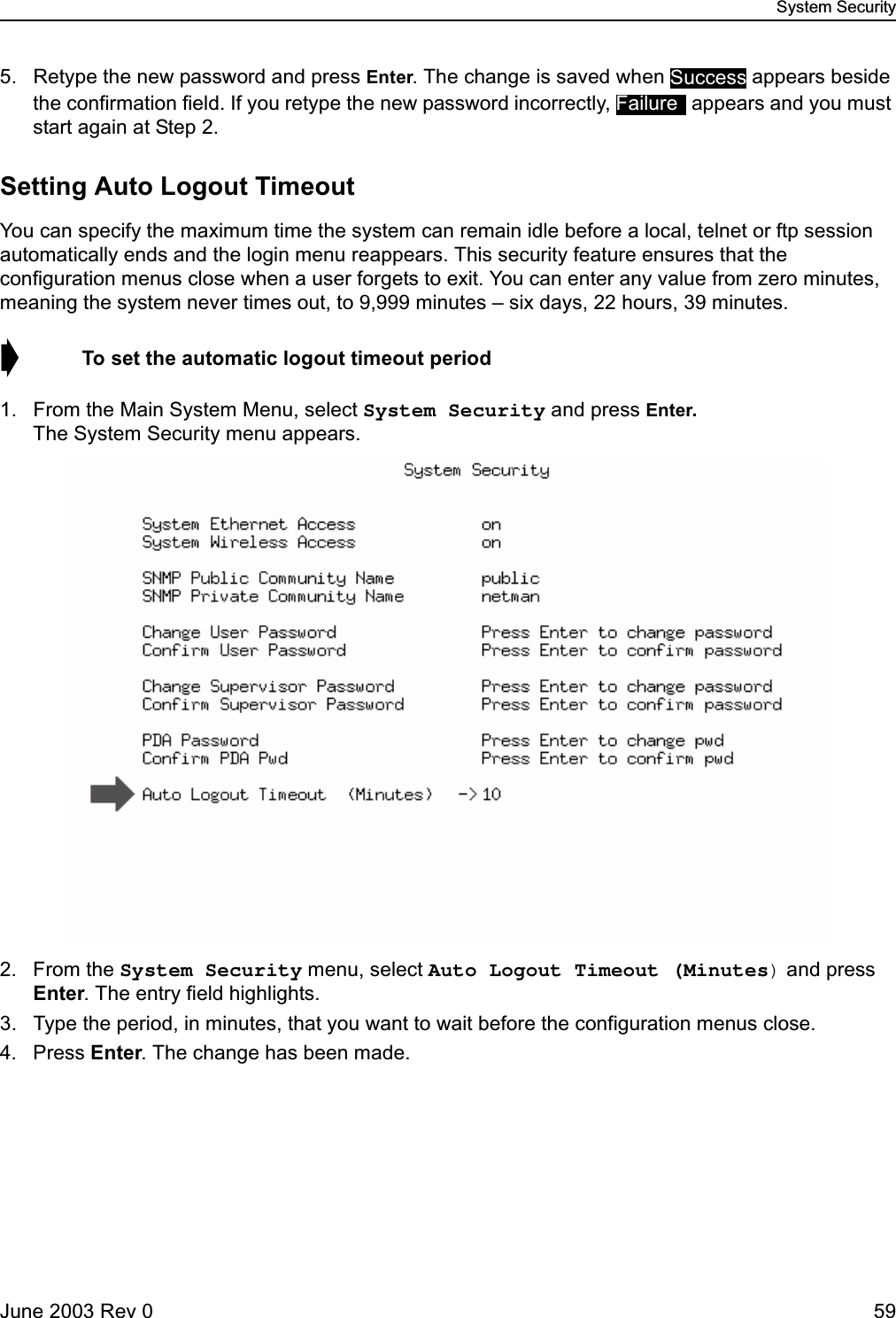
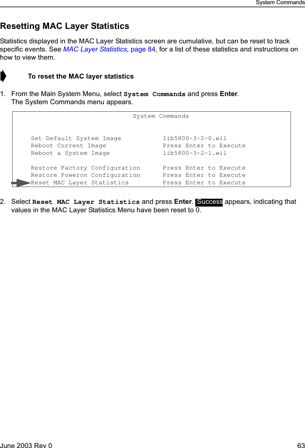
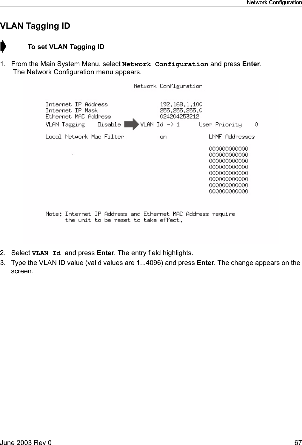
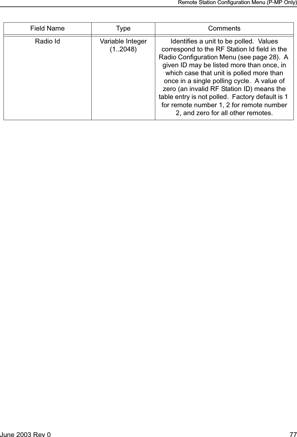
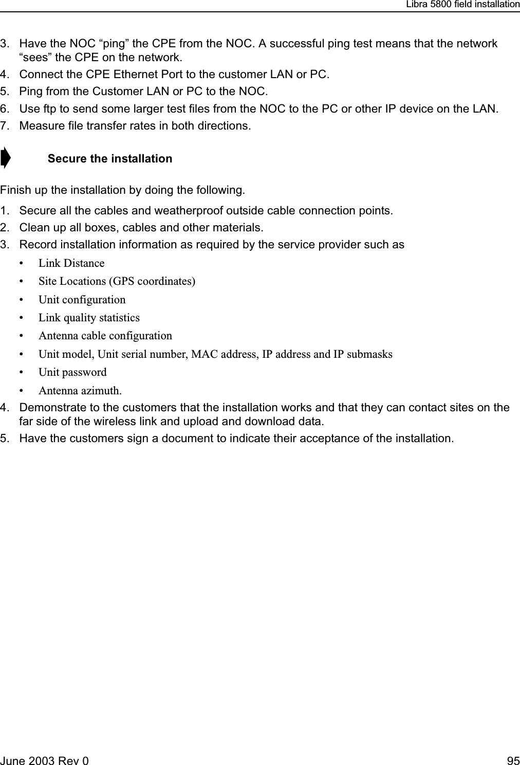
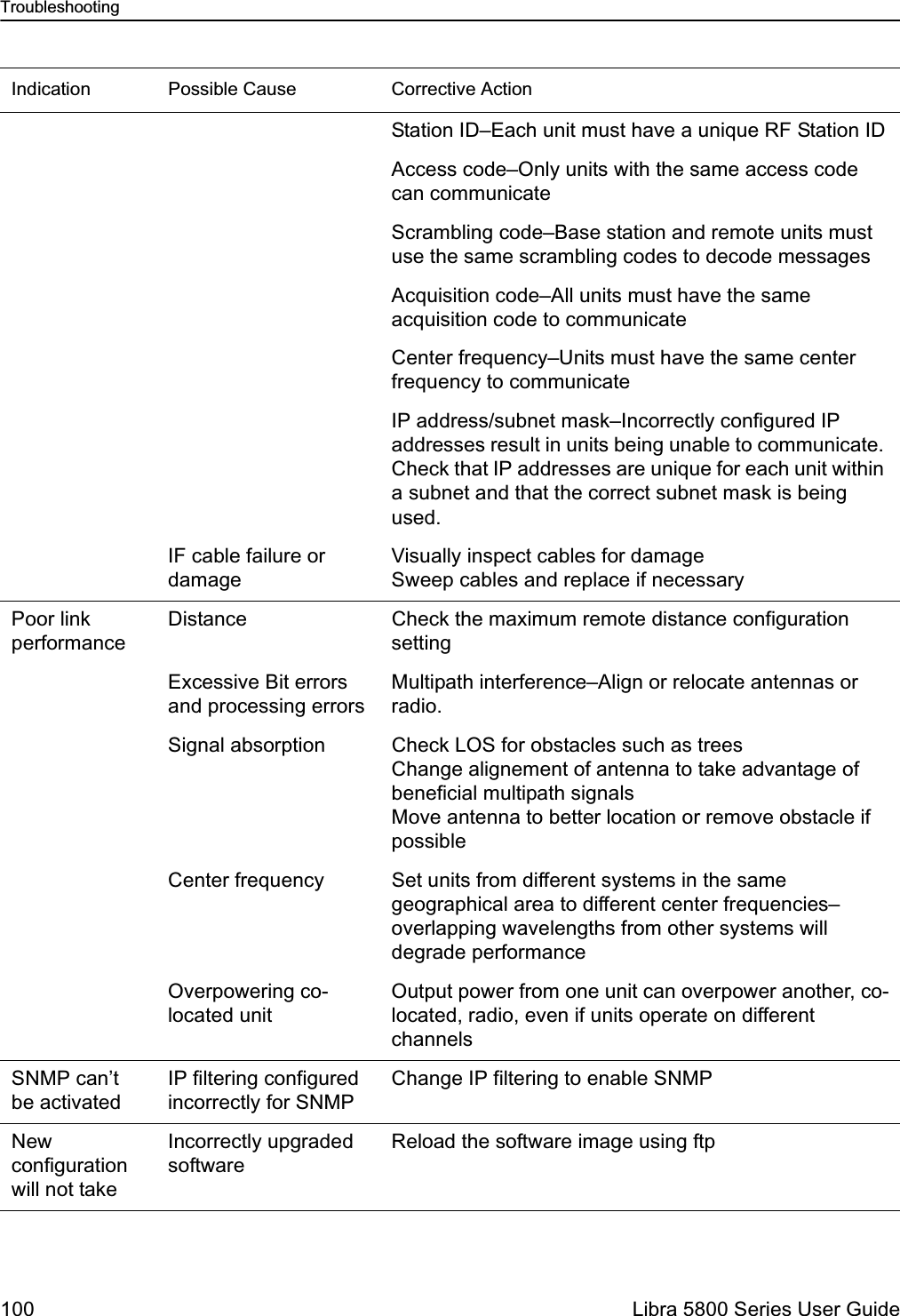
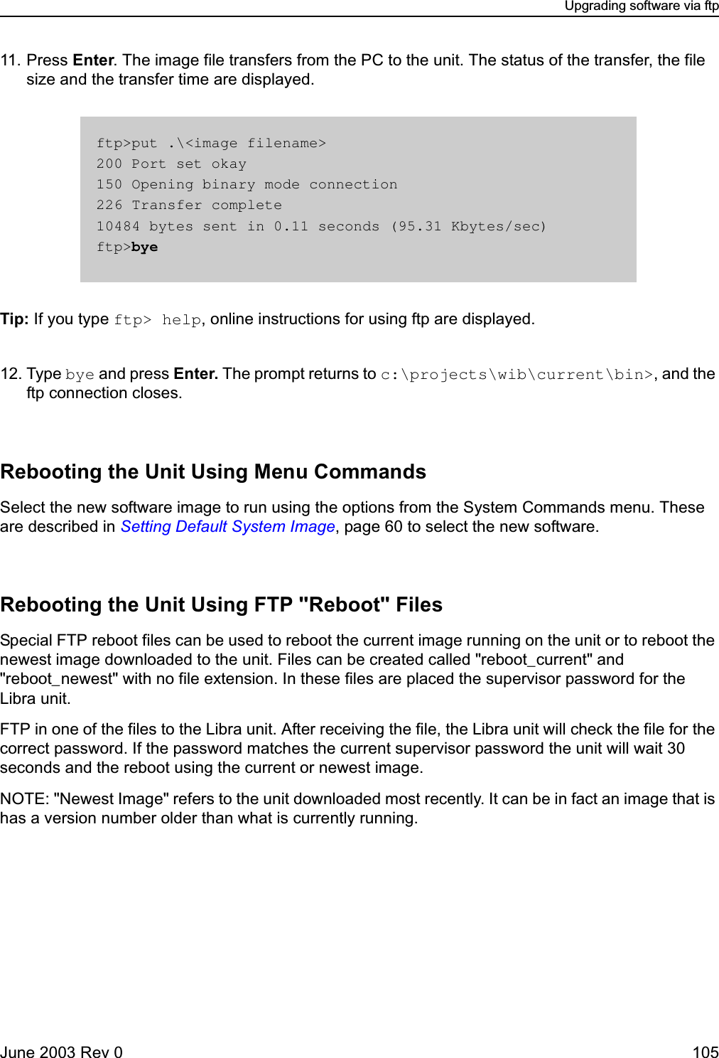
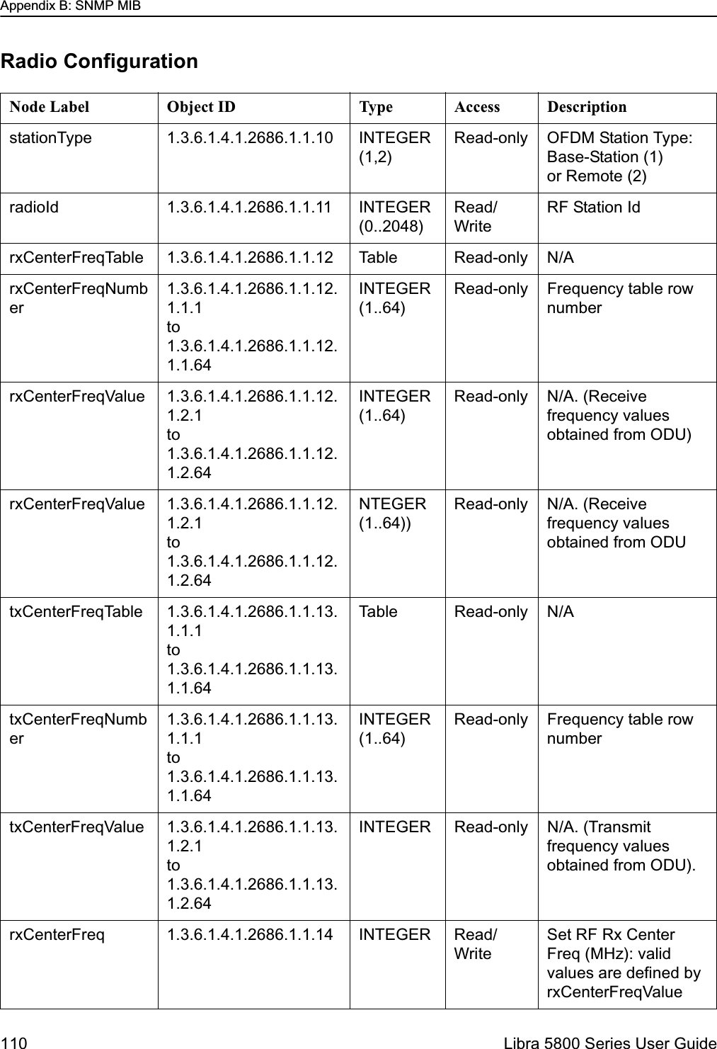
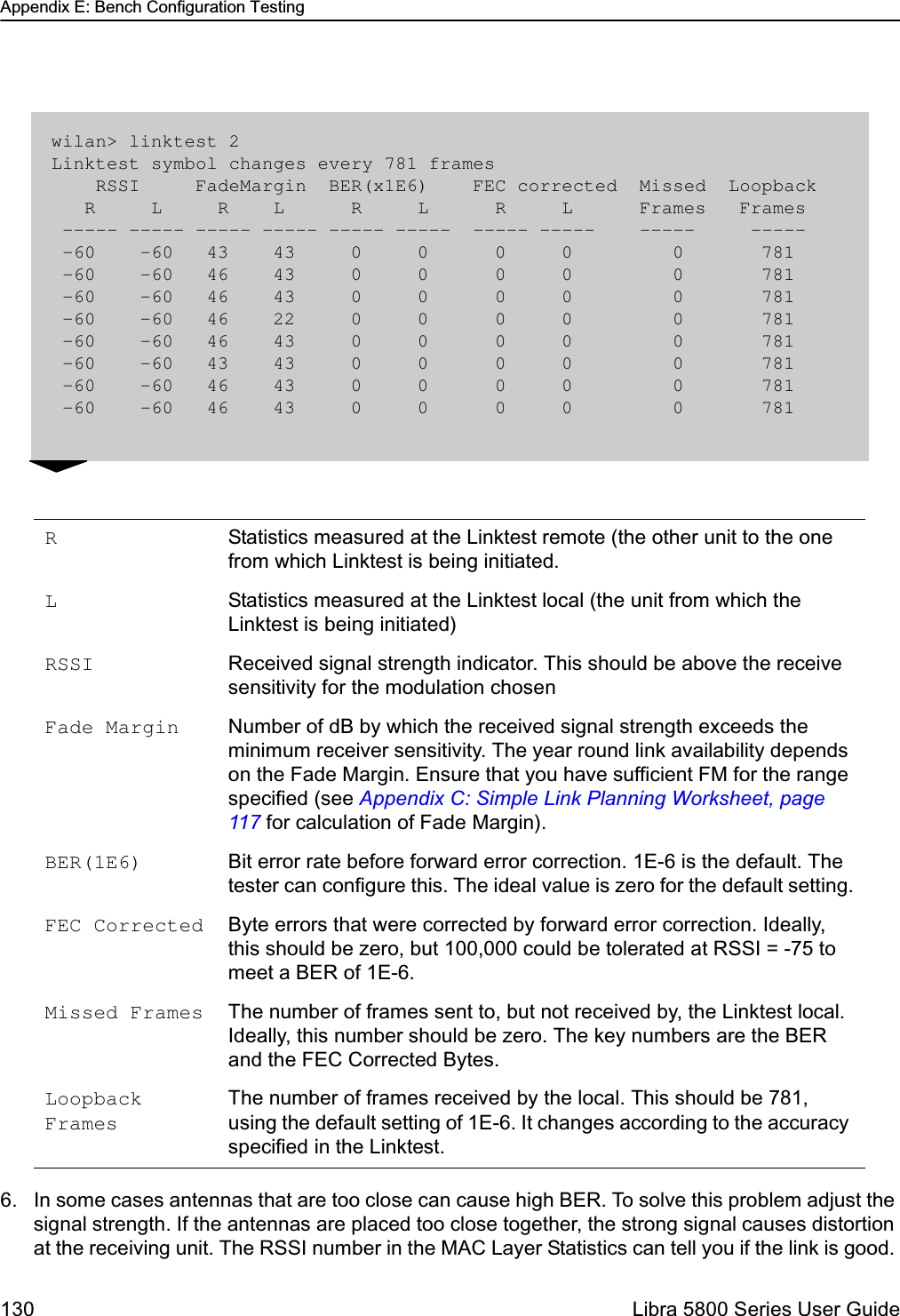
![Quick-Start MenuJune 2003 Rev 0 33Quick-Start MenuWhen the Libra unit starts up for the very first time, it will start up in setup mode. This a single screen as shown below that displays all of the parameters that the user needs to set up the unit and get it talking with the base station.Many of the fields on this menu can be found in more detailed menus as discussed later on in this section.Exiting SetupWhen the setup procedure is complete and the unit has been re-booted to activate all the changes you can exit the setup procedure.➧ To exit setup1. Move the cursor to the Exit setup and logout field and press Enter. Libra Model 5800 - 12.5 MHz Setup Menu Unit Configuration Communication Parameters RF Station Id [1..2048] -> 2 Internet IP Address 192.168.1.100 Sector Id [0..31] 1 Internet IP Mask 255.255.255.0 Synchronization Id [0..1] 0 System Ethernet Access on Local Network Mac Filter off Radio Configuration Access Configuration Modulation Type QAM 16 SNMP Priv Community netman Tx Power [-14..17] 17 Super Password Press Enter to change pwd Rx Center Freq (kHz) 5787000 Confirm Super Pwd Press Enter to confirm pwd Tx Center Freq (kHz) 5787000 User Pwd Press Enter to change pwd Confirm User Pwd Press Enter to confirm pwd OFDM Channel Statistics PDA Password Press Enter to change pwd RSSI (dBm) -22 Confirm PDA Pwd Press Enter to confirm pwd Null Depth (dB) 0 Fade Margin (dB) 53 Link Test RF Link Status Not Connected Link Test Type Coarse (xE-5) Dest Radio Id [1..2048] 9 Start Link Test Activate changes and reboot Exit setup and logout](https://usermanual.wiki/Wi-Lan/EB05/User-Guide-359940-Page-33.png)
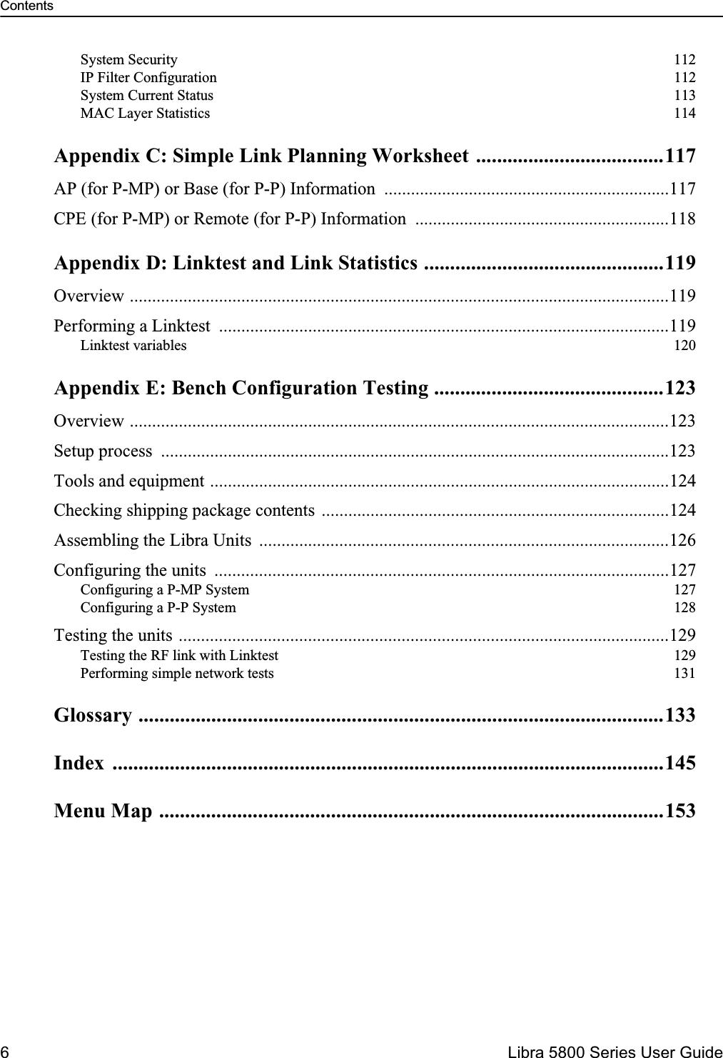
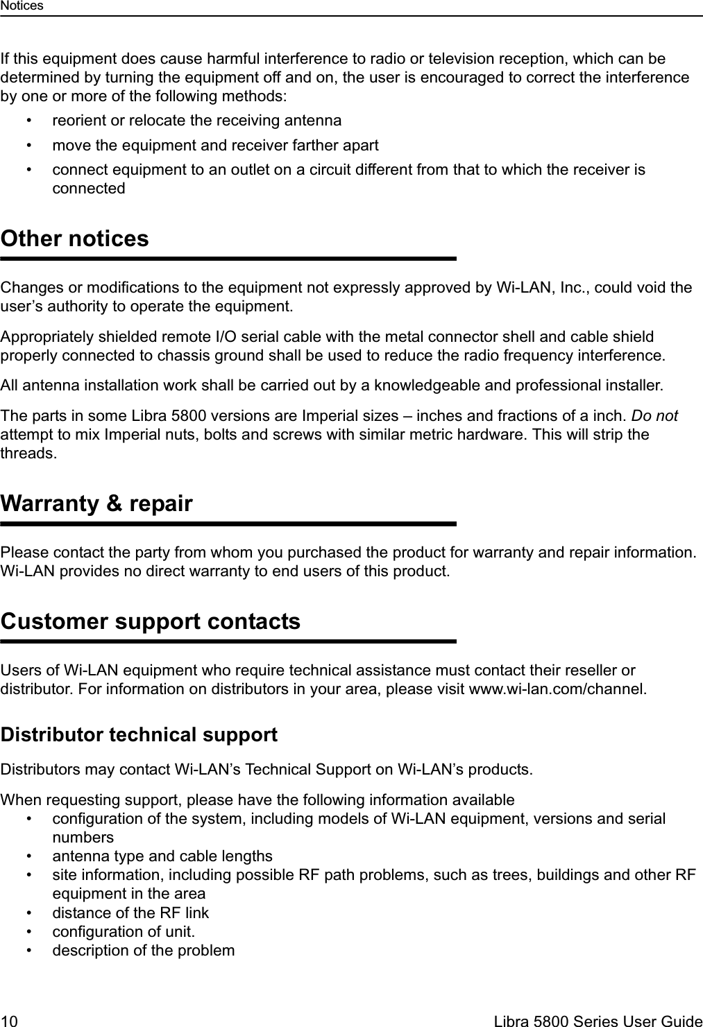
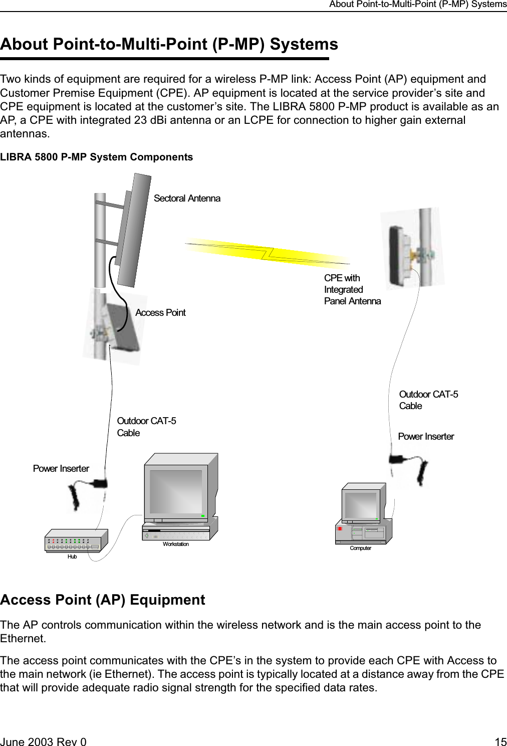
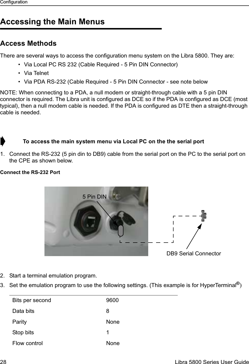
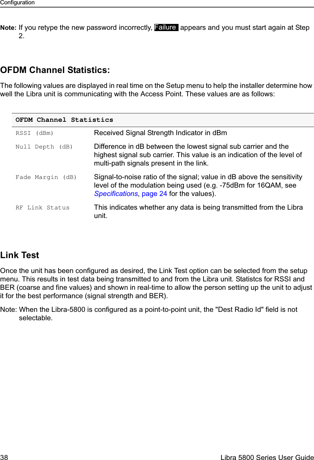
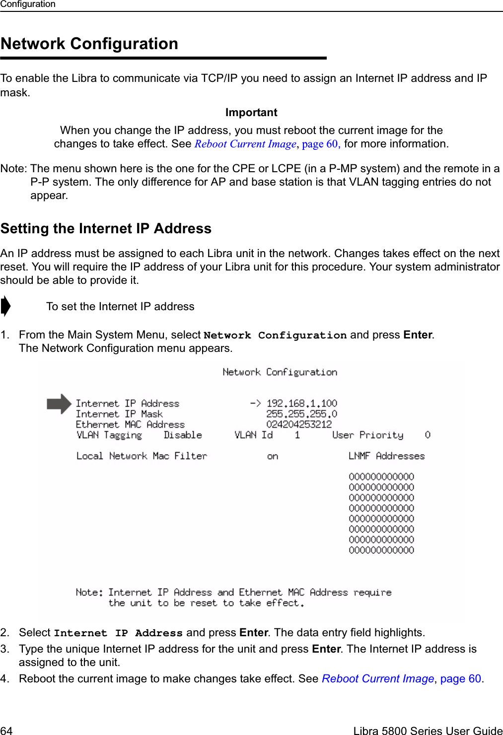
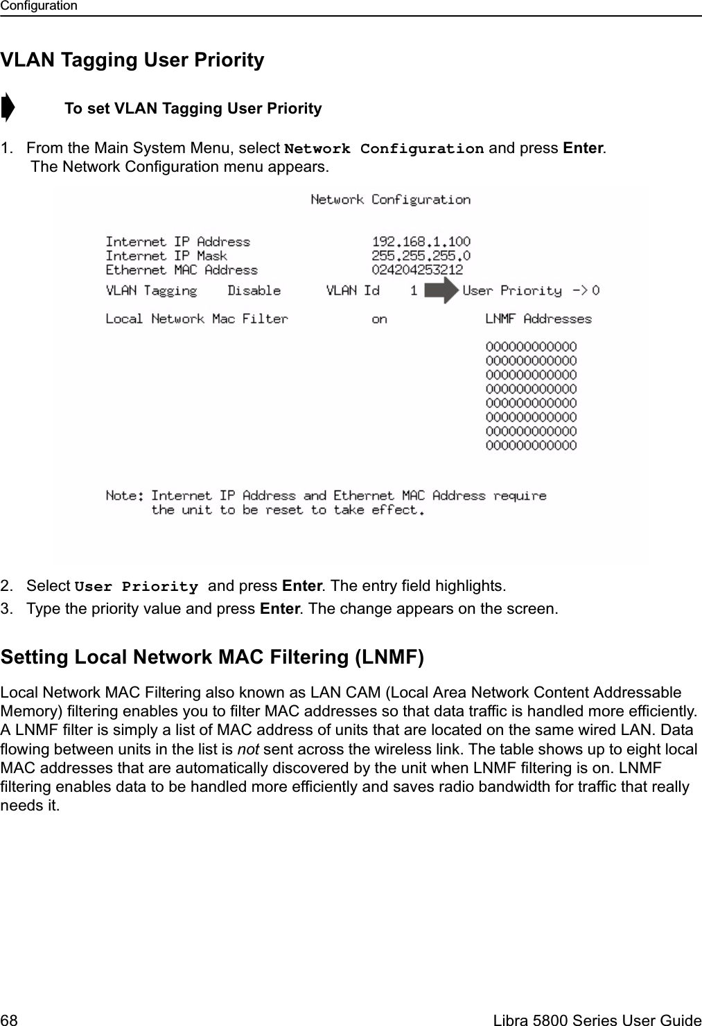
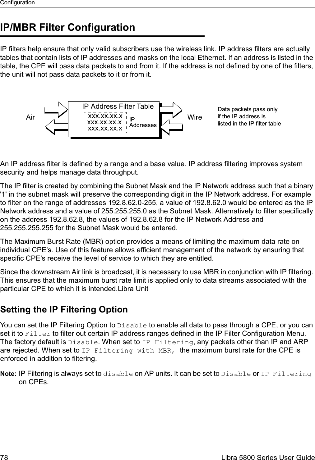
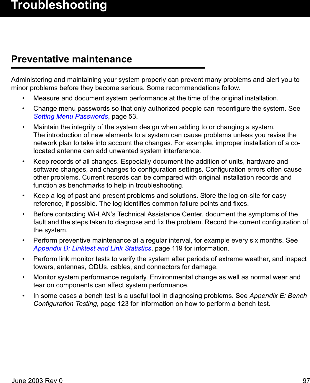
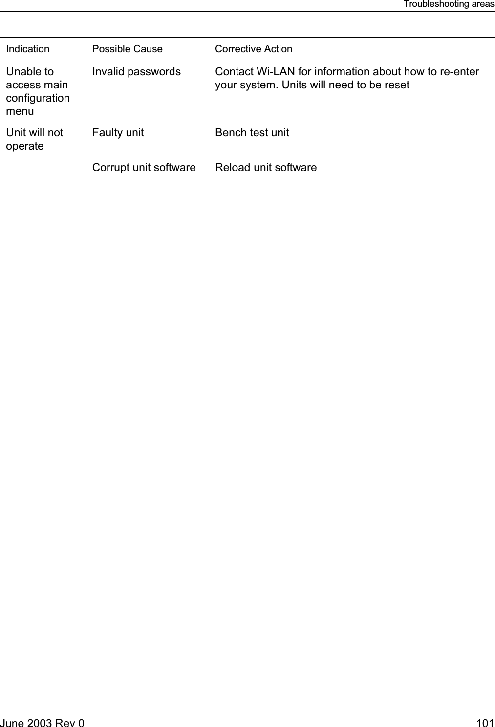
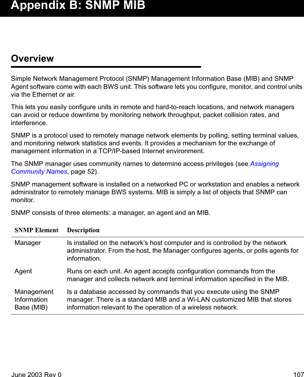
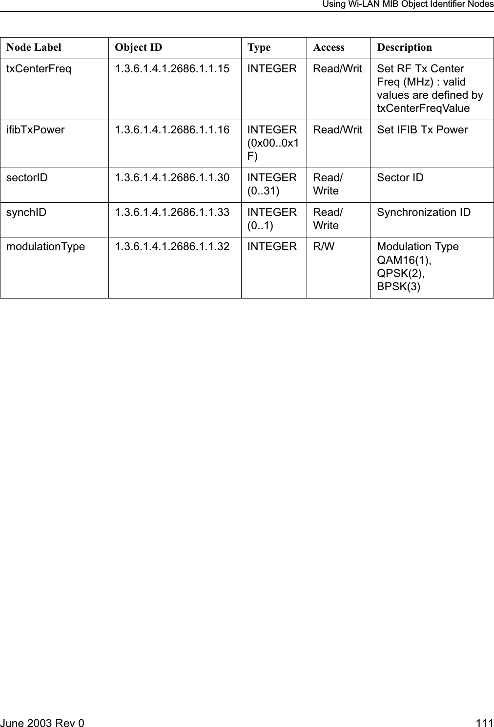
![Configuration34 Libra 5800 Series User GuideUnit Configuration:Setting the RF Station IDEach Libra unit requires a unique RF Station ID to identify it on the network. Every unit must have a unique RF Station ID. No two units may have the same ID. In a P-P system you cannot access this selection. ➧ To set the RF station ID1. Select RF Station Id [1..2047] and press Enter. The entry field highlights.2. Type a unique number for the RF Station ID and press Enter. Zero is not a valid Station ID.3. Record the RF Station ID you have assigned to the unit.You will need to know this number when you configure the polling list on the Access Point.4. Reboot the system to effect the changes unless there are more changes you would like to make at this time. To do this move the cursor down to the line, "Activate changes and reboot" and press Enter Setting the Sector IDEach Libra unit can have a Sector ID to identify its AP within the cell on the network. This prevents Libra units from accessing different APs which may have the same Center Frequency.➧ To set the Sector ID1. Move the cursor to the Sector Id [0..31] field and press Enter. The entry field highlights.2. Type a unique number for the Sector ID and press Enter.3. Reboot the system to effect the changes unless there are more changes you would like to make at this time. To do this move the cursor down to the line, "Activate changes and reboot" and press Enter Setting the Synchronization IDBecause of OFDM’s superior multipath performance it is possible for the Libra to falsely synchronize on an AP from a different sector operating at the same frequency. In order to avoid this type of error, the APs and Libras of each sector can have one of two possible OFDM synchronization patterns. These patterns are orthogonal, thus a Libra with a given Synchronization ID will never synch to an AP with the other synch. Every Libra in the sector must have the same Synchronization ID as the AP of that sector. ➧ To set the Synchronization ID1. Move the cursor to the Synchronization Id [0..1] field and press Enter. The entry field highlights.2. Type a 0 or 1 to select the Synchronization ID and press Enter. Factory default is zero (0).3. Reboot the system to effect the changes unless there are more changes you would like to make at this time. To do this move the cursor down to the line, "Activate changes and reboot" and press Enter. Setting the Modulation Type](https://usermanual.wiki/Wi-Lan/EB05/User-Guide-359940-Page-34.png)
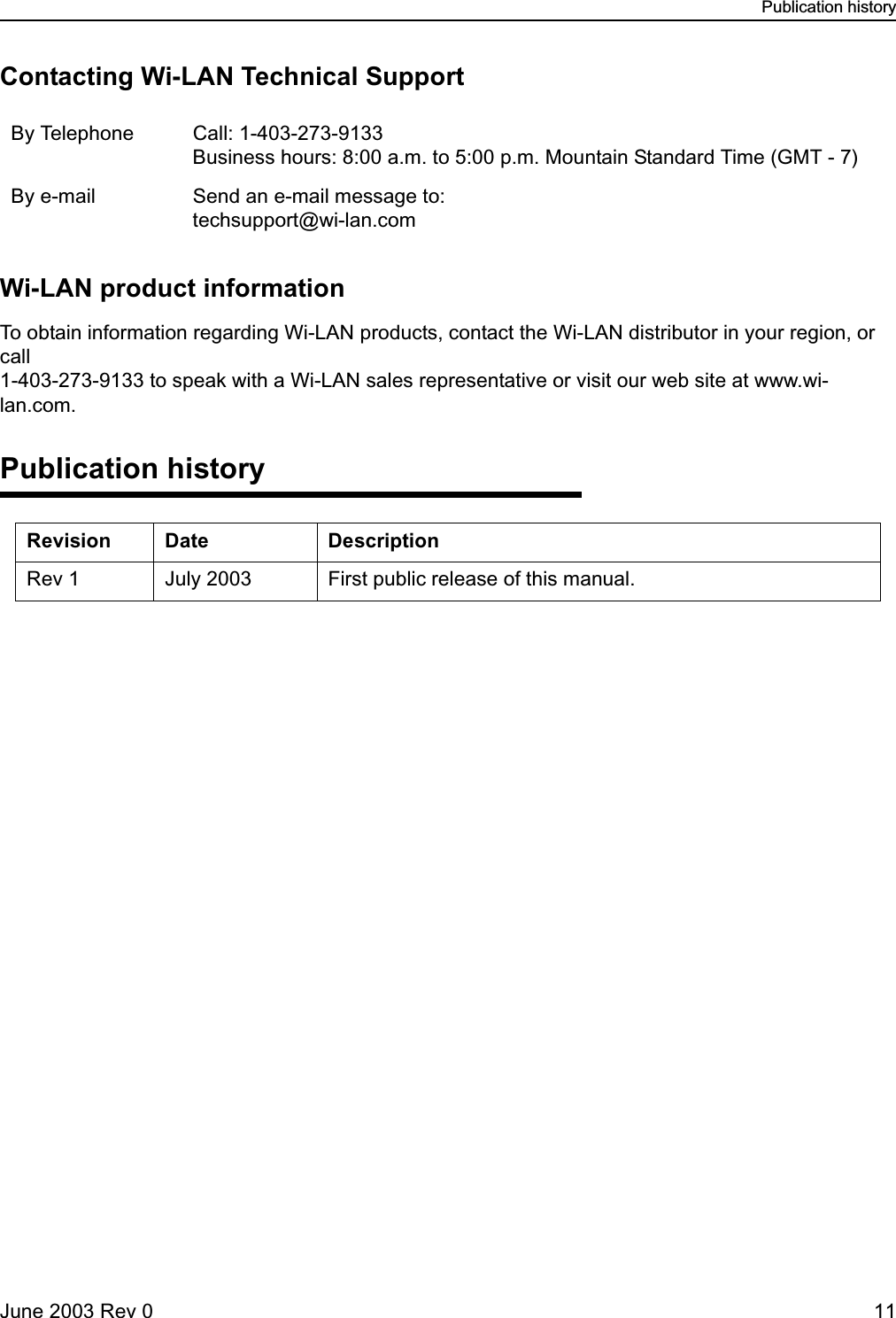
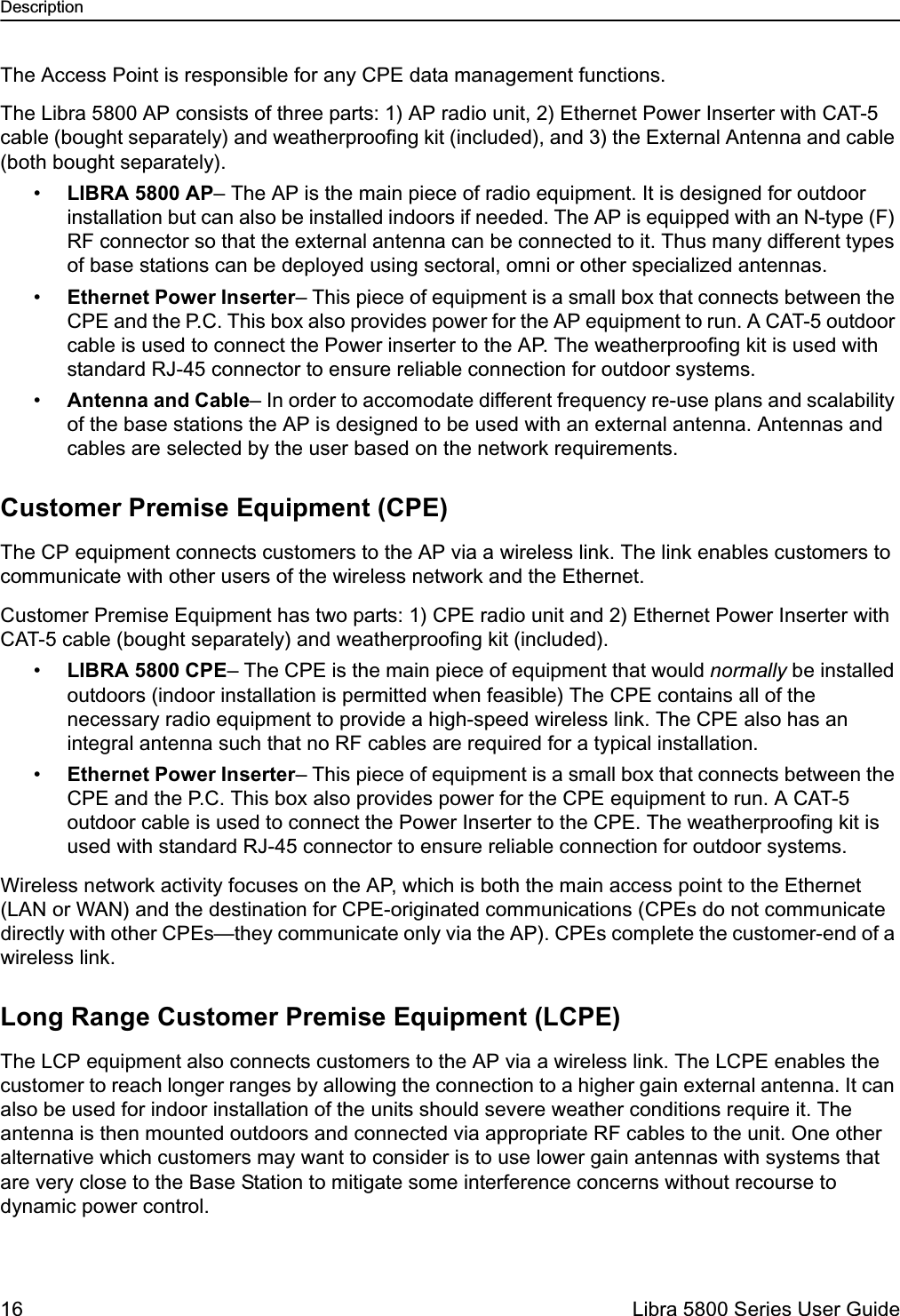
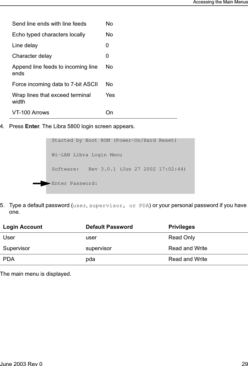
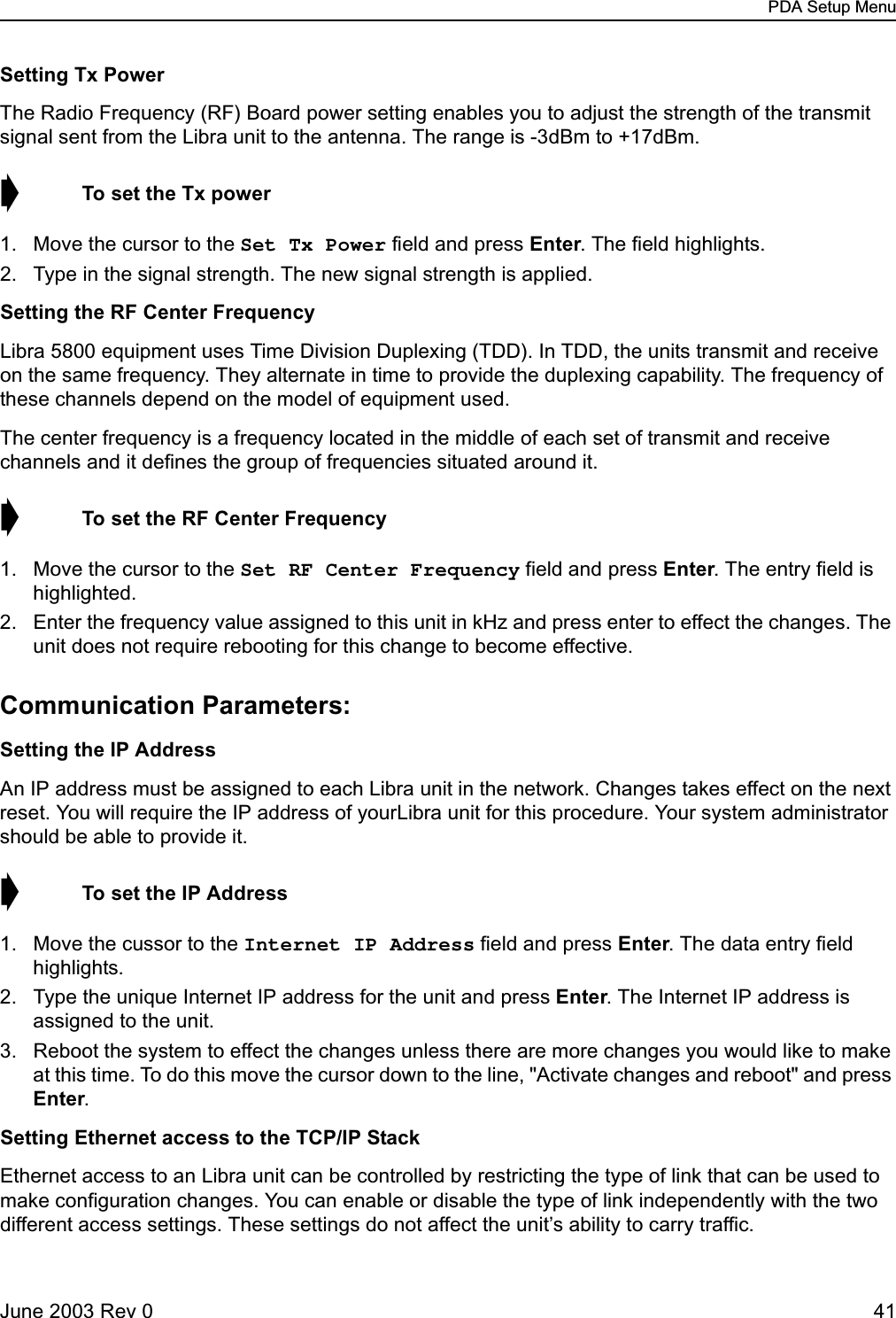
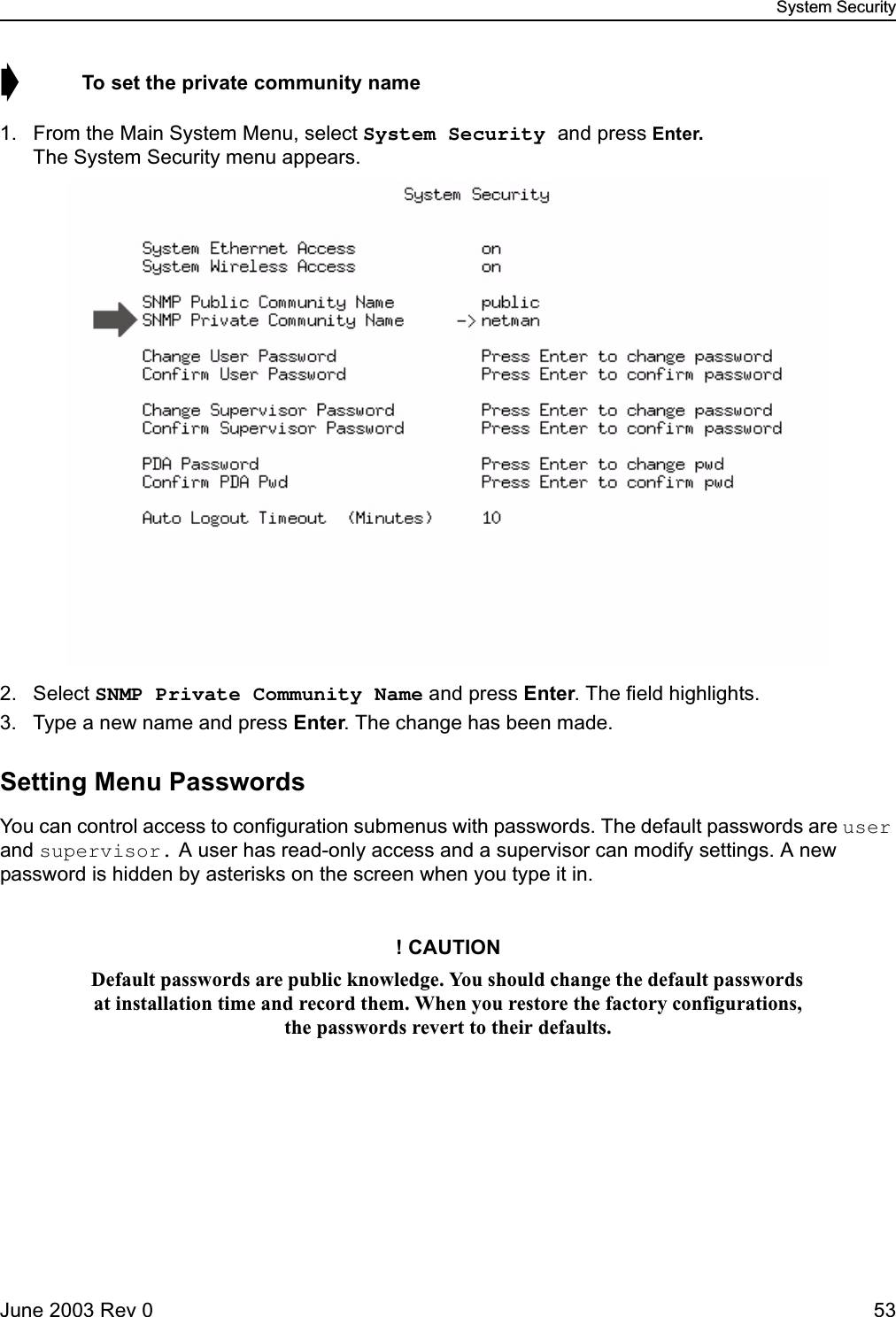
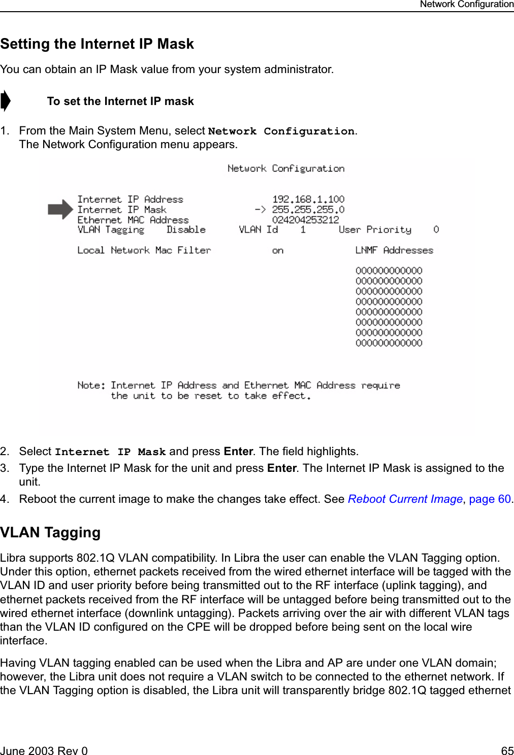
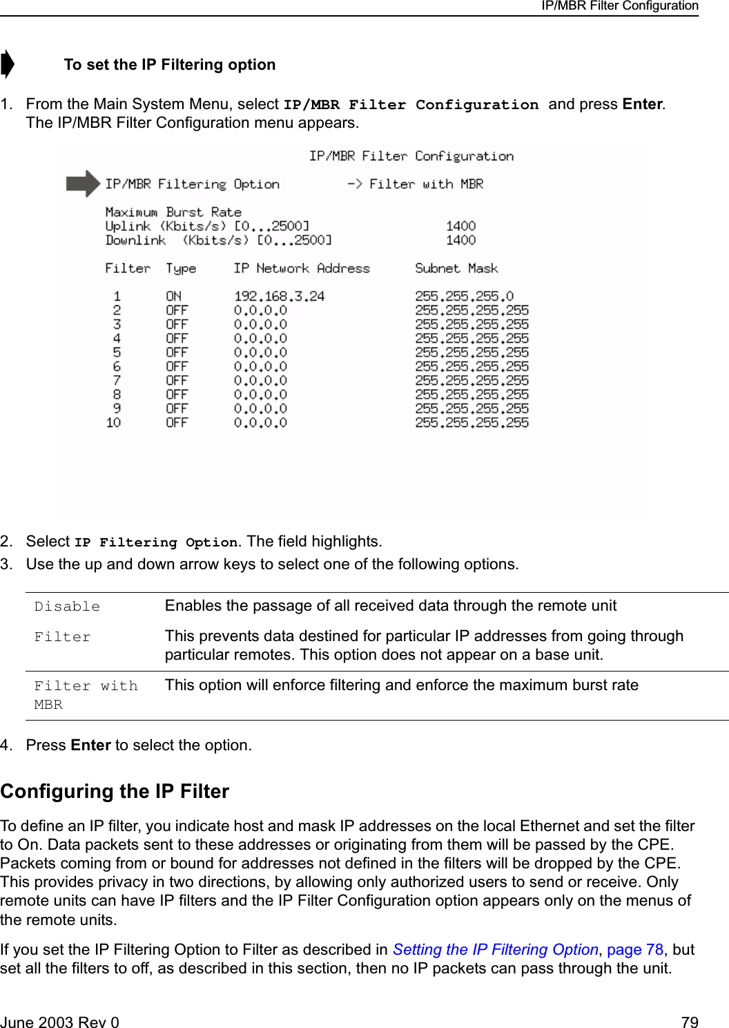
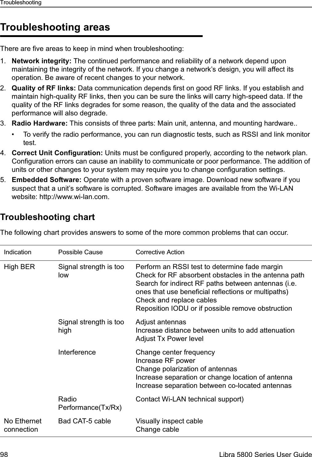
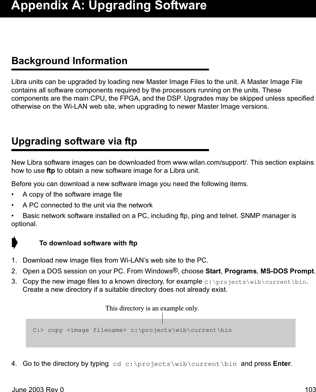
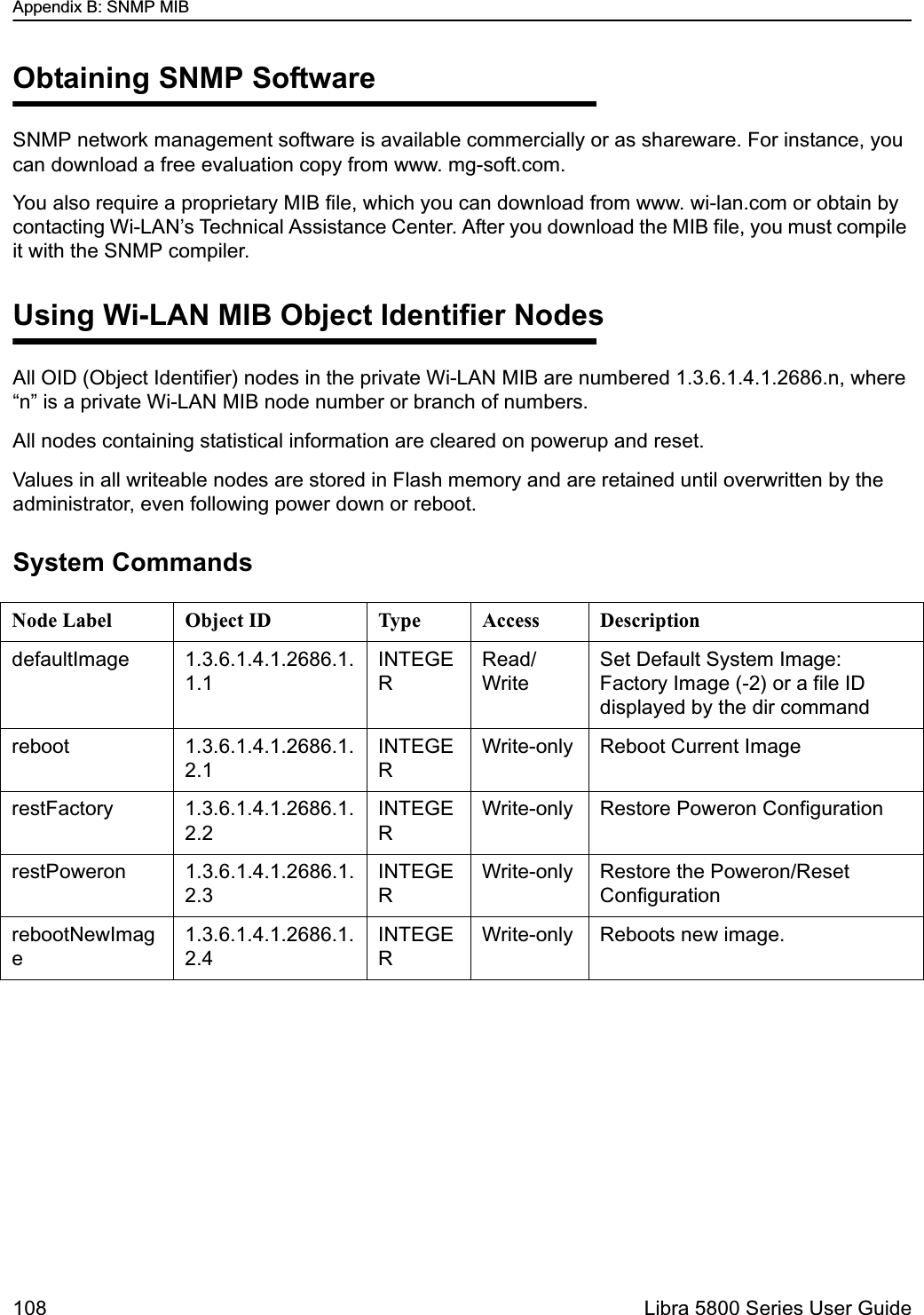
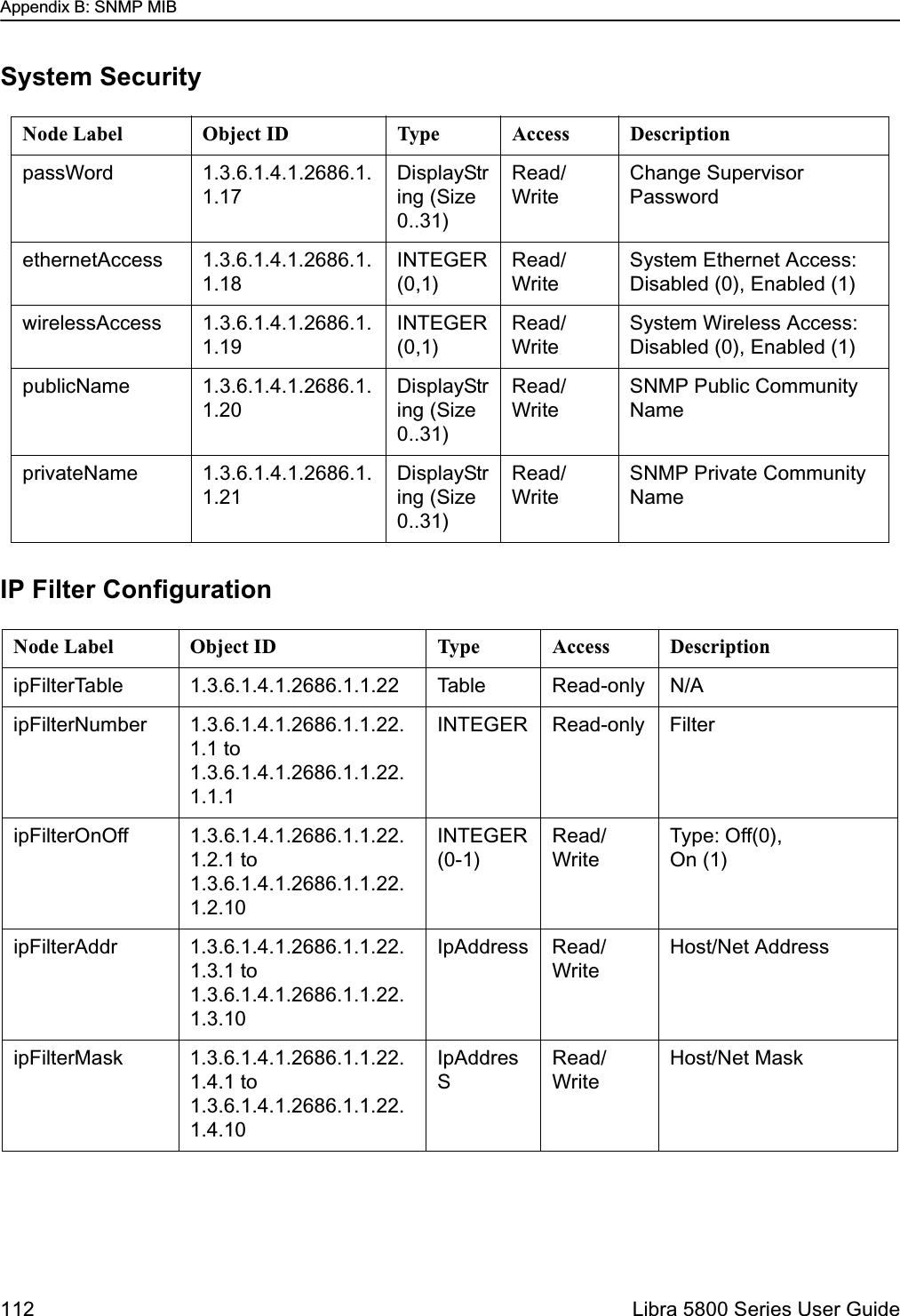
![PDA Setup MenuJune 2003 Rev 0 39PDA Setup MenuWhen logging into the unit using the PDA login, it will come up in setup mode. This is in the form of two screens that display all of the parameters that the user needs to set up the unit and get it talking with the base station.Many of the fields on this menu can be found in more detailed menus available when using a PC as discussed later on in this section.Unit Configuration:Setting the RF Station IDEach Libra unit in a P-MP network requires a unique RF Station ID to identify it on the network. Every unit must have a unique RF Station ID. No two units may have the same ID. In P-P system you cannot access this selection. ➧ To set the RF station ID1. Select RF Station Id [1..2048] and press Enter. The entry field highlights.2. Type a unique number for the RF Station ID and press Enter. Zero is not a valid Station ID.3. Record the RF Station ID you have assigned to the unit.You will need to know this number when you configure the polling list on the Access Point.4. Reboot the system to effect the changes unless there are more changes you would like to make at this time. To do this move the cursor down to the line, "Activate changes and reboot" and press EnterLibra Setup RF Station Id [1..2048] -> 244 Sector Id [0..31] 7 Synchronization Id [0..1] 0 Modulation Type QAM 16 Tx Power [-14..17] 17 Rx Center Freq (kHz) 5787000 Tx Center Freq (kHz) 5787000 Internet IP Address 192.168.1.100 System Ethernet Access on Local Network Mac Filter off Monitor Screen Logout Activate changes and reboot](https://usermanual.wiki/Wi-Lan/EB05/User-Guide-359940-Page-39.png)
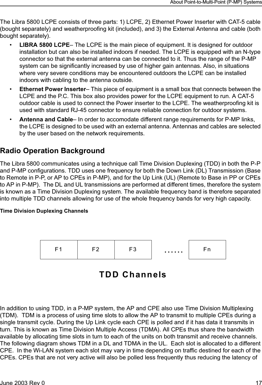
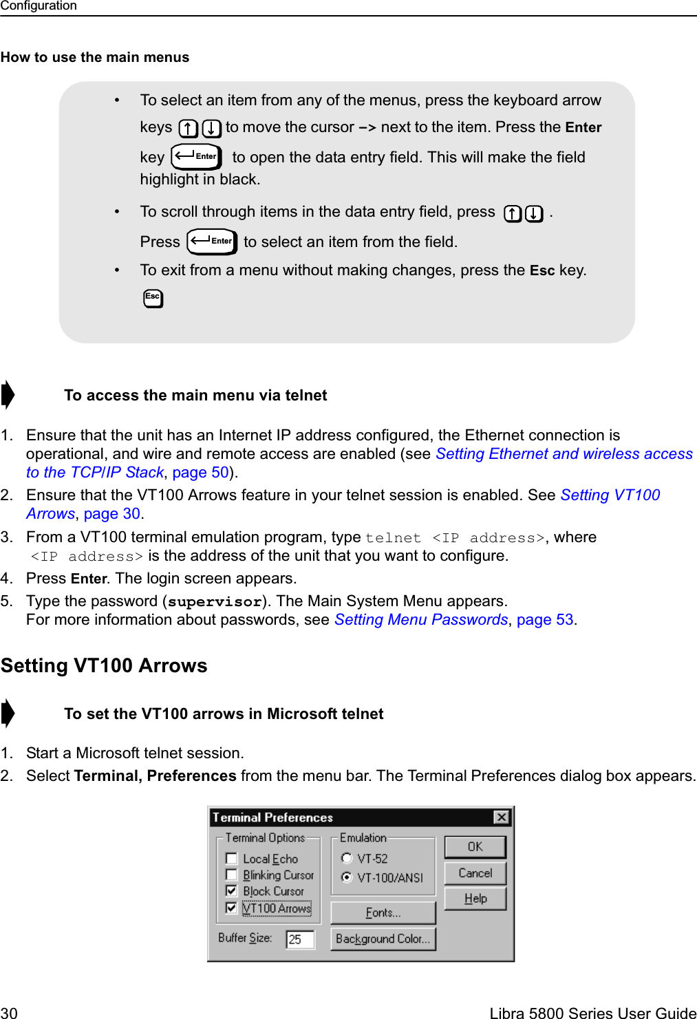
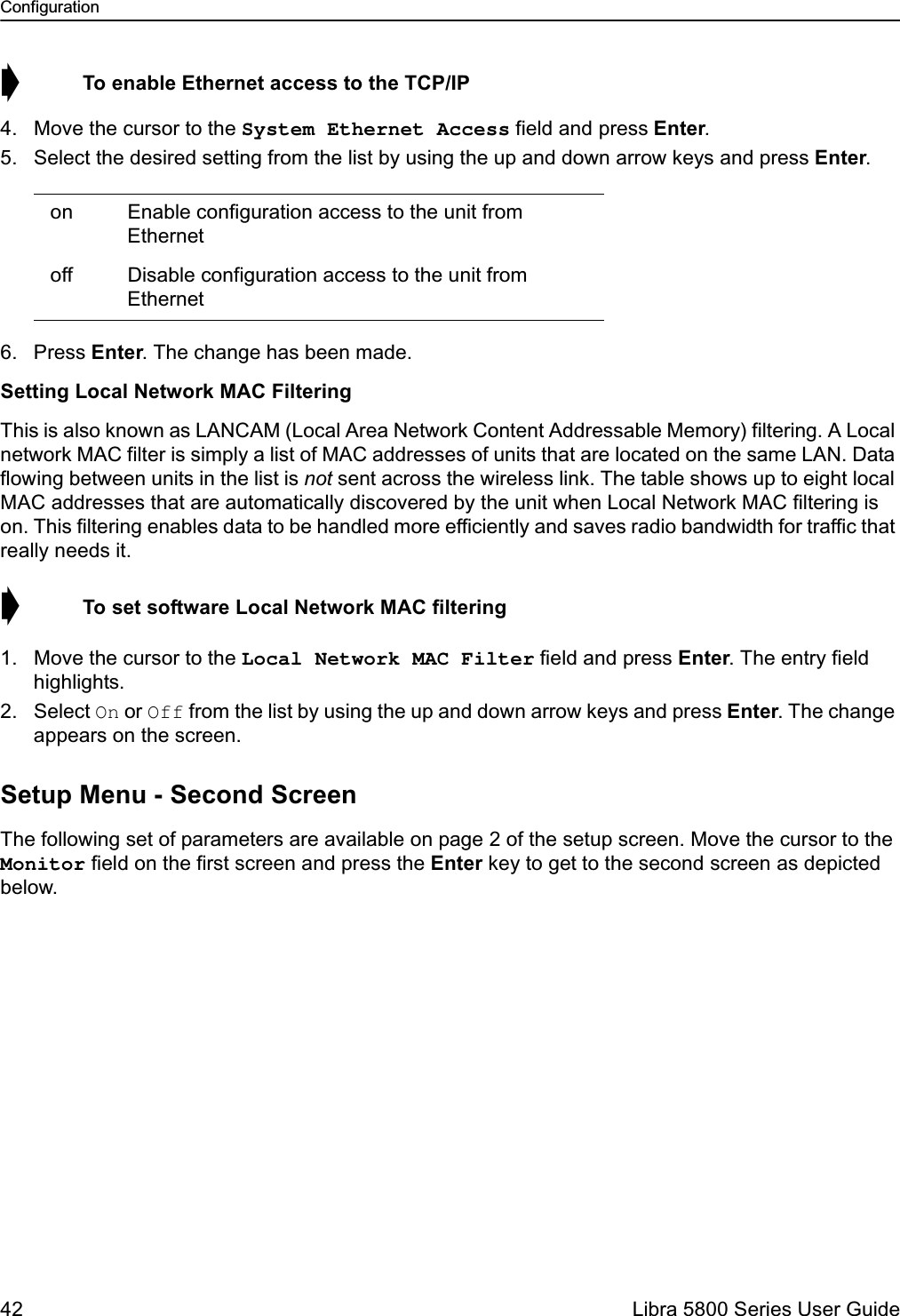
![Configuration40 Libra 5800 Series User GuideSetting the Sector IDEach Libra unit can have a Sector ID to identify its AP/Base within the network. This prevents Libra units from accessing different APs which may have the same Center Frequency.➧ To set the Sector ID1. Move the cursor to the Sector Id [0..31] field and press Enter. The entry field highlights.2. Type a unique number for the Sector ID and press Enter.3. Reboot the system to effect the changes unless there are more changes you would like to make at this time. To do this move the cursor down to the line, "Activate changes and reboot" and press EnterSetting the Synchronization IDBecause of OFDM’s superior multipath performance it is possible for the Libra to falsely synchronize on an AP from a different sector operating at the same frequency. In order to avoid this type of error, the APs and Libras of each sector can have one of two possible OFDM synchronization patterns. These patterns are orthogonal, thus a Libra with a given Synchronization ID will never synch to an AP with the other synch. Every Libra in the sector must have the same Synchronization ID as the AP of that sector. ➧ To set the Synchronization ID1. Move the cursor to the Synchronization Id [0..1] field and press Enter. The entry field highlights.2. Type a 0 or 1 to select the Synchronization ID and press Enter. Factory default is zero (0).3. Reboot the system to effect the changes unless there are more changes you would like to make at this time. To do this move the cursor down to the line, "Activate changes and reboot" and press Enter.Radio Configuration:Setting the Modulation TypeThe OFDM Modulation Type can be selected from among the following possible values: "QAM 16", "QPSK" and "BPSK". The selected type will be added to the next superframe transmitted.➧ To set the Modulation Type1. Move the cursor to the Modulation Type field and press Enter. The field highlights.2. Select from the list using the up and down arrow keys the Modulation type and press Enter. The possible options are: QAM 16, QPSK, and BPSK. The new modulation type is applied to the next superframe to be transmitted.3. Reboot the system to effect the changes unless there are more changes you would like to make at this time. To do this move the cursor down to the line, "Activate changes and reboot" and press Enter](https://usermanual.wiki/Wi-Lan/EB05/User-Guide-359940-Page-40.png)
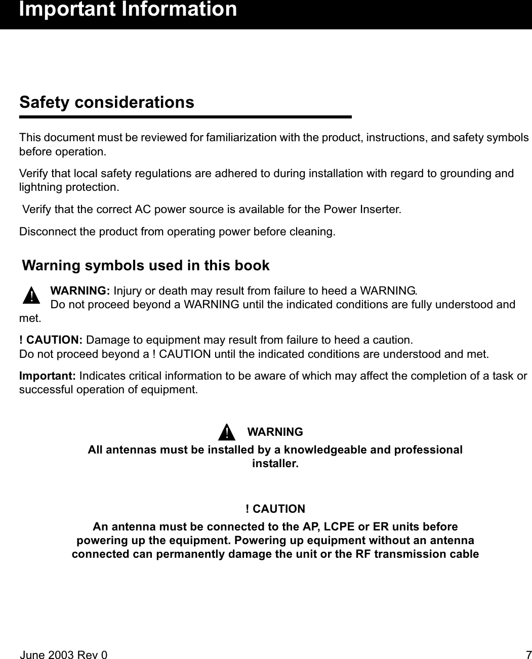
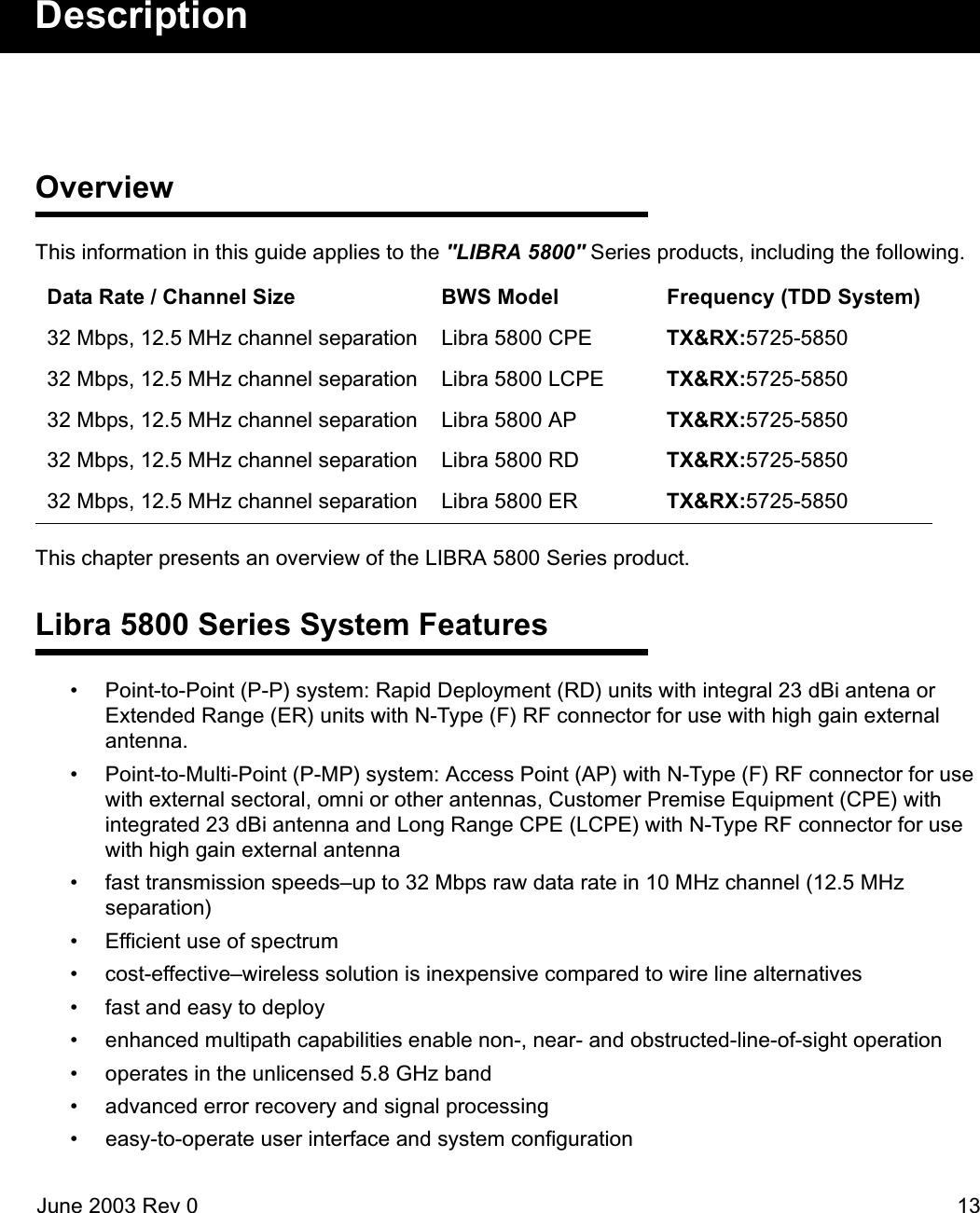
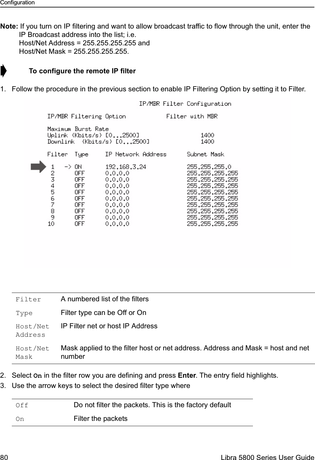
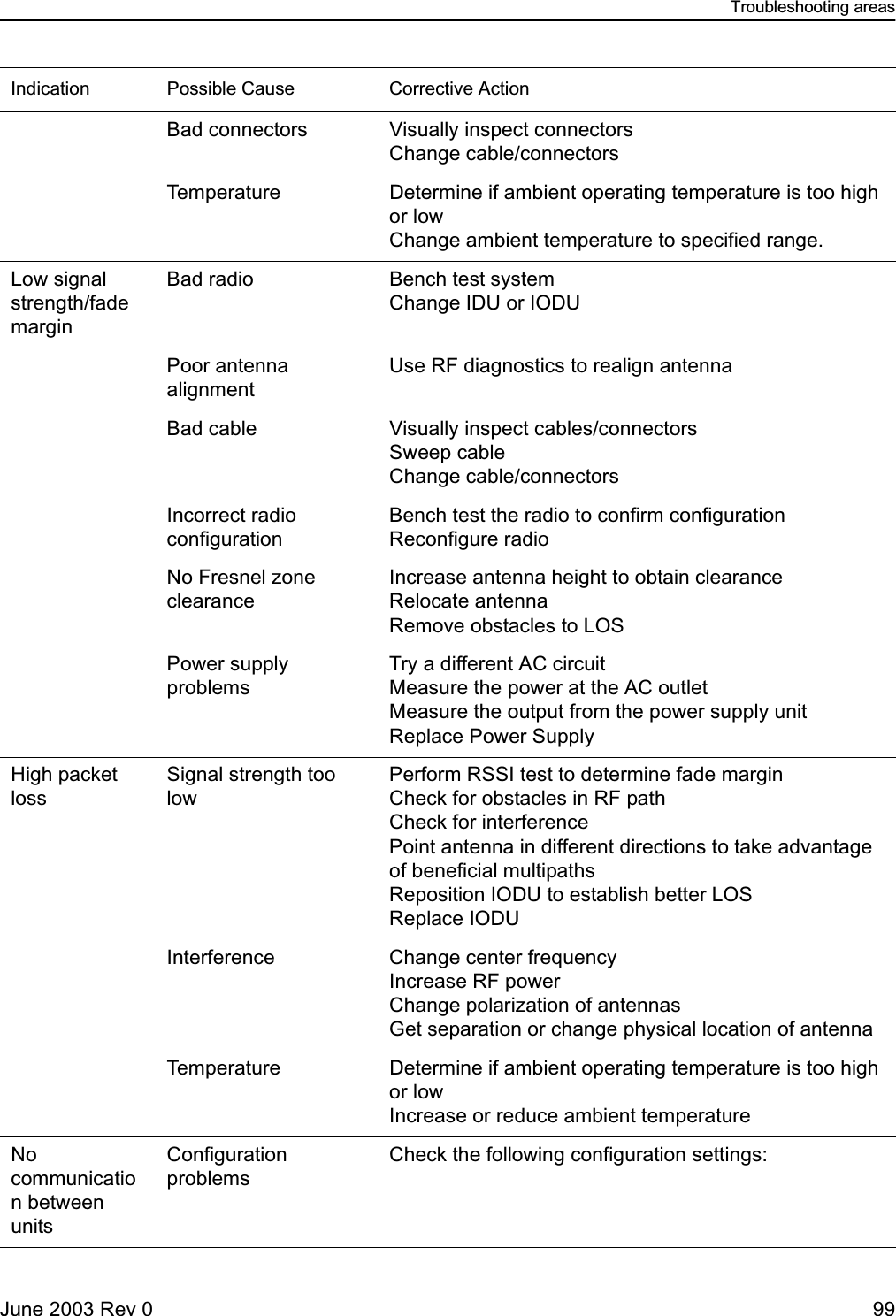
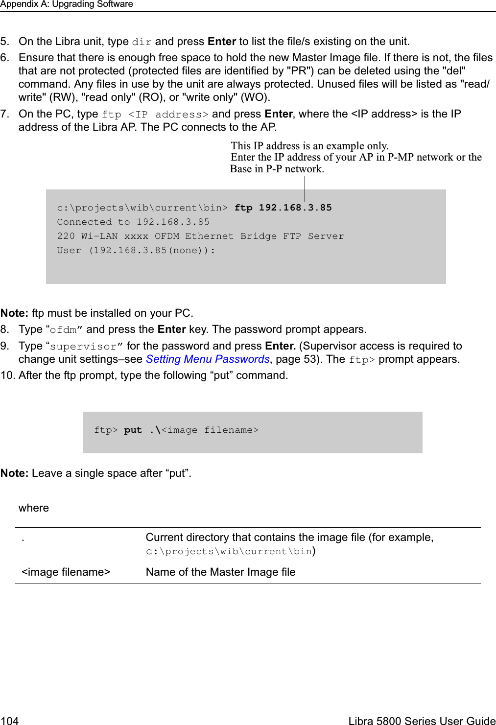
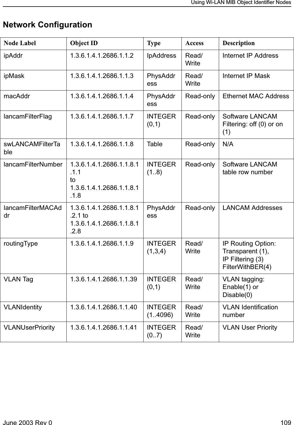
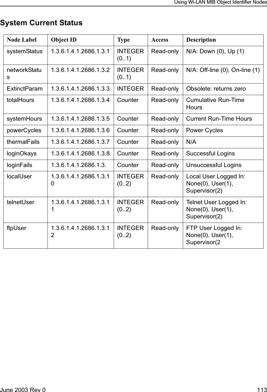
![Configuration70 Libra 5800 Series User GuideRadio ConfigurationYou can configure radio settings such as RF station IDs, Sector ID, Synchronization ID, center frequencies transmit power and Base Station modulation type with the Radio Configuration menu. Setting the RF Station ID (P-MP Only)Each AP, CPE or LCPE unit requires a unique RF Station ID to identify it on the network. Every unit must have a unique RF Station ID. No two units in a single sector (i.e. one controlled by a single AP) may have the same ID.➧ To set the RF station ID1. From the Main System Menu, select Radio Configuration and press Enter. The Radio Configuration menu appears.2. Select RF Station Id [1..2048] and press Enter. The entry field highlights.3. Type a unique number for the RF Station ID and press Enter. Zero is not a valid Station ID.4. Record the RF Station ID you have assigned to the unit.You will need to know this number when you configure the polling list on the Access Point. 5. Reboot the system to effect the changes. See Reboot Current Image, page 60. Radio Configuration OFDM Station Type Base Station RF Station Id [1..2047] -> 2 Sector Id [0..31] 1 Synchronization Id [0..1] 0 Base Station Tx Disable Center Freq (kHz) 5787000 Set Tx Power (dBm) [-3...17] 17 Modulation Type QAM 16 Note: Changes on this menu aside from Tx Power require that the unit be rebooted to take effect.](https://usermanual.wiki/Wi-Lan/EB05/User-Guide-359940-Page-70.png)
![Radio ConfigurationJune 2003 Rev 0 71Setting the Sector IDEach Libra unit can have a Sector ID to identify its AP within the cell on the network. This prevents Libra units from connecting to different APs which may have the same Center Frequency.➧ To set the Sector ID1. From the Main System Menu, select Radio Configuration and press Enter. The Radio Configuration menu appears.2. Select Sector Id [0..31] and press Enter. The entry field highlights.3. Type a unique number for the Sector ID and press Enter. Zero is not a valid Sector ID.4. Reboot the system to effect the changes. See Reboot Current Image, page 60. Radio Configuration OFDM Station Type Base Station RF Station Id [1..2047] -> 2 Sector Id [0..31] 1 Synchronization Id [0..1] 0 Base Station Tx Disable Center Freq (kHz) 5787000 Set Tx Power (dBm) [-3...17] 17 Modulation Type QAM 16 Note: Changes on this menu aside from Tx Power require that the unit be rebooted to take effect.](https://usermanual.wiki/Wi-Lan/EB05/User-Guide-359940-Page-71.png)
![Configuration72 Libra 5800 Series User GuideSetting the Synchronization IDBecause of OFDM’s superior multipath performance it is possible for the CPE to falsely synchronize on an AP from a different sector operating at the same frequency. In order to avoid this type of error, the APs and CPEs of each sector can have one of two possible OFDM synchronization patterns. These patterns are orthogonal, thus a CPE with a given Synchronization ID will never synch to an AP with the other synch. Every CPE in the sector must have the same Synchronization ID as the AP of that sector. ➧ To set the Synchronization ID1. From the Main System Menu, select Radio Configuration and press Enter. The Radio Configuration menu appears.2. Select Synchronization Id [0..1] and press Enter. The entry field highlights.3. Type a 0 or 1 to select the Synchronization ID and press Enter. Factory default is zero (0).4. Reboot the system to effect the changes. See Reboot Current Image, page 60.Setting the RF Center FrequencyLibra 5800 equipment uses Time Division Duplexing (TDD). In TDD, the units transmit and receive on the same frequency. They alternate in time to provide the duplexing capability. The frequency of these channels depend on the model of equipment used. Radio Configuration OFDM Station Type Base Station RF Station Id [1..2047] -> 2 Sector Id [0..31] 1 Synchronization Id [0..1] 0 Base Station Tx Disable Center Freq (kHz) 5787000 Set Tx Power (dBm) [-3...17] 17 Modulation Type QAM 16 Note: Changes on this menu aside from Tx Power require that the unit be rebooted to take effect.](https://usermanual.wiki/Wi-Lan/EB05/User-Guide-359940-Page-72.png)
![Radio ConfigurationJune 2003 Rev 0 73The center frequency is a frequency located in the middle of each set of transmit and receive channels and it defines the group of frequencies situated around it.➧ To set the RF Center Frequency1. Move the cursor to the Set RF Center Frequency field and press Enter. The entry field is highlighted.2. Enter the frequency value assigned to this unit in kHz and press enter to effect the changes. The unit does not require rebooting for this change to become effective. Radio Configuration OFDM Station Type Base Station RF Station Id [1..2047] -> 2 Sector Id [0..31] 1 Synchronization Id [0..1] 0 Base Station Tx Disable Center Freq (kHz) 5787000 Set Tx Power (dBm) [-3...17] 17 Modulation Type QAM 16 Note: Changes on this menu aside from Tx Power require that the unit be rebooted to take effect.](https://usermanual.wiki/Wi-Lan/EB05/User-Guide-359940-Page-73.png)
![Configuration74 Libra 5800 Series User GuideSetting Tx PowerThe transmitter power setting enables you to adjust the strength of the transmit signal sent from the Libra unit to the antenna. The range is -3 dBm to 17 dBm. ➧ To set the Tx power1. From the Main System Menu, select Radio Configuration and press Enter. The Radio Configuration menu appears.2. Select Set Tx Power and press Enter. The field highlights.3. Type in the signal strength. The new signal strength is applied. Radio Configuration OFDM Station Type Base Station RF Station Id [1..2047] -> 2 Sector Id [0..31] 1 Synchronization Id [0..1] 0 Base Station Tx Disable Center Freq (kHz) 5787000 Set Tx Power (dBm) [-3...17] 17 Modulation Type QAM 16 Note: Changes on this menu aside from Tx Power require that the unit be rebooted to take effect.](https://usermanual.wiki/Wi-Lan/EB05/User-Guide-359940-Page-74.png)
![Radio ConfigurationJune 2003 Rev 0 75Setting the Modulation TypeThe OFDM Modulation Type can be selected from among the following possible values: "QAM 16", "QPSK" and "BPSK". The selected type will be added to the next superframe transmitted.➧ To set the Modulation Type1. From the Main System Menu, select Radio Configuration and press Enter. The Radio Configuration menu appears.2. Select Modulation Type and press Enter. The field highlights.3. Use the up/down arrows to select the desired modulation type from the pull down list, and press enter again. This change requires a reboot to take effect. Radio Configuration OFDM Station Type Base Station RF Station Id [1..2047] -> 2 Sector Id [0..31] 1 Synchronization Id [0..1] 0 Base Station Tx Disable Center Freq (kHz) 5787000 Set Tx Power (dBm) [-3...17] 17 Modulation Type QAM 16 Note: Changes on this menu aside from Tx Power require that the unit be rebooted to take effect.](https://usermanual.wiki/Wi-Lan/EB05/User-Guide-359940-Page-75.png)
![Configuration82 Libra 5800 Series User Guide3. Use the up and down arrow keys to select the following option.4. Press Enter to select the option.5. Select the Uplink (Kbits/s) [0...2500]option to set the MBR from the CPE to the AP.6. Type in the MBR allowed for that CPE. Note: entering zero in that field means that maximum burst rate is NOT enforced for that CPE.Filter with MBRThis option will enforce filtering and enforce the maximum burst rate](https://usermanual.wiki/Wi-Lan/EB05/User-Guide-359940-Page-82.png)
![IP/MBR Filter ConfigurationJune 2003 Rev 0 837. Select the Downlink (Kbits/s) [0...2500]option to set the MBR from the AP to the CPE. 8. Type in the MBR allowed for that CPE. Note: entering zero in that field means that maximum burst rate is NOT enforced for that CPE.](https://usermanual.wiki/Wi-Lan/EB05/User-Guide-359940-Page-83.png)


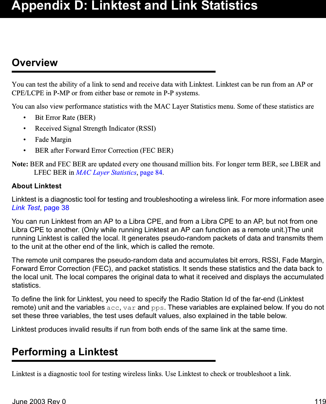
![Appendix D: Linktest and Link Statistics120 Libra 5800 Series User GuideThe transmitting (local) unit generates pseudo-random packets of data that it sends to the receiving (remote) unit at the other end of the link. The remote unit compares the packets and measures the BER (bit error rate), RSSI, Fade Margin, Forward Error Correction (FEC) and other statistics. It sends those statistics and the original data back to the local unit. The local unit reads the data and displays the accumulated statistics.Linktest can run from the base to any remote in a system, or from a remote to the base, but it cannot run from one remote to another. Linktest variablesYou can set four variables when starting Linktest. They are station ID of the remote, accuracy of the test, symbol variation and transmission speed.You must set the Radio Station ID. The system uses default values for the others if you do not set them. Before you start a Linktest, you must set the remote unit’s ID. See Setting the RF Station ID (P-MP Only), page 70 for information about viewing and setting station IDs.Note: Linktest will produce invalid results if run at the same time from both ends of the same link.➧ To run Linktest1. Connect a PC, Laptop or PDA with terminal emulation software to the serial port of the unit from which you will run Linktest. This can also be done via Telnet and TCP/IP. 2. Press the Esc key until you enter command line mode, as indicated by the wilan> prompt. 3. Type the following command line after the wilan> prompt.Linktest <station id of remote> [<acc> <var> <pps>]whereTIP: Linktest can run while the system carries user data, but the test overhead reduces the links data capac-ity. It is better to run Linktest while the system is idle.<station ID of remote>RF Station ID number of Linktest remote unit. This number is the Access Point of the system if Linktest is run from a CPE.<acc> Accuracy of the test, expressed as 1E<acc> bits. The default accuracy is 6 (1E6) or one million. The <acc> value defines the number of bits sent for each line of displayed statistics. Sending more bits produces more accurate statistics, but increases the time needed to run the test. The test sends 10 times as many bits as the acc value. Choosing an acc of 6, or 1 million, causes the test to send 1E7 bits, or 10 million.](https://usermanual.wiki/Wi-Lan/EB05/User-Guide-359940-Page-120.png)
![Testing the unitsJune 2003 Rev 0 129Testing the unitsTest the units to make sure that a basic RF link exists and data can be sent over it. In this section you will complete the following tasks.A) Test the link with LinktestB) Perform some simple network testsTesting the RF link with LinktestIn this step, you will test the basic RF link with Linktest. Linktest verifies that a link can send and receive test data.➧ To test the RF link with LinktestNOTE:In a lab environment the units are physically closely located. In order to avoid saturating the receivers make sure that the power setting is low enough. 1. Connect a PC to the serial port of the Libra Unit and access the Main System Menu.2. Log in using the supervisor password.3. Press Esc until the wilan> command line prompt appears.4. From the wilan> prompt type the following command.linktest <station Id of the unit to test to> [<acc> <pps>]where5. Press Enter. If the RF link has been configured properly the Linktest results appear.station IDRF Station ID of the Linktest remote unit. This can be the base station of the system if Linktest is run from another BWS unit.acc Accuracy of the test, expressed as 1E<acc> bits. The default is 6 (1E6), or one million bits. The acc value defines the number of bits sent for each line of displayed statistics. Sending more bits makes the statistics more accurate, but takes longer. The test sends 10 times the acc value. Choosing an acc value of 6 (one part in a million) causes the test to send 1E7 (10 million) bits.pps Transmission speed in packets per second (pps). The default is 60 packets per second. The lower the pps, the less bandwidth the Linktest takes up, and the less it affects any message data being sent at the same time. A higher pps value speeds up the test.](https://usermanual.wiki/Wi-Lan/EB05/User-Guide-359940-Page-129.png)
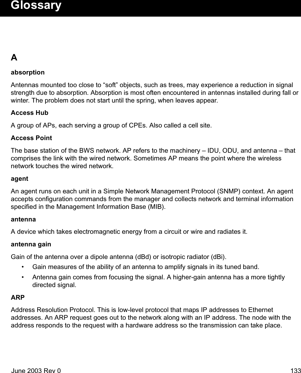

![June 2003 Rev 0 153System Revision Information Main System Menu Radio ConfigurationHardware Revision System Revision Information OFDM Station type (always Remote Unit)CPLD Revision System Software ROM Images RF Station ID (1-2048)DSP Revision System Current Status Sector ID (1..32)RF Board Model System Security Synchronization ID RF Board Serial Number System Commands Cycle Period (ms)Image File Name, Rev, Date, & Size Network Configuration Rx Center Frequency (kHz)RS and FE Version Radio Configuration Tx Center Frequency (kHz)BootROM Version IP/MBR Filter Configuration Set Tx Power (dBm) [-14 ... 17]MAC Layer Statistics Modulation TypeSystem Software ROM Images RF Statistics Default and Current Running Images Data Usage IP / MBR Filter ConfigurationSetup IP/MBR Filtering OptionSystem Current Status Maximum Burst RateCumulative Run-Time Uplink (Kbits/s) [0...2500]Current Run-time Logout Downlink (Kbits/s) [0...2500]Power Cycles Filter IP address & mask tableSuccessful LoginsUnsuccessful Logins Data Usage MAC Layer StatisticsLocal User Logged In Ethernet User Data Received View-onlyTelnet User Logged In Ethernet User Data Transmitted FTP User Logged In Setup (Quick Setup Menu)RF Board Attached RF Statistics (for Wi-LAN use) RF Station ID (1-2048)DSP & FPGA debugging info Sector ID (1..32)System Security Synchronization ID System Ethernet Access Network Configuration Rx Center Frequency (kHz)System Wireless Access Internet IP Address Tx Center Frequency (kHz)SNMP Public Community Name Internet IP Mask Set Tx Power (dBm) [-14 ... 17]SNMP Private Community Name Ethernet MAC Address Modulation TypeChange User Password VLAN Tagging Enable/Disable RSSI (dBm)Confirm User Password VLAN Id Null Depth (dB)Change Supervisor Password User Priority Fade Margin (dB)Confirm Supervisor Password Local Network Mac Filter RF Link StatusChange PDA Password Internet IP AddressConfirm PDA Password System Commands Internet IP MaskAuto Logout Timeout (Minutes) Set Default System Image System Ethernet AccessReboot Current Image Local Network Mac FilterReboot a System Image SNMP Private Community NameRestore Factory Configuration Passwords (Super, User, PDA)Restore Poweron Configuration Link Test TypeReset MAC Layer Statistics Start Link Test Menu Map](https://usermanual.wiki/Wi-Lan/EB05/User-Guide-359940-Page-153.png)