WiSilica SLM-D-B WC-D-2CH0010V User Manual WC D 2CH0010V rev4 3
WiSilica, Inc. WC-D-2CH0010V WC D 2CH0010V rev4 3
WiSilica >
User Manual
www.wisilica.com | 23282 Mill Creek Dr. #340, Laguna Hills, CA 92653, USA | +1 949 397 9330 |
info@wisilica.com
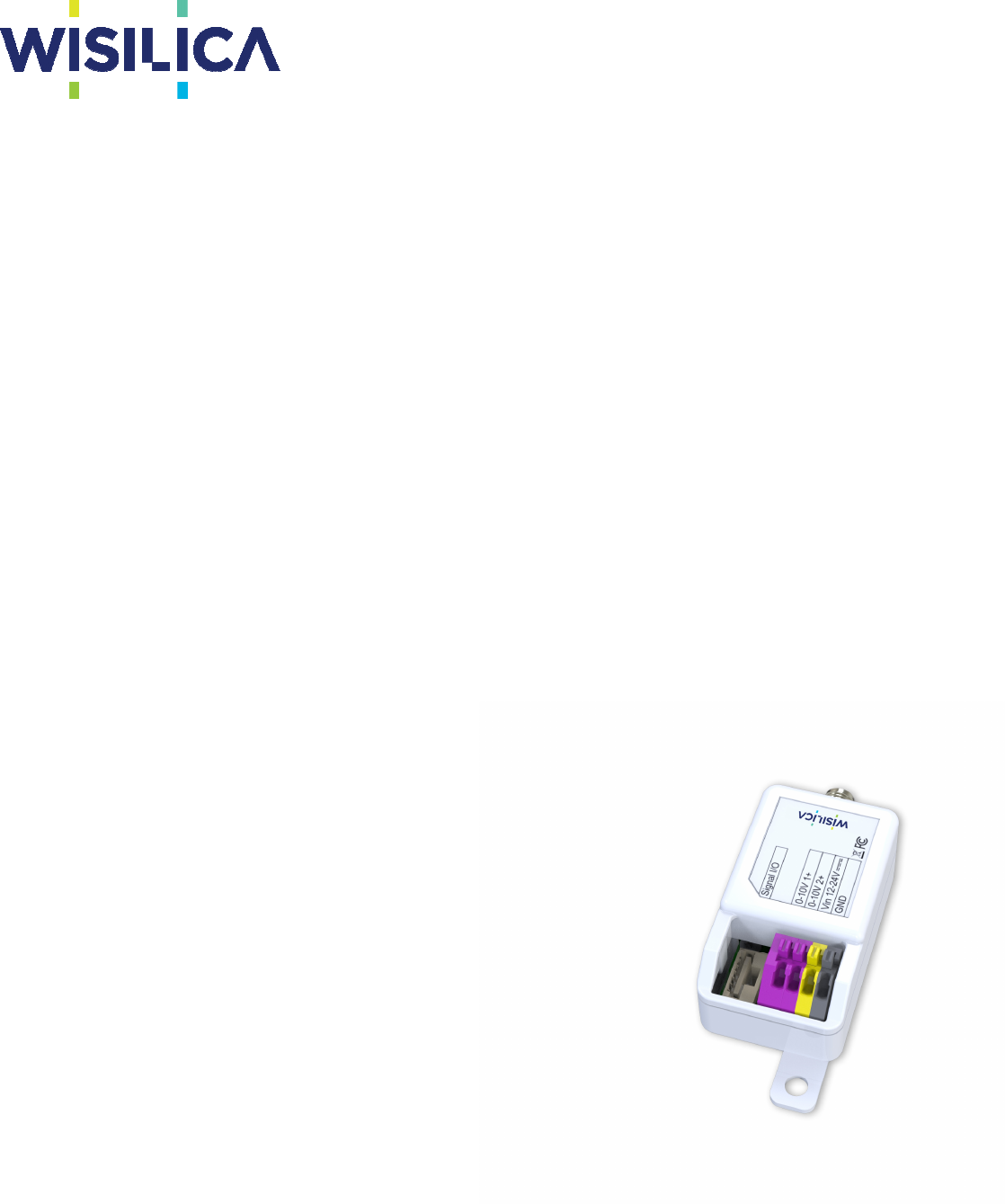
WC-D-2CH0010V
Wireless Controlled 0-10V Dual Channel Dimming Module
The WiSilica Energy Efficiency line of products are all Bluetooth Low Energy Mesh devices that can be
controlled or monitored via mobile device or cloud-based platform.
The 0-10V dimming module is powered by 12-24vdc from the auxiliary power of the LED driver and the 0-
10v dimming wires of the dimmable driver connect directly to the dimming module for dual channel
wireless dimming control.
WiSilica Mesh devices can be paired wireless with other WiSilica products like the integrated 4 in 1 micro-
sensor, wireless remote, occupancy sensors, ambient light sensors, real time clocks and more, giving the
building owner tremendous flexibility when optimizing their building to meet energy efficient standards or
guidelines.
The WiSilica Dim series not only controls lighting, it creates a smart mesh which also can be used to track
personnel, assets, patients, or anything that is equipped with or wearing a WiSilica BLE Tag. There are
tremendous possibilities when you think about security, workflow management, inventory management,
and whole building automation.
Specifications
Radio Frequency
(BLE 4.2) 2.4-2.5Ghz
Device Security
AES 128k Encryption with
3 level pairing keys (Network, APP, GUID)
Antenna
Integrated Antenna
SMA Connector for External Antenna
Technical Specifications
Operating: 0-70°c
Connector Type: Terminal Connection
Enclosure: ABS Plastic
Input Voltage: 12-24VDC
Input Frequency: 50/60Hz
Dim 1 & 2 Control Input: Push in style 18-24AWG
Dim Control Output: 0-10VDC
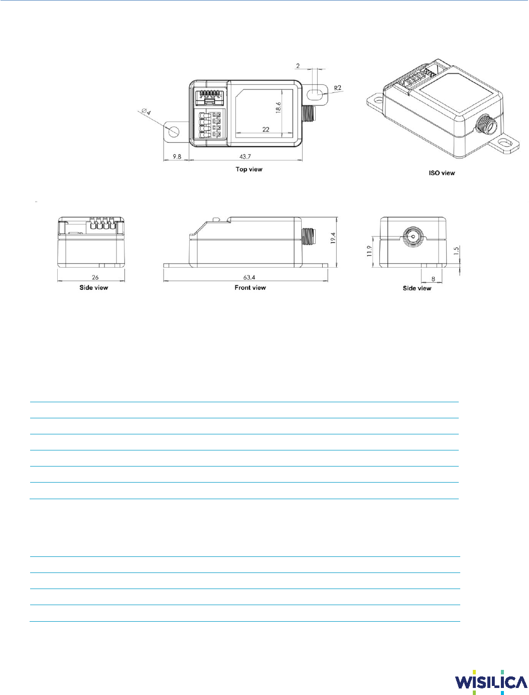
Dimensions: 63.4 x 26 x 19.4mm
WiSilica Network Lighting
| Control Series
www.wisilica.com | 23282 Mill Creek Dr. #340, Laguna Hills, CA 92653, USA | +1 949 397 9330 |
info@wisilica.com
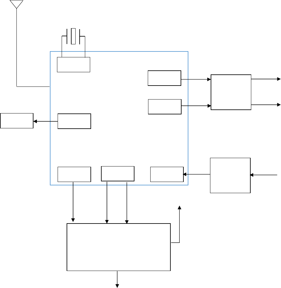
Block Diagram
BLE CHIP
PWM4
PWM5
POWER
UART
GPIO
OSC
Op-Amp
DC-DC
Converter
LED
Supply Input
12 to 24Vdc
26MHz
3V
0 to 10V
0 to 10V
2.4GHz
UWB Sensor interface
GPIO
3V
GND
DRV-IO UWB-INT
WC-D-2CH0010V WiSilica Network Lighting | Control Series
P3 Confidential and Proprietary to WiSilica, Inc.
Product Dimensions
Connector Details
Signal I/O Connector
PIN
SYMBOL
COLOR
DESCRIPTION
1
DRV
-
IO
Gray
External driver control (PWM or IO)
2
UWB
-
INTERRUPT
Yellow
Interrupt from UWB sensor
3
RX
Blue
UART
4
TX
White
UART
5
GND
Black
Power inpu
t for UWB sensor
(negative)
6
VDD33
Red
Power input for UWB sensor
(positive)
4 Pin Connector
PIN
SYMBOL
COLOR
DESCRIPTION
1
0
-
10V
1+
Purple
CH1 0 to 10V Analog dimming positive
2
0
-
10V
2+
Purple
CH2 0 to 10V Analog dimming positive
3
Vin 12
-
24V
Yellow
Input power supply positive
4
G
ND
Gr
a
y
Input power supply negative
WC-D-2CH0010V WiSilica Network Lighting | Control Series
P4 Confidential and Proprietary to WiSilica, Inc.
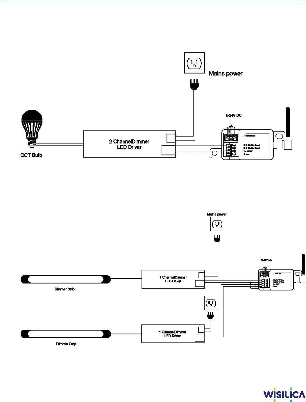
SLM-D Use cases
1. Controlling Single Dual Color Bulb
2. Controlling Twin Dual Color Dimmable tube

WC-D-2CH0010V WiSilica Network Lighting | Control Series
P5 Confidential and Proprietary to WiSilica, Inc.
User Precautions
Observe the correct polarity of output terminal.
Avoid input voltage exceeding the maximum rating, which may cause damage to the circuit
and result in malfunction.
Static electricity or surge voltage may damage the components inside LED Driver; in order
to avoid this please follow the proper anti-electrostatic working process.
FCC Statement
This equipment has been tested and found to comply with the limits for a Class B digital device,
pursuant to part 15 of the FCC Rules. These limits are designed to provide reasonable
protection against harmful interference in a residential installation. This equipment generates,
uses and can radiate radio frequency energy and, if not installed and used in accordance with
the instructions, may cause harmful interference to radio communications. However, there is no
guarantee that interference will not occur in a particular installation. If this equipment does
cause harmful interference to radio or television reception, which can be determined by turning
the equipment off and on, the user is encouraged to try to correct the interference by one or
more of the following measures:
• Reorient or relocate the receiving antenna.
• Increase the separation between the equipment and receiver.
• Connect the equipment into an outlet on a circuit different from that to which the receiver is
connected.
• Consult the dealer or an experienced radio/TV technician for help.
Caution: Any changes or modifications to this device not explicitly approved by manufacturer
could void your authority to operate this equipment.
This device complies with part 15 of the FCC Rules. Operation is subject to the following two
conditions: (1) This device may not cause harmful interference, and (2) this device must accept
any interference received, including interference that may cause undesired operation.
RF Exposure Information
To comply with FCC RF exposure compliance requirements,this grant isapplicable to only mobile
configurations. The antennas used for this transmittermust be installed to provide a separation
distance of at least 20 cm from allpersons and must not be co-l ocated or operating in conjunction
with any otherantenna or transmitter.