WiSilica WB10PE Linkit BLE-WiFi Gateway User Manual users manual
WiSilica, Inc. Linkit BLE-WiFi Gateway users manual
WiSilica >
users manual

FCC_Configuration Procedures for iOS App
COPYRIGHTCopyright © 2015 WiSilica, Inc. All Rights Reserved. FCC ID: 2AG4NWB10PE
No part of this publication may be reproduced, transmitted, transcribed, stored in a retrieval system,
or translated into any language in any form or by any means without the written permission of
WiSilica, Inc.
TRADEMARKS
WiSeHome, WiSe, WiSe Mesh, WiSe Tech, WiSeApp, WiDe, WiBe, WiSe Connect are
trademarks of WiSilica, Inc. and/or its affiliates in the US and/or other countries. WiSilica Green in
connection with IOT is distinctive of WiSilica brand products. All other registered and unregistered
trademarks herein are the sole property of their respective owners.
LICENSE INFORMATION
License Agreement
WiSeConnect Linkit Bridge Technical Specification
General Information
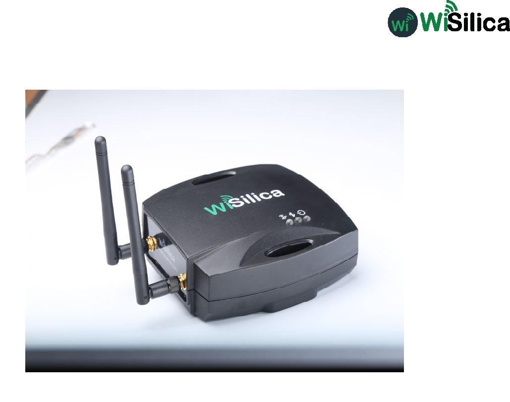
The WiseMesh BLE to WiFi Gatewaty (GW) is a fully integrated GW that provides Internet
connectivity to the WiseMesh BLE mesh network. These GWs can be seamlessly integrated with any
enterprise WLAN deployment or Ethernet LAN, providing the connectivity to all of the components
within the WiSeMesh network, including: eners, repeeaters,tags and other devices enabled through
the WiSilica BLE modules.
Multiple WiseMesh GWs can be installed within a WiSeMesh network deployment and the number
of GWs is determined by the application. As an example, a large scale Real-time location services
application will require more GWs and internet capacity than a small scale connected lighting
application.
Figure 1 WiFi-BLE Linkit Bridge
Key Features
Power Supply Options
The WiSeMesh BLE/WiFi GW supports both Power over the Ethernet (PoE) and Mini USB power
options for flexibility and ease of installation.
Dual Communication and Security
Each WiSeMesh BLE/WiFi GW can send and receive data in real time from the BLE connected devices
within the mesh to and from the WiSilica cloud. Each WiSeMesh BLE/WiFi GW is AES 128k encrypted
for device and network security.
WiFi Configuration
The WiseMesh BLE/WiFi GW is configured through a mobile application based user interface for WiFi
configuration.
within the WiSeMesh network, including:smth, eners, repewithin the WiSeMesh network,including:listener, repe

WiSeConnect Linkit Bridge Technical Specification
Specifications
Radio Frequency
(BLE 4.0) 2.4-2.48 Ghz
Wireless Standard Supported
WiFi (IEEE 802.11 11b/g) Bluetooth 4.1 Stack WiFI Data Rate up to 72.2 Mbps
WiFi Security
WAP-2
Device Security
AES 128k Encrypted,
With 3 Level Pairing Keys (Network, App, GUID)
Integrated Antenna
Integrated Antenna,
WiFi – 18dBm
BLE- 2.4GHz ~ 2.5GHz 2dBi
External Antenna
Omni Directional Antenna 2 x 50 ohms SMA connectors:
1/2 wave whip
WiFi BLE
Power
Mini USB or PoE (48Vdc)
Physical interfaces
Mini USB, Ethernet with PoE (RJ485)
Dimensions
129 X 130 X 46mm
Operating Conditions
Temp 0-50°c
WiFi – 14dBm
(The device must be professionally installed)
Table of Contents
Table of Contents............................................................................................................................ 3
Table of figures ............................................................................................................................... 4
1 Home screen .............................................................................................................................. 5
2 Sign up ..................................................................................................................................... 5
3 Sign In ...................................................................................................................................... 6
4 Organization management ........................................................................................................... 6
5 User Management ...................................................................................................................... 8
6 Device Commissioning ............................................................................................................. 11
7 How to enable listener............................................................................................................... 15
8 Bridge Commissioning.............................................................................................................. 16
8.1 Bridge Commissioning via Wi-Fi ........................................................................................ 16
8.2 Bridge Commissioning via Ethernet ................................................................................ 18
8.3 Bridge Commissioning via P.O.E ........................................................................................ 18
9 How to run Bridge Diagnostics .................................................................................................. 18
Table of figures
Figure 1 Sign Up ............................................................................................................................. 5
Figure 2 Sign In .............................................................................................................................. 6
Figure 3 My Organizations .............................................................................................................. 6
Figure 4 Click "Create (+) "option .................................................................................................... 7
Figure 5 Success message ............................................................................................................. 7
Figure 6 Users ................................................................................................................................ 8
Figure 7 Click "Create (+) " option ................................................................................................... 8
Figure 8 Select User role ................................................................................................................ 9
Figure 9Enter user details ............................................................................................................... 9
Figure 10 Select organization ....................................................................................................... 10
Figure 11 Review the details ......................................................................................................... 10
Figure 12 Success message ......................................................................................................... 11
Figure 13 "Add device" option ....................................................................................................... 11
Figure 14 Select organization ....................................................................................................... 12
Figure 15 Set a filter ...................................................................................................................... 12
Figure 16 Scan for devices ........................................................................................................... 13
Figure 17 Scanned device ............................................................................................................ 13
Figure 18Pair the beacon tag ........................................................................................................ 14
Figure 19 Pair the listener ............................................................................................................. 14
Figure 20 Paired device in dashboard ........................................................................................... 15
Figure 21 Listener Enable ............................................................................................................. 15
Figure 22 Scan bridge device........................................................................................................ 16
Figure 23 Pair bridge device ......................................................................................................... 17
Figure 24 Bridge device under default group ................................................................................. 17
Figure 25 Bridge commissioning via ethernet ................................................................................ 18
Figure 26 Status check ................................................................................................................. 19
Figure 27 Bridge diagnostics ......................................................................................................... 19
Overview
WiSe IOT Platform provides end to end user experience providing plug and play hardware for
devices and bridges, and software modules for devices, bridges, apps and cloud. Manufactures,
integrators, distributors, data scientists, application developers, executive management and end
users can directly benefit from deploying and/or integrating with one or more components of the
WiSe platform. WiSe IOT platform combines its innovative WiSe Mesh technology with plug and
play modules to get a devices networked in minutes without any additional hardware. This
document addresses the architecture of WiSe Platform and its components.
Hardware Versions Used
Sl#
Device
Firmware
1
Wise Beacon
1.3.27
2
Wise Mesh Listener
1.3.72
3
Wise Bridge Device
2.1.19
1 Home screen
When the application is launched, user will be welcomed by a screen containing four buttons.
1. Forgot Password
2. Sign In
3. Sign Up
4. Skip Sign In
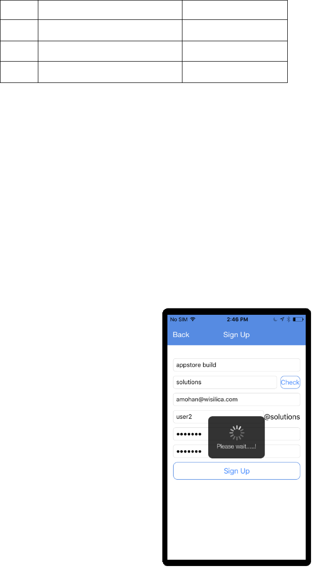
2 Sign up
a) Click “Sign Up” button in home screen
b) Enter valid information in all the fields.
c) Click “Sign Up”
On a successful sign up, a new account is created.
Figure 1 Sign Up
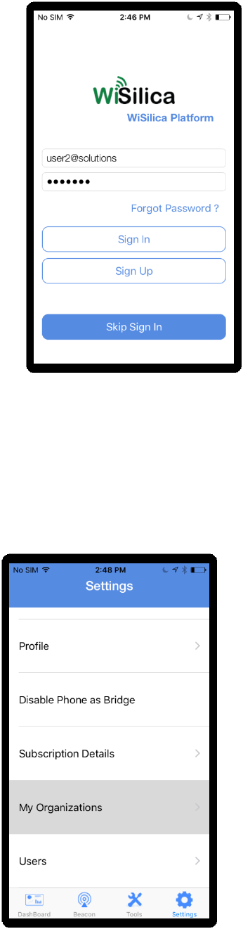
3 Sign In
a) Enter valid credentials i.e username and password.
b) Click “Sign In”
Figure 2 Sign In
4 Organization management
a) Select “My Organizations” option under “Settings” tab.
Figure 3 My Organizations
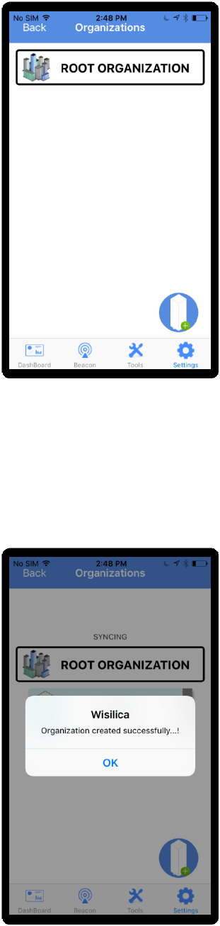
b) Click on “Create (+)” option.
Figure 4 Click "Create (+) "option
c) Enter organization name and click “Finish”
Figure 5 Success message
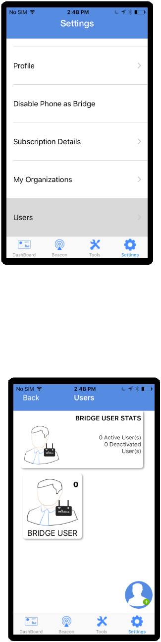
5 User Management
a) Select “Users” option under “Settings” tab.
Figure 6 Users
b) Click on “Create (+) ” option.
Figure 7 Click "Create (+) " option
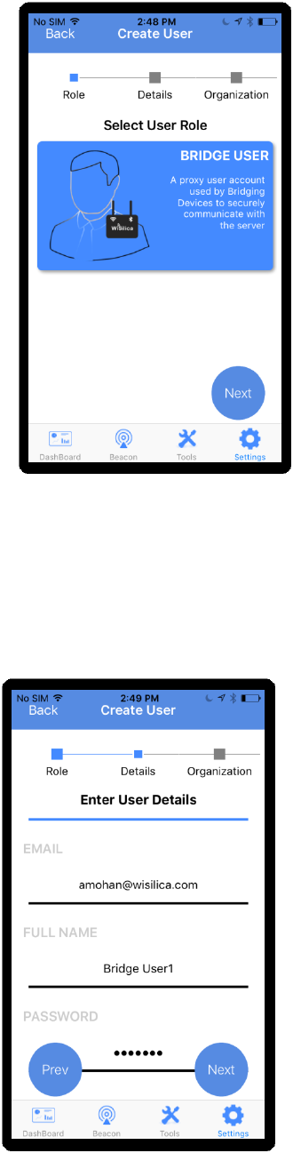
c) Select User role and click on “Next” button.
Figure 8 Select User role
d) Enter user details and click “Next” button.
Figure 9Enter user details
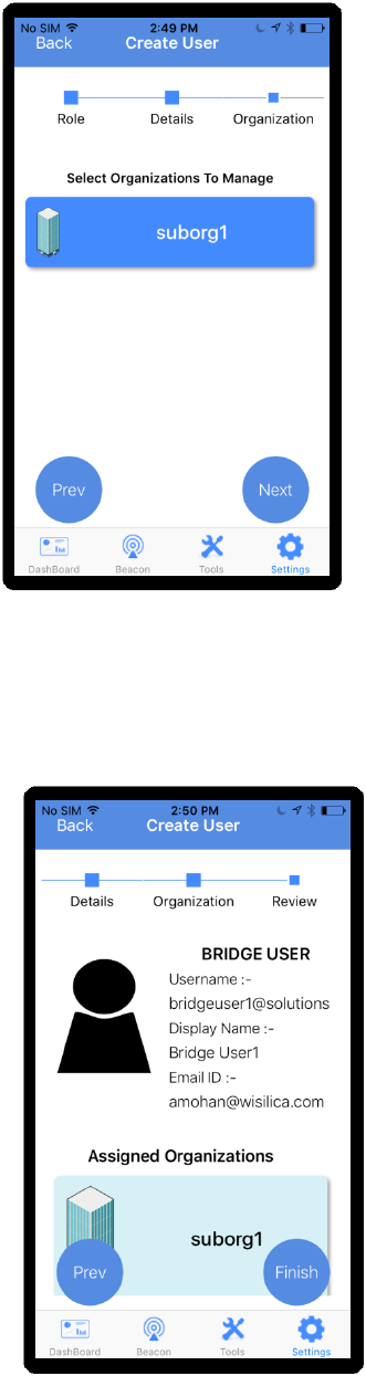
e) Select organizations to manage.
Figure 10 Select organization
f) Review the entered details and click on “Finish”.
Figure 11 Review the details
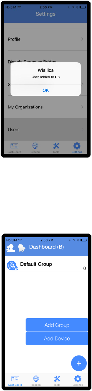
g) Click on “OK” button to complete user creation.
Figure 12 Success message
6 Device Commissioning
Device Commissioning is the process of scanning and assigning devices to the groups.
a) Click on “(+)” and select “Add Device” from the main menu options.
Figure 13 "Add device" option
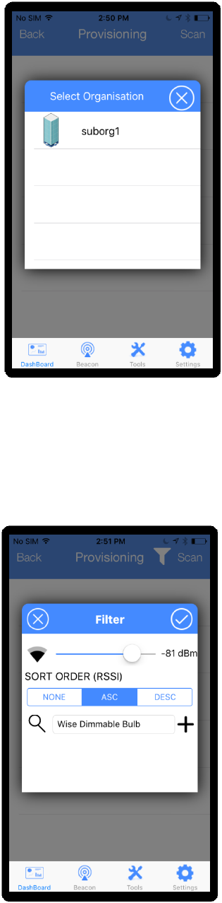
b) Select the organization under which the device is to be commissioned.
Figure 14 Select organization
c) Click on filter icon if the user wants to filter out a particular type of device that needs to be
scanned for in the presence of multiple device types.(OPTIONAL)
Figure 15 Set a filter
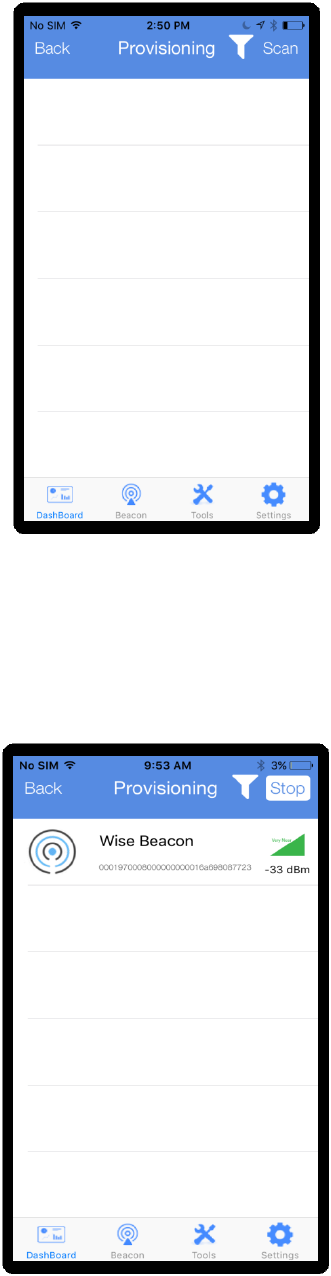
d) Click on “Scan”
Figure 16 Scan for devices
e) When the Wise Beacon appears on scanned list, swipe leftwards.
Figure 17 Scanned device
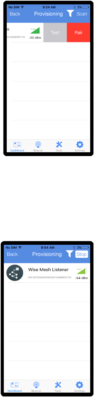
f) Click on “Pair” button .
Figure 18Pair the beacon tag
g) Scan for Wise Mesh Listener and pair the device in a similar manner.
Figure 19 Pair the listener
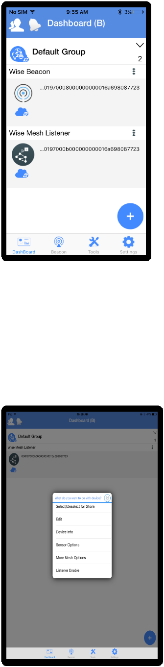
h) Paired devices will appear in the dashboard.
Figure 20 Paired device in dashboard
7 How to enable listener
Click on optional menu in the right end of the paired listener.
Select “Listener Enable”
Figure 21 Listener Enable
8 Bridge Commissioning
Creating a bridge user prior to commissioning a bridge device is mandatory. Please refer
heading number 5, “USER CREATION” to create a bridge user and then proceed as follows.
Bridge device has to be commissioned to perform a remote operation.
8.1 Bridge Commissioning via Wi-Fi
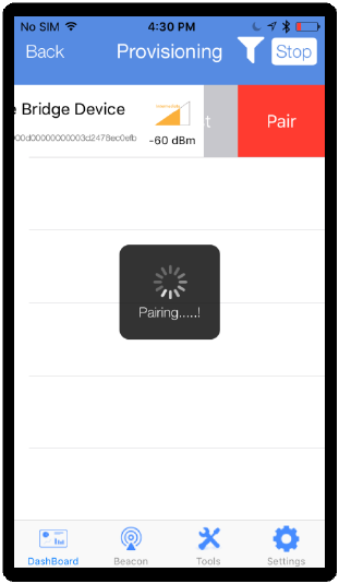
a) In order to pair a bridge device, follow steps 6(a) to (d).
Figure 22 Scan bridge device
b) Enter the credentials as follows:
Check the option, Bridge Listener Enabled.
Select the encryption type.
Enter SSID and password.
Place the cursor in the username field and select a bridge user from the list of created
bridge users.
Enter password of the selected bridge user.
Click on “Pair” to get the device paired.
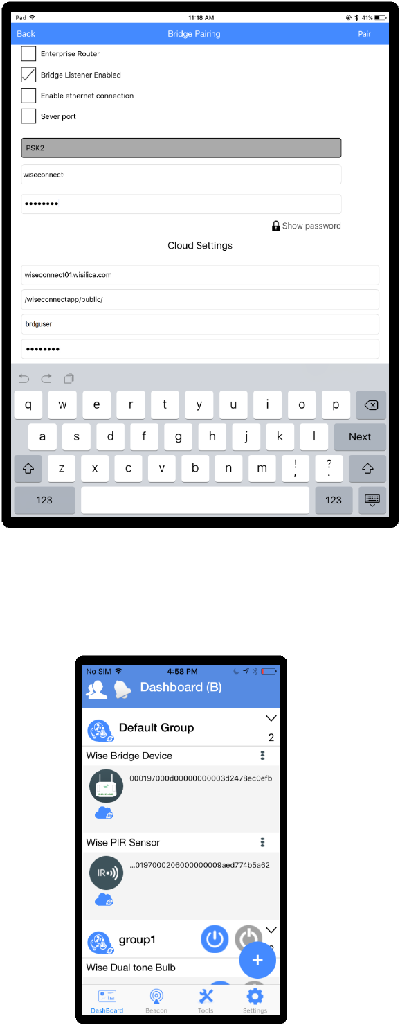
Figure 23 Pair bridge device
c) Paired bridge can be seen in the dashboard under default group.
Figure 24 Bridge device under default group
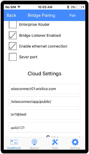
8.2 Bridge Commissioning via Ethernet
Check the options , Bridge Listener Enabled and Enable Ethernet connection.
Place the cursor in the username field and select a bridge user from the list of created bridge
users.
Enter password of the selected bridge user.
Figure 25 Bridge commissioning via Ethernet
8.3 Bridge Commissioning via P.O.E
Note : The procedure is same as in 7.2. The only difference is that the power is provided to the
bridge via Ethernet cable and hence we need not connect the power cable.
9 How to run Bridge Diagnostics
Bridge diagnostics can be used to know the present operational condition of the bridge device.
a) Select optional menu in the right end of bridge name and select “Status check”.
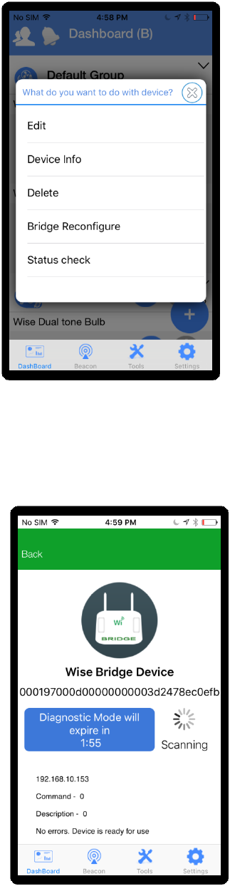
Figure 26 Status check
b) Bridge enters diagnostic mode and details of the bridge can be seen here.
Figure 27 Bridge diagnostics

FCC statement
This device complies with Part 15 of the FCC Rules: Operation is subject to
the following two conditions:
1. This device may not cause harmful interference and
2. This device must accept any interference that is received, including any interfer
ence that may cause undesired operation.
Human exposure to RF emissions from mobile devices (47 CFR ¡ì2.1091) may be
evaluated based on the MPE limits adopted by the FCC for electric and magnetic
field strength and/or power density, as appropriate, since exposures are assumed
to occur at distances of 20 cm or more from persons.
This device is acting as slave and operating in the 2.4 GHz (2412 ~2462 MHz&
2402 -2480 MHz) band.
Ad Hoc function is supported but not able to operate on non-US frequencies.
Do not use the device with the environment which below minimum -10 ℃ or maximum
over 50℃ .
NOTE: This equipment has been tested and found to comply with the limits for
a Class B digital device, pursuant to part 15 of the FCC Rules. These limits are
designed to provide reasonable protection against harmful interference in a
residential installation. This equipment generates uses and can radiate radio
frequency energy and, if not installed and used in accordance with the
instructions, may cause harmful interference to radio communications.
However, there is no guarantee that interference will not occur in a particular
installation. If this equipment does cause harmful interference to radio or
television reception, which can be determined by turning the equipment off and
on, the user is encouraged to try to correct the interference by one or more of
the following measures:
- Reorient or relocate the receiving antenna.
- Increase the separation between the equipment and receiver.
-Connect the equipment into an outlet on a circuit different from that to which
the receiver is connected.
-Consult the dealer or an experienced radio/TV technician for help
Changes or modifications to this unit not expressly approved by the party responsible for compliance
could void the user's authority to operate the equipment.
RF Exposure Information
This equipment complies with FCC radiation exposure limits set forth for an uncontrolled environment
nd can be used/operated in portable operating conditions without any restrictions.In order to avoid
the possibility of exceeding the FCC radio frequency exposure limits, human proximity to the antenna
shall not be less than 20cm during normal operation.
and can be used/operated in mobile operating conditions without any restrictions.In order to avoid
Changes or modifications to this unit not expressly approved by the party responsible for compliance
could void the user's authority to operate the equipment.