Wiimu Information Technology A28 Shenzhen SEM User Manual 15 A28 UserMan
Wiimu Information Technology Inc. Shenzhen SEM 15 A28 UserMan
15_A28 UserMan.pdf
LinkPlay Wireless Smart Audio
Module (A28)
User Manual
Rev 1.0
SEP. 21, 2015

DocTitle Wirelesssmartaudiomodule Number WMB20150921
Version 1.0
Document No.: WMB20150921 Page 2 of 20
HISTORY
Version Date Description Author
0.1 09/21/2015 Initialdocument

DocTitle Wirelesssmartaudiomodule Number WMB20150921
Version 1.0
Document No.: WMB20150921 Page 3 of 20
INDEX
Features ....................................................................................................................................................................... 4
1. Overview ............................................................................................................................................................. 5
1.1.Parameters................................................................................................................................................ 5
2.Hardware Description ............................................................................................................................... 6
2.1.Description of hardware interface ............................................................................................................ 6
2.2.Mechanical dimension ............................................................................................................................. 9
2.3.Connect with Audio Codec ...................................................................................................................... 9
2.4.External antenna .................................................................................................................................... 11
2.5.10/100M Ethernet Port .......................................................................................................................... 11
2.5.1.Connect the module with RJ45 .......................................................................................................... 12
2.6.USB host port ........................................................................................................................................ 12
2.7.Power supply ......................................................................................................................................... 13
3.Software .................................................................................................................................................... 13
3.1.Airplay introduction ............................................................................................................................... 14
3.2.DLNA introduction ................................................................................................................................ 14
3.3.WiFi mode ............................................................................................................................................. 15
3.3.1.AP Client mode ........................................................................................................................ 15
3.4.Web Server setup ................................................................................................................................... 15
3.4.1.Web server login ..................................................................................................................... 16
3.4.2.Connecting the module to another AP ................................................................................. 16
3.4.3.Advanced setting for the module .......................................................................................... 18
3.4.3.1.Module setting page .............................................................................................................. 18
3.4.3.1.1.Software upgrade ............................................................................................................... 18
3.5.Use UART to debug ............................................................................................................................... 19
3.6.WPS Setting ........................................................................................................................................... 20
3.7.Restore to factory setting ....................................................................................................................... 20

DocTitle Wirelesssmartaudiomodule Number WMB20150921
Version 1.0
Document No.: WMB20150921 Page 4 of 20
Features
Support 2.4GHz 802.11 b/g/n with highly optimized Wi-Fi performance
Support 10/100Mbps Ethernet
Support Internet audio streaming via Apple AirPlay or DLNA
Support Spotify, Pandora, iHeartRadio, Tidal, Tune in and many more ...
Support TCP/IP/UDP/HTTP/UPNP protocol
Support play-list with M3U, M3U8, WPL, ASX, PLS formats
Support MP3/WMA/AAC/AAC+/ALAC/FLAC/APE/WAV etc. audio formats
Support STA/AP/AP Client mode
Support Ethernet, UART and USB2.0 interfaces
Support digital audio input and output via I2S interface
Built-in web server to easily configure the module
Support remote control of module via WLAN
Support online firmware upgrade
Support module configuration via iOS or Android APP
Support Wi-Fi UART pass-through or self-defined MCU/UART interface
Support multi-room audio (a.k.a, party mode) and multi-channel audio with perfect time synchronization
among speakers
Support most popular streaming services around the world
Provide iOS, Android and PC SDK and applications to work with the module
Applications
Wi-Fi speaker
Smart toy
Smart audio receiver
Wi-Fi audio docking station for smartphones
Internet smart audio device
Internet radio receiver
Home automation and Internet of Thing (IoT)

DocTitle Wirelesssmartaudiomodule Number WMB20150921
Version 1.0
Document No.: WMB20150921 Page 5 of 20
1.Overview
LinkPlay Wi-Fi Audio module A28, is our second generation smart audio modules developed to be used in
wireless speaker, wireless docking station, Wi-Fi base station, home automation and smart toy. It supports
802.11b/g/n standard with up to 300Mbps bandwidth. It could work at AP, AP client or station modes. It is fully
compatible with Apple AirPlay and digital living network alliance (DLNA) streaming standards. It supports Hi-Fi
audio up to 192KHz, 24-bit with most popular audio formats. It supports multi-room and multi-channel audio
streaming with perfect synchronization.
With this module, you can play the music on your speaker wirelessly from iPhone, iPad , iPod touch, Android
devices or PC. More important, it enables the traditional speaker system to become the Internet enabled device
through the wired or wireless connection provided by the module. Thus, you could freely playback any Internet
audio contents such as music, podcast, radio or either the accompany audio in the movie directly from the Internet.
1.1. Parameters
Items Performance
Wireless
Certification FCC/CE/Reach/RoHS
Standard 802.11 b/g/n 2T2R
Frequency 2.412GHz-2.484GHz
Transmit
802.11b: +20dBm(Max.)
802.11g: +18dBm(Max.)
802.11n: +15dBm(Max.)
Receive sensitivity
802.11b: -89dBm
802.11g: -81dBm
802.11n: -71dBm
Antenna options External:I-PEX
Hardware
Work voltage 3.5V ~ 5.5V
Work current 130 mA ~ 320 mA
Peak current 320 mA
Standby current 20 mA
Work temperature -25℃ - 85℃
Storage temperature -40℃ - 135℃
Status LED AP status, client status, power, WiFi data transfer
I2S input/output 24 bit, up to 192KHz
Wi-Fi distance 110m
IO extension Ethernet, USB, UART, GPIO, I2C
Size 28.5mm X 42mm X 3mm, 37-pin DIP
Software
Wi-Fi working mode AP Client (by default)/AP/STA

DocTitle Wirelesssmartaudiomodule Number WMB20150921
Version 1.0
Document No.: WMB20150921 Page 6 of 20
Security WEP/WPA-PSK/WPA2-PSK/WAPI
Encryption WEP64/WEP128/TKIP/AES
User Configuration Web browser, Companion APP
Software update Web browser or APP
Online update Support
Audio source U disk, Smartphone/Tablet/PC, online contents
Applications support iOS, Android, Win7/8
Audio streaming
protocol
AirPlay
DLNA, Spotify Connect, QQ music Qplay
Multi-room audio Support Airplay, Spotify Connect, DLNA, U Disk attached to
WiFi device, BT and Aux-in multi-room transmission
Table1-1 LinkPlay A28 module parameters
2. Hardware Description
2.1. Description of hardware interface
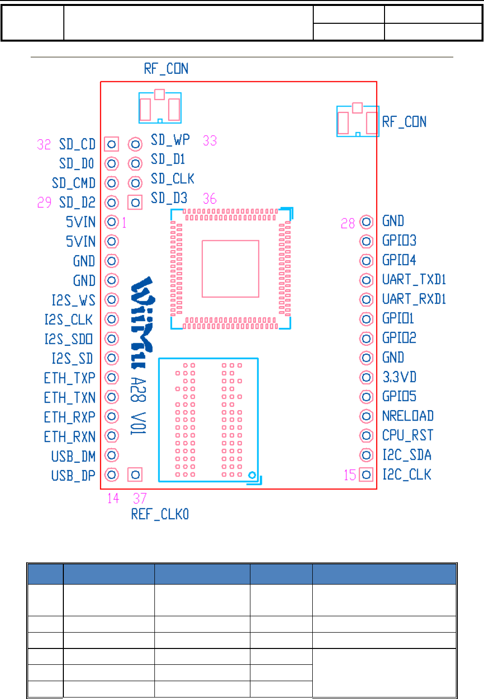
A28 module provides the option to connect with customer board through its 37-pins DIP . The detail is as follows.
DocTitle Wirelesssmartaudiomodule Number WMB20150921
Version 1.0
Document No.: WMB20150921 Page 7 of 20
Figure 2-1 A28 interface pins
Pin description:
Pin Description Net Type Comments
3,4,21
,28
GND GND Power Ground
1,2 5VD input DC+5V Power, I +5V@ 350mA
20 3.3VD output DC+3.3V Power, O Output +3.3V@100mA
5 I2S_WS I2S_WS O All pins could be pin shared as
GPIO
6 I2S_CLK I2S_CLK I/O
7 I2S_SDO I2S_SDO O

DocTitle Wirelesssmartaudiomodule Number WMB20150921
Version 1.0
Document No.: WMB20150921 Page 8 of 20
8 I2S_SDI I2S_SDI I
9 ETH_TXP ETH_TXP O 10M/100M Ethernet interface
(Current driven)
10 ETH_TXN ETH_TXN O
11 ETH_RXP ETH_RXP I
12 ETH_RXN ETH_RXN I
13 USB_DM USB_DM I/O USB 2.0 host
14 USB_DP USB_DP I/O
15 I2C_CLK I2C_CLK O I2C interface, in module 4.7K
resistor pull-up
16 I2C_SDA I2C_SDA I/O
17 Module reset CPU_RST I,IPU Reset with pull down, reset
time >300ms
18
Restore factory
setting nReload I/O, IPU
First Input 0 and keep for more
than 5 seconds then change to 1,
it will go back to factory setting,
in module 4.7K resistor pull-up
19 GPIO GPIO5 I/O, IPU in module 4.7K resistor pull-up
22 GPIO GPIO2 I/O, IPU in module 4.7K resistor pull-up
23 GPIO GPIO1 I/O, IPU in module 4.7K resistor pull-up
24 UART receive UART_RXD I, Need keep UART_TXD high
during chip boot-up
25 UART transmit UART_TXD O, IPU
26 GPIO GPIO4 I/O, IPU
27 GPIO GPIO3 I/O,IPU
37 Reference CLK REF_CLK O,IPD Reference Clock Output
29 SDIO Data SD_D2 I/O SDIO, GPIO 10K Pull-up
30 SDIO CMD SD_CMD O SDIO CMD, GPIO, 10K IPU
31 SDIO Data SD_D0 I/O SDIO Data0, GPIO,10K IPU
32 SDIO Detect SD_CD I SDIO detect,GPIO, 10K IPU
33 SDIO WP SD_WP I
Write Protect, GPIO, 10K IPU,
If MICRO SD (TF), need put
this pin to GND
34 SDIO Data SD_D1 I/O SDIO Data 1, GPIO, 10K IPU
35 SDIO CLK SD_CLK O SDIO CLK, GPIO
36 SDIO Data SD_D3 I/O SDIO Data 3, GPIO, 10K IPU
Table 2-1 LinkPlay A28 module pin description
Notes:
1. I: Input, O: Output, P: Power, IPU: Internal Pull Up, IPD: Internal Pull Down, A: Analog.
DocTitle Wirelesssmartaudiomodule Number WMB20150921
Version 1.0
Document No.: WMB20150921 Page 9 of 20
2.2. Mechanical dimension
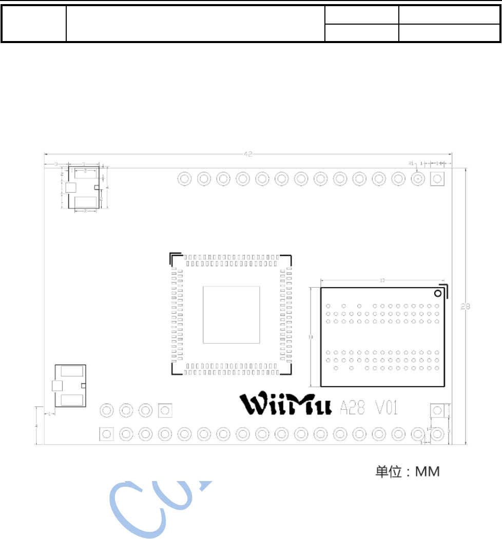
LinkPlay A28 module has the physical dimension of 28.5 x 42mm. The detailed layout shows below. The unit is in
mm.
Figure 2-2: LinkPlay A28 physical dimension
2.3. Connect with Audio Codec
LinkPlay A28 module has digital audio interface I2S. It supports both master and slave modes.
- Master mode:
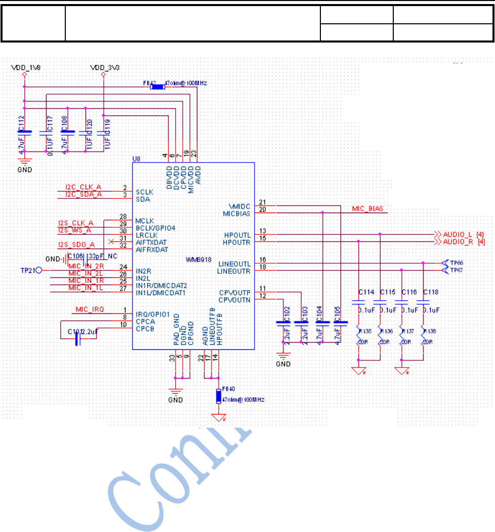
In master mode, it is recommended to connect with an audio codec IC for audio playback and record shown in the
following example. Current module firmware supports Wolfson WM8918/WM8960. The reference schematics is
shown below.
DocTitle Wirelesssmartaudiomodule Number WMB20150921
Version 1.0
Document No.: WMB20150921 Page 10 of 20
Table 2-3 Connect with external audio IC with A28 module
Notes:
Please see the following documents for details:
WIFIAudio_Module_Design_Note_V03.pdf
WIFIAudio A28A31 Reference Design_4.pdf
- Slave mode:
When A28 module is working as I2S slave mode, it needs the external input for both I2S_WS and I2S_CLK.
Here we use the MVSilicon’s MCU/Codec chip AP8048/AP8064 as an example to explain how to connect the
module as the I2S slave. The connection method and function description are as follows:
1) Case 1: Wi-Fi, BT or AUX IN can be connected to AP8048/8064 directly. The AP8048 etc. will decide which
source ( Wi-Fi/BT/AUX IN) is output to connected digital amplifier.
How to connect I2S pin of A28: I2S DATA OUT of A28 is connected to I2S DATA IN of AP8048/8064.
The I2S DATA OUT of AP8048 is connected to the amplifier. The advantage of doing this is: power saving,
i.e., Wi-Fi or BT could be switched off independently.

DocTitle Wirelesssmartaudiomodule Number WMB20150921
Version 1.0
Document No.: WMB20150921 Page 11 of 20
2) Case 2: AUX IN and BT could be converted to digital I2S input for A28 by AP8048. It is possible to
re-transmit these inputs through Wi-Fi to other speakers and output it to digital amplifier simultaneously.
Therefore, we could achieve the multi-room audio for Aux-in and BT sources with this configuration.
To connect with amplifier with digital input, the I2S DATA OUT of AP8048 is connected with DATA IN of
A28, DATA OUT of A28 is connected with amplifier. A28 will be responsible for receiving data then
re-transmit to other slave speakers during multi-room playback
To connect with amplifier with analog input, the I2S DATA OUT of AP8048 needs to be connected with the
I2S DATA IN of A28, and I2S DATA OUT of A28 needs to be connected with the DATA IN of AP8048.
AP8048 will be responsible for output analog audio data to amplifier.
Notes: There is an advantage to use amplifier with analog input. The EQ module in AP8048 could be used to
improve the sound quality.
Notes:
Please see the following documents for details:
WIFIAudio_Module_Design_Note_V03.pdf
WIFIAudio A28A31 Reference Design_1/2/3.pdf
2.4. External antenna
A28 uses the external antenna for best Wi-Fi performance. To use external antenna, please choose the antenna type
that meets the requirement of IEEE 802 b/g/n WiFi standard running at 2.4GHz frequency. The detailed parameters
are shown in the table below.
Items Parameters
Frequency range 2.4~2.5GHz
Impedance 50 Ohm
VSWR 2 (Max)
Reflection loss -10dB (Max)
Connector I-PEX or populate directly
Table 2-5 A28 external antenna parameters
2.5. 10/100M Ethernet Port
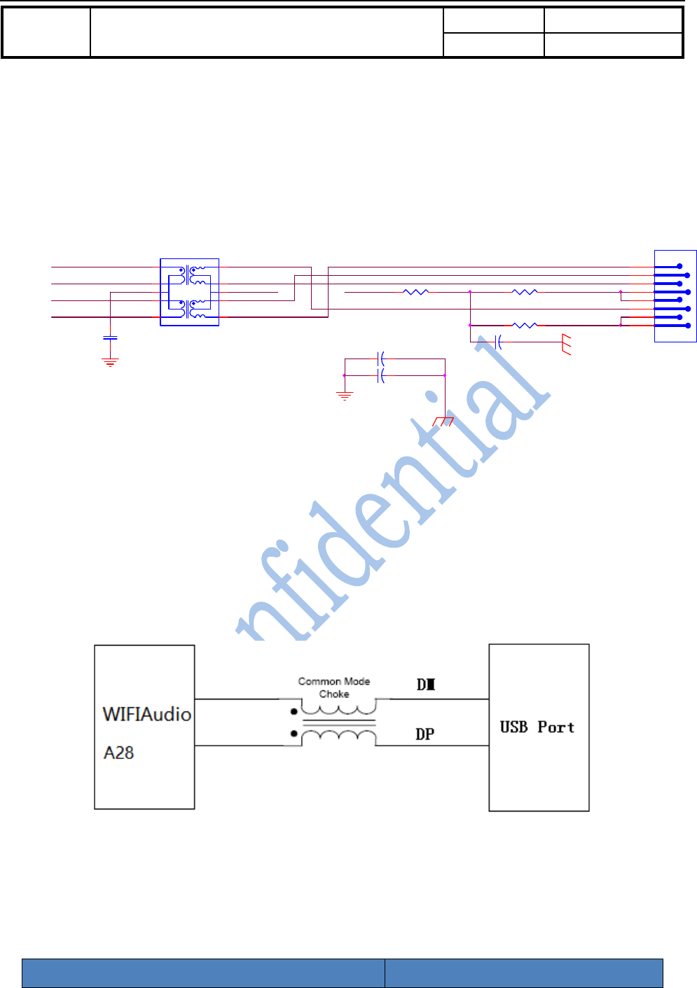
A28 module provides 10/100Mbps Ethernet interface pins that could be used to connect with Ethernet RJ45 socket.
It has built-in transformer.
DocTitle Wirelesssmartaudiomodule Number WMB20150921
Version 1.0
Document No.: WMB20150921 Page 12 of 20
2.5.1. Connect the module with RJ45
To provide 10/100Mbps Ethernet functionality, you could connect the module with the RJ45 socket via a Ethernet
transformer. The detailed diagram is as follows:
R100 75R
12
R95 75R
12
GND
U5
RJ-45X1P
1
2
3
6
4
5
7
8
CHGND
C84 0 ohm/SB
1 2
GND
C85 0 ohm/SB
1 2
WAN_C2
ETH_RXP
ETH_RXN
WAN_C1
ETH_TXP
ETH_TXN
MB4_P MB4_P
LAN PORT1
MA4_P
CAP3 CMT4
CHGND
MA4_N
MB4_N
MA4_N
MA4_P
CMT4
MB4_N
C86
0.1uF
12
RX
TX
D X
U4
HN1674DG
1
3
5
7
16
14
13
12
10
4R94 75R
12
C87 1000pF/2KV/NC
1 2
Figure 2-4 The reference design of Ethernet
2.6. USB host port
A28 module provides high speed USB2.0 host interface. To connect with USB port, the reference design is shown
below.
Figure 2-5 USB host interface
Please follows the following design rule to populate the USB host interface:
Item Parameter

DocTitle Wirelesssmartaudiomodule Number WMB20150921
Version 1.0
Document No.: WMB20150921 Page 13 of 20
Signal Group USB
Topology Differential Pair Point-to-Point
Reference Plane Ground Referenced
Characteristic Trace Impedance (Zo) 90 Ω ±10%
Trace Width 4 mils
Serpentine Spacing(center to center) 8.5 mils
Minimum Isolation Spacing to Clock Signals 50 mils
Minimum Isolation Spacing to Low-Speed Signals 20 mils
Minimum Isolation Spacing to other USB Pair 20 mils
Total Length (with package length) Max = 8000 mils
Maximum Recommended Via Count 2 (per side)
DM to DP Length Matching(with package length) Match total length to within ±10 mils
Table 2-6 WiFiAudio-A28 USB design rule
2.7. Power supply
A28 module can be powered with single power supply with voltage between 3.5V and 5.5V. The peak current is
around 300mA, the normal working current is 170mA. In sleep mode (when Wi-Fi is off), the current is 20mA.
The power supply is important for system stability and Wi-Fi performance. It is recommended to use 100uF and
10uF decoupling capacitor in parallel to reduce the ripple of power supply.
3. Software
WiFiAudio-A28 supports Airplay and DLNA functionality:
Items Description
iOS version iOS 4.2 and above
iPhone,iPad,iPod Touch,iPad Mini
iTune version iTunes 10.2 and above
PC, iMac
Network setup A28 works in AP Client mode
Support WPS and proprietary Wi-Fi setup
Support Airplay mode Play, Pause, Seek, Volume, Prev, Next
Airplay applications Apple Music App.
QQ Music
iTunes

DocTitle Wirelesssmartaudiomodule Number WMB20150921
Version 1.0
Document No.: WMB20150921 Page 14 of 20
Many third party music applications …
DLNA operations Play, Pause, Seek, Volume, Prev, Next
DLNA applications Compatible with DLNA certified player, i.e.,
Skifta
BubbleUPnP
Audio format support MP3, WMA, WAV, Apple Lossless (ALAC), AAC, AAC+,
FLAC, APE, OGG
Browser support PC:IE9/10, Chrome, Firefox
iOS/MAC OS: Safari
Language support of Web server Chinese
English
Setup with web server Setup A28 network
Setup A28 device name, add password protection
Update A28 firmware and restore factory setting
Online update firmware
Connect device to Internet
Table 3-1 A28 software description
3.1. Airplay introduction
AirPlay is the streaming standard developed by Apple Inc. It lets you wirelessly stream what’s on your iOS device
to your HDTV or speaker. It is supported starting from iOS4.2 and OS X Mountain Lion. It can also stream the
music in PC or Mac via iTunes 10.1 or above.
When the user devices (including iMac, PC, iPod touch, iPhone, iPad) are in the same WiFi LAN with the speaker
that supports Airplay, when the user device launches the applications such as iTunes or iOS music applications, the
Airplay button appears. When click the Airplay button, please choose the speaker that you want to stream
to.
3.2. DLNA introduction
Digital Living Networrk Alliance (DLNA) is an organization formed by companies in consumer electronics,
cellphone and PC fields. The device with DLNA certification could seamlessly works with other DLNA devices
without compatibility issue. The device has logo.
DocTitle Wirelesssmartaudiomodule Number WMB20150921
Version 1.0
Document No.: WMB20150921 Page 15 of 20
3.3. WiFi mode
WiFiAudio-A28 module is working at WiFi AP Client mode. To setup AP client mode, please setup with web
browser when you connect with the device via WiFi or Ethernet.
3.3.1. AP Client mode
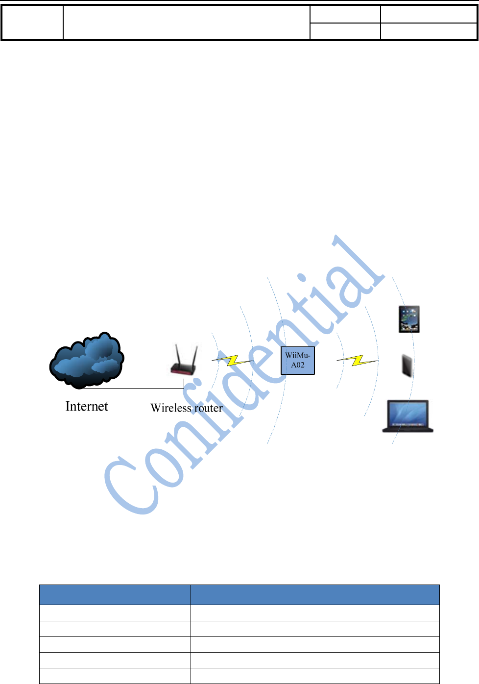
Device working under AP Client could serve as AP and client simultaneously. When it is used as AP, other wireless
device could connect with it directly. Meanwhile, it could connect to other wireless AP as a wireless station. In this
mode, device could connect with WiFiAudio-A28 and playback music to this device with airplay or DLNA.
Meanwhile, if WiFiAudio-A28 is connected with main wireless AP that is connected to Internet, the device that is
connected with WiFiAudio-A28 has access to Internet too.
Figure 3-1 WiFiAudio-A28 AP Client mode
3.4. Web Server setup
WiFiAudio-A28 module provides built-in web server to let user configure the module via the Internet browser.
In the factory mode, the SSID of WiFiAudio-A28’s AP port is in the form of WiFiAudio_xxxx. The xxxx represent
four digital numbers. The IP address, user name and password are shown below:
Parameters Defaultsetting
SSID WiFiAudio _xxxx
IP address 10.10.10.254
Mask 255.255.255.0
DNS WiiMu.com
User name admin

DocTitle Wirelesssmartaudiomodule Number WMB20150921
Version 1.0
Document No.: WMB20150921 Page 16 of 20
Password admin
Table 3-2 WiFiAudio-A28 AP default parameters
You could use PC, iOS or Android device connect the WiFiAudio-A28 first as wireless AP, then launch the browser
and login to web server and configure the module. It supports IE8.0 or up, Chrome and Safari Internet browser.
3.4.1. Web server login
When the user devices are in the same network as WIFIAudio-A28 the user could login to the built-in web server
by entering “http://10.10.10.254” or “http://wiimu.com” in the Internet browser. Currently, both English and
Chinese language are supported in the web server and could be configured in the setup page. However, it is also
possible to add other language support. The following example is shown in English as it is selected as the default
language in the web server.
If the WIFIAudio-A28 device is not connected to another AP to get Internet access, the web server will be directed
to the WIFI setup page. In this page, the user could choose the AP to connect. Otherwise, if it is already connected
with another AP, it will be redirected to the setting page for other settings.
3.4.2. Connecting the module to another AP
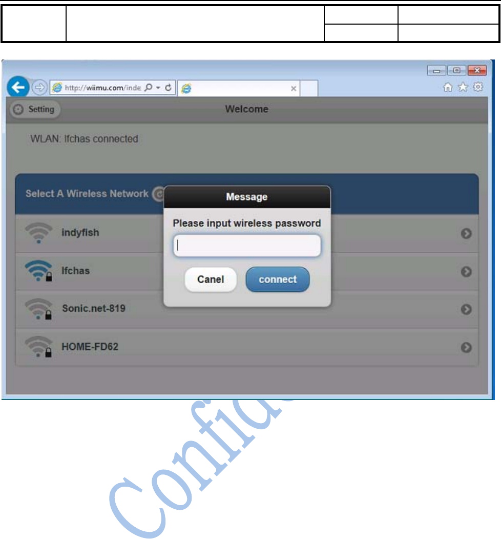
In this page, the network information such as the connected AP and list of available AP are displayed. Please see
the details in Figure 3-2. The user could select the AP to connect to provide the module with Internet access.
Meanwhile, the module could serve as the AP for other devices that could directly connect with the module. In the
case, the module worked as “AP client” or so called bridge mode.
DocTitle Wirelesssmartaudiomodule Number WMB20150921
Version 1.0
Document No.: WMB20150921 Page 17 of 20
Figure 3-2 Connect WiFiAudio-A28 with another AP
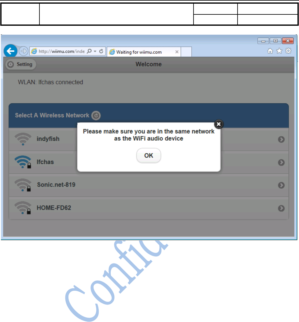
After entering the password for the connected AP, there is pop up message window to remind you that the user
device should be in the same network as WiFiAudio-A28 in order to use it , i.e., the user device is connected to the
module directly or the AP that the module is connected to.
DocTitle Wirelesssmartaudiomodule Number WMB20150921
Version 1.0
Document No.: WMB20150921 Page 18 of 20
Figure 3-3 Keep the device and WIFIAudio-A28 in the same network
3.4.3. Advanced setting for the module
Press the setting button in top left corner of the WiFi setup page to enter the page for advanced settings. There are
three setting fields such as device information, module and wireless LAN setting.
3.4.3.1. Module setting page
It is used to perform manual software upgrade, restore factory settings and setup the default language.
3.4.3.1.1. Software upgrade
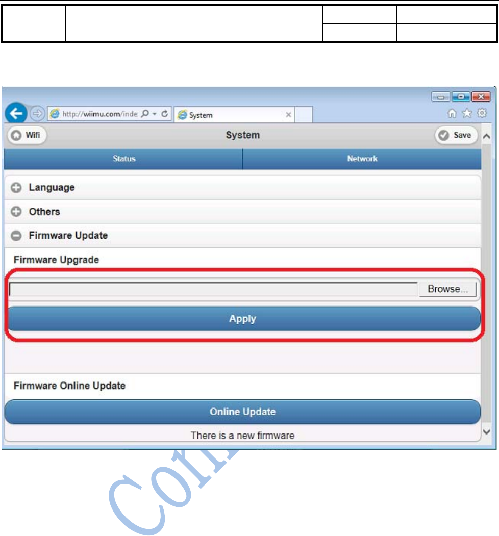
Important: software upgrade is the critical operation so please be cautious of doing this. In the process of
software upgrade, please don’t playback any music or any other operation except the software upgrade.
Please don’t disconnect the power for the module during the process.
It is also possible to use the online update if the device is connected with the Internet by press the “Check Online
update” button in the software upgrade page. The module will then check if there is updated version in the remote
DocTitle Wirelesssmartaudiomodule Number WMB20150921
Version 1.0
Document No.: WMB20150921 Page 19 of 20
maintenance server.
Figure 3-4 Upgrade the module firmware manually
3.5. Use UART to debug
The UART needs setup as follows:
Baud rate 57600
Data bit 8
Parity bit None
Stop bit 1
Flow control
DTR/DSR None
RTS/CTS None
XON/XOFF None

DocTitle Wirelesssmartaudiomodule Number WMB20150921
Version 1.0
Document No.: WMB20150921 Page 20 of 20
3.6. WPS Setting
WPS (Wi-Fi Protected Setup) is used to simplify the Wi-Fi setup. Working with WPS enabled router, user doesn’t
need choose the Wi-Fi SSID and enter password. Instead, user just needs press the button (PBC mode) and it will
join the network safely.
To enter the WPS mode, keep low pulse ( 300ms < t <5s) for “nReload” pin in A28 module.
3.7. Restore to factory setting
To restore the factory setting for the module, keep low pulse for t >5s for “nReload” pin in the A28 module. When
the factory setting is restored, the system will reboot automatically.
FCC Warning
This device complies with Part 15 of the FCC Rules. Operation is subject to the following two conditions:
(1) this device may not cause harmful interference, and
(2) this device must accept any interference received, including interference that may cause undesired operation.
NOTE: Any changes or modifications to this unit not expressly approved by the party responsible for compliance
could void the user's authority to operate the equipment.
FCC Radiation Exposure Statement:
This equipment complies with FCC radiation exposure limits set forth for an uncontrolled environment. End users
must follow the specific operating instructions for satisfying RF exposure compliance.
Note 1: This module certified that complies with RF exposure requirement under portable or mobile or fixed
condition, this module is to be installed only in portable or mobile or fixed applications.
A portable device is defined as a transmitting device designed to be used so that the radiating structure(s) of the
device is/are within 20 centimeters of the body of the user
A mobile device is defined as a transmitting device designed to be used in other than fixed locations and to
generally be used in such a way that a separation distance of at least 20 centimeters is normally maintained
between the transmitter's radiating structure(s) and the body of the user or nearby persons. Transmitting devices
designed to be used by consumers or workers that can be easily re-located, such as wireless devices associated
with a personal computer, are considered to be mobile devices if they meet the 20 centimeter separation
requirement.
A fixed device is defined as a device is physically secured at one location and is not able to be easily moved to
another location.
Note 2: Any modifications made to the module will void the Grant of Certification, this module is limited to OEM
installation only and must not be sold to end-users, end-user has no manual instructions to remove or install the
device, only software or operating procedure shall be placed in the end-user operating manual of final products.
Note 3: The device must not transmit simultaneously with any other antenna or transmitter.
Note 4: To ensure compliance with all non-transmitter functions the host manufacturer is responsible for ensuring
compliance with the module(s) installed and fully operational. For example, if a host was previously authorized as
an unintentional radiator under the Declaration of Conformity procedure without a transmitter certified module
and a module is added, the host manufacturer is responsible for ensuring that the after the module is installed and
operational the host continues to be compliant with the Part 15B unintentional radiator requirements. Since this
may depend on the details of how the module is integrated with the host, LM Technologies Ltd. shall provide
guidance to the host manufacturer for compliance with the Part 15B requirements.
Note 5: FCC ID label on the final system must be labeled with “Contains FCC ID: 2AAPP-A28” or “Contains
transmitter module FCC ID: 2AAPP-A28”.
The transmitter module must be installed and used in strict accordance with the manufacturer's instructions as
described in the user documentation that comes with the host product. Wiimu Information Technology Inc. is
responsible for the compliance of the module in all final hosts.