Williams Sound T45 Portable Hearing Assistance Transmitter User Manual
Williams Sound, LLC Portable Hearing Assistance Transmitter
UserManual.wiki
>
Williams Sound
>
T45 User Manual
User Manual
Navigation menu
Upload a User Manual
Namespaces
Wiki Guide
HTML
PDF
Info
Views
User Manual
Discussion / Help
Navigation
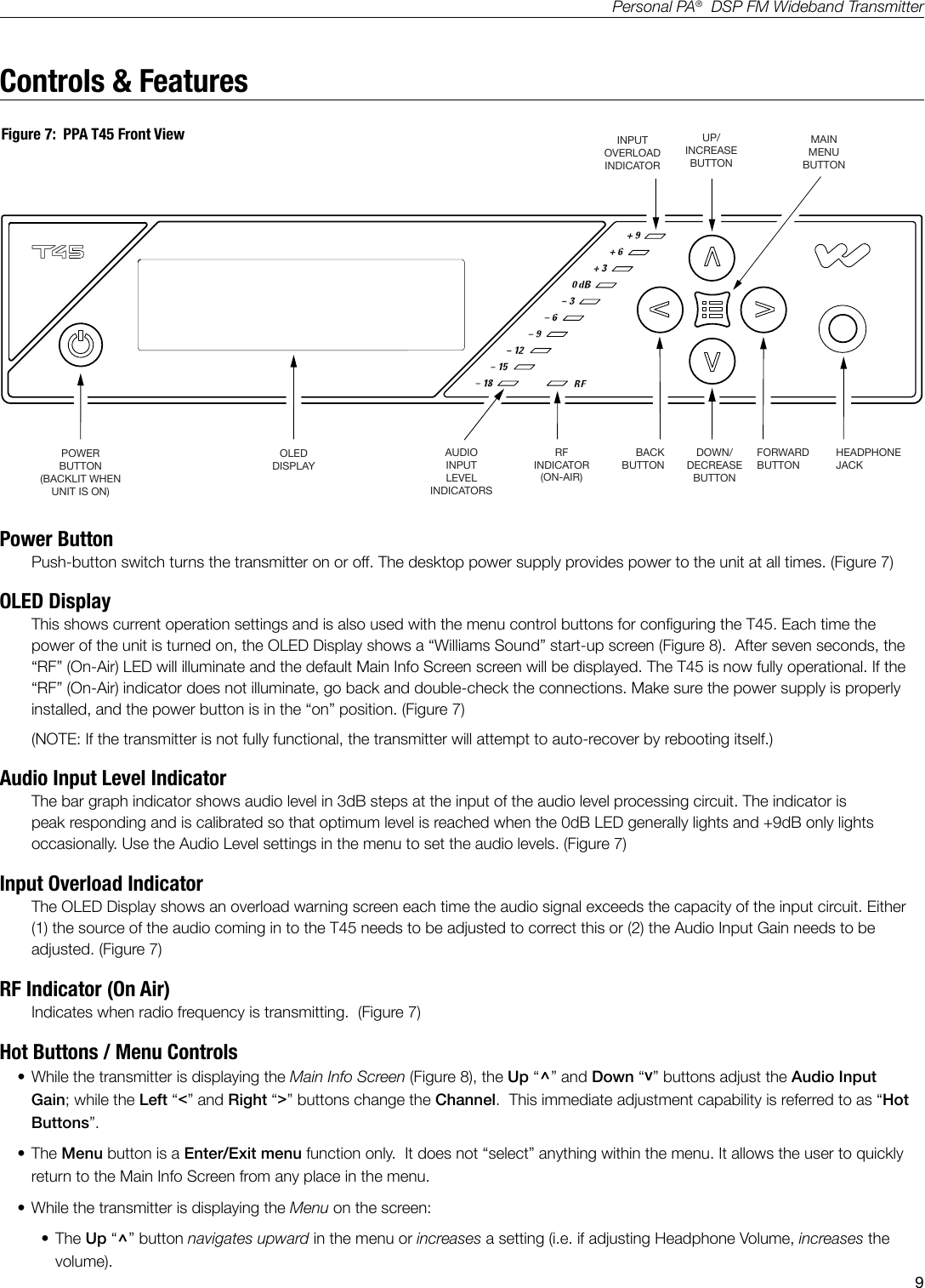
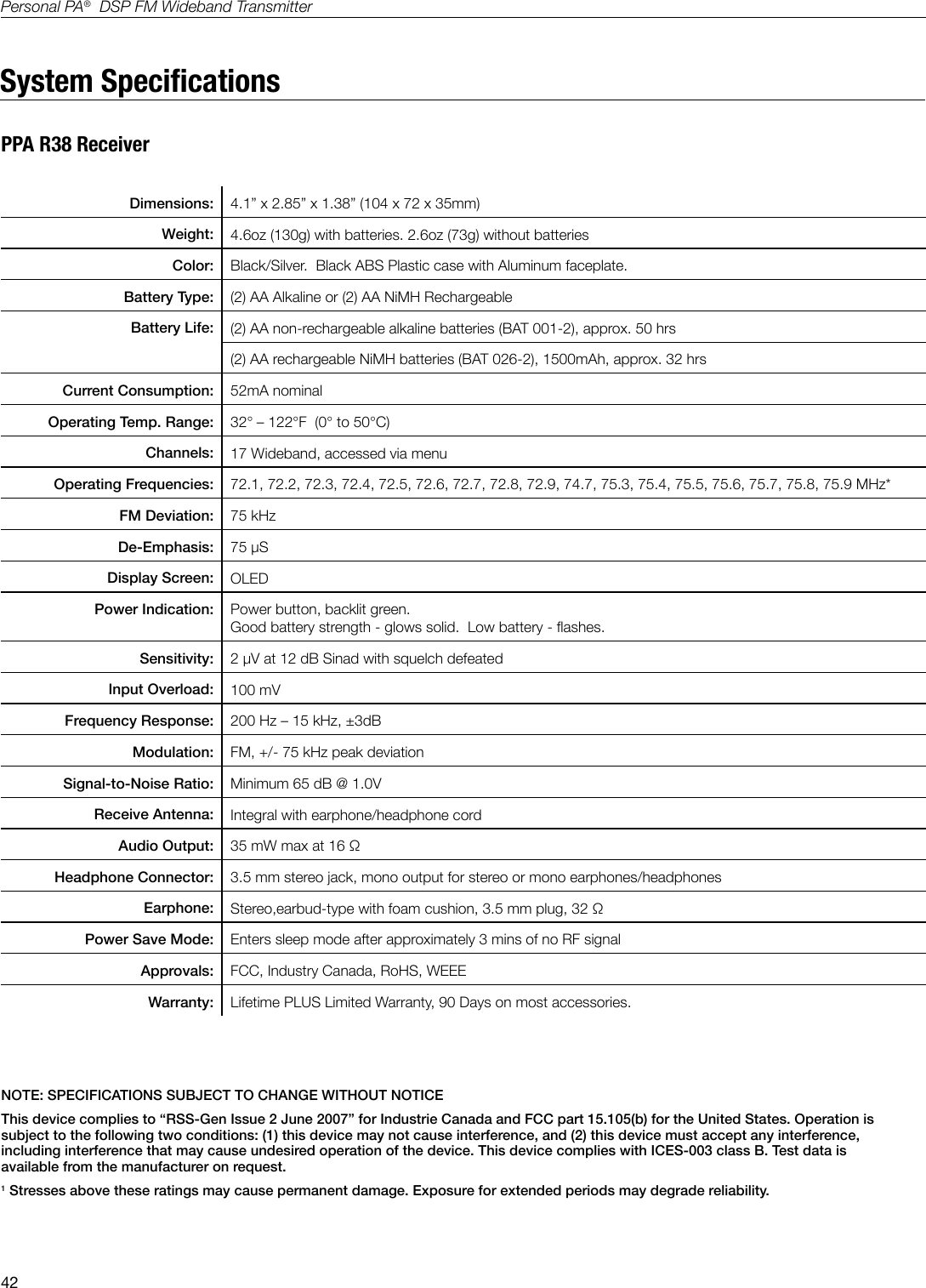
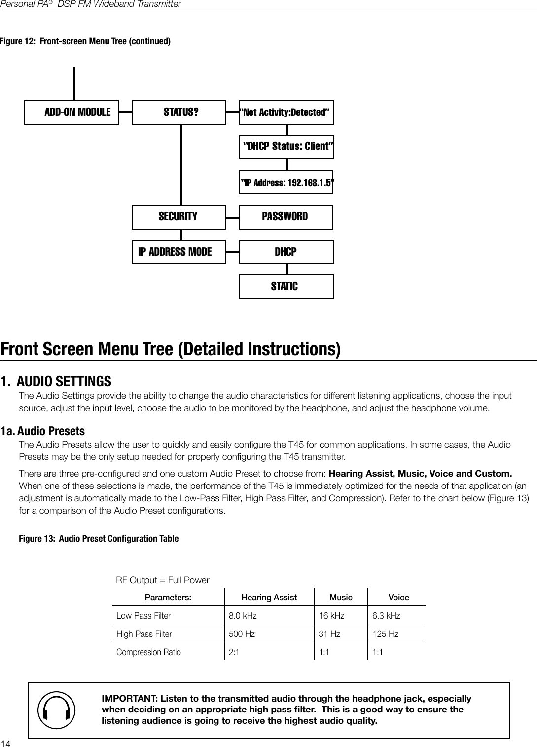
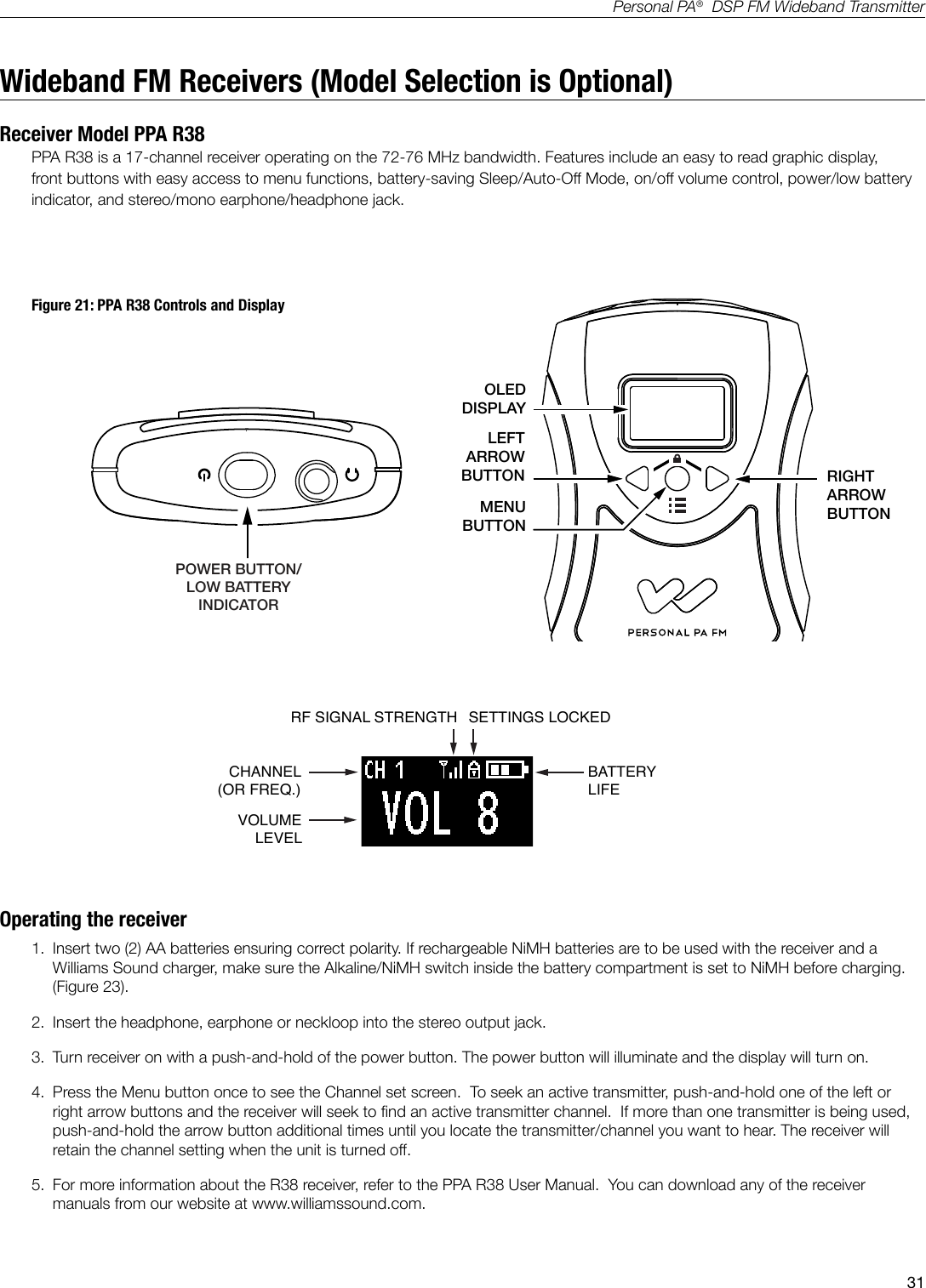
![13Personal PA® DSP FM Wideband TransmitterRF SETTINGS RF CHANNELRF OUTPUT POWERCH 1 - CH 17FULLRF TIME-OUTDISPLAY MODECHANNEL MODESCREEN TIME-OUTPREFERENCESDESCRIPTION SECOND CHARACTER LAST CHARACTER]A406Scroll up/down A to Z Scroll up/down A to ZMEDIUMLOWOFF30 MIN4 HRALWAYS ONFREQUENCYCHANNEL NUMBER17-CHANNEL8-CHANNEL10 MIN30 MINRESTORE DEFAULTS120 MINScroll up/down A to ZYES[FIRST CHARACTERNOADD-ON MODULENew Description SavedALWAYS ONFigure 11: Front-screen Menu Tree (continued)](https://usermanual.wiki/Williams-Sound/T45/User-Guide-2108525-Page-13.png)
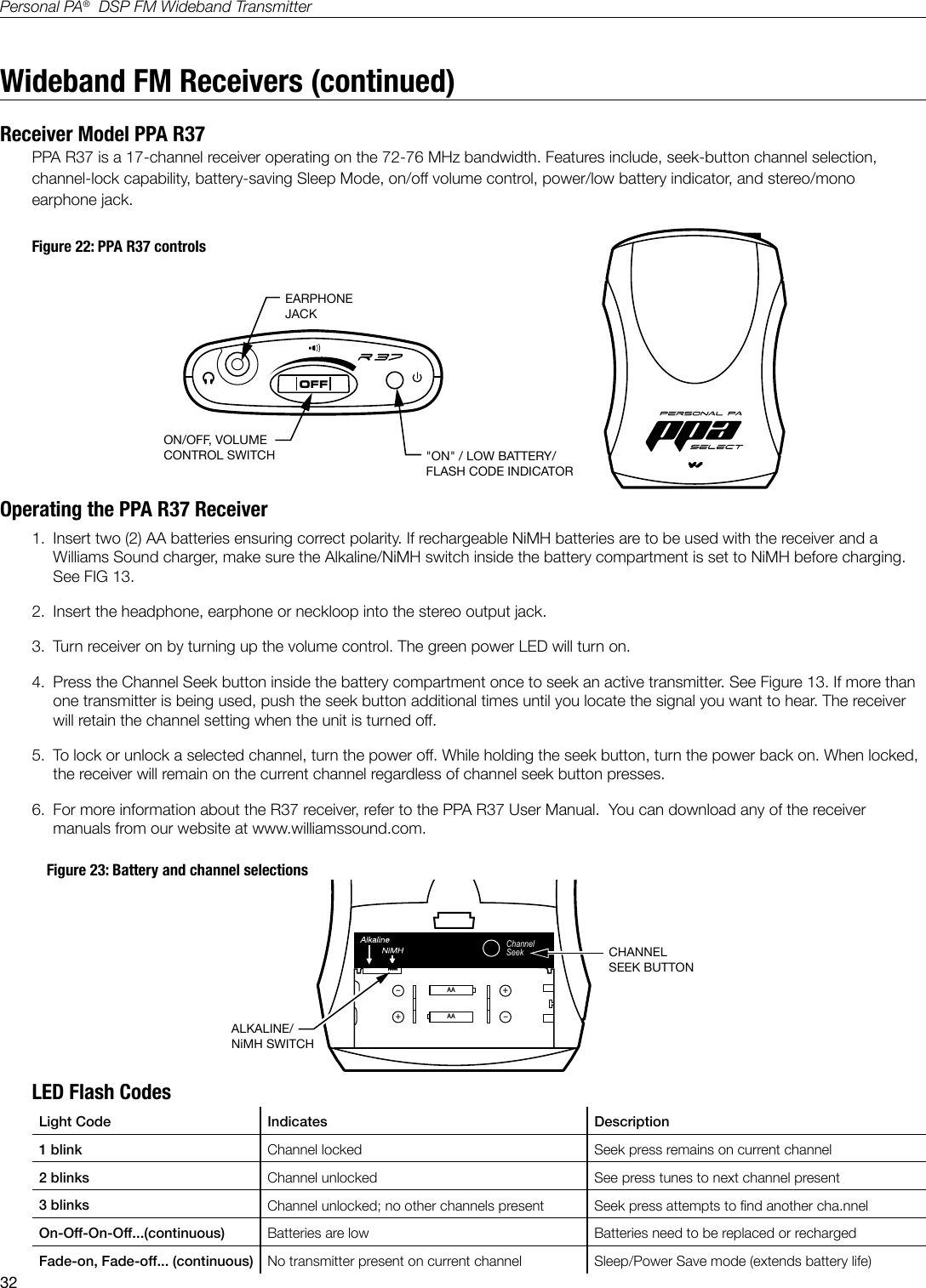
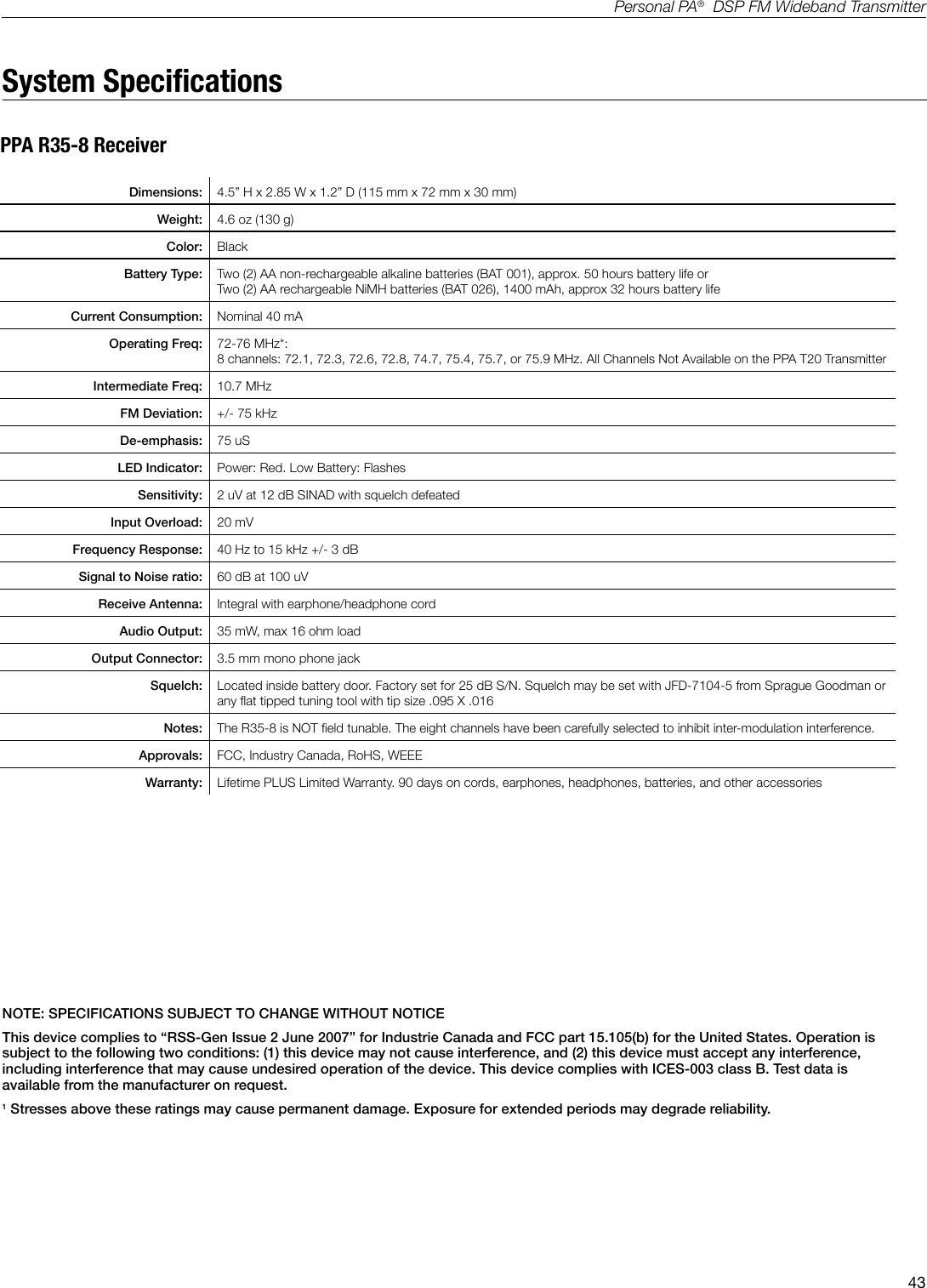
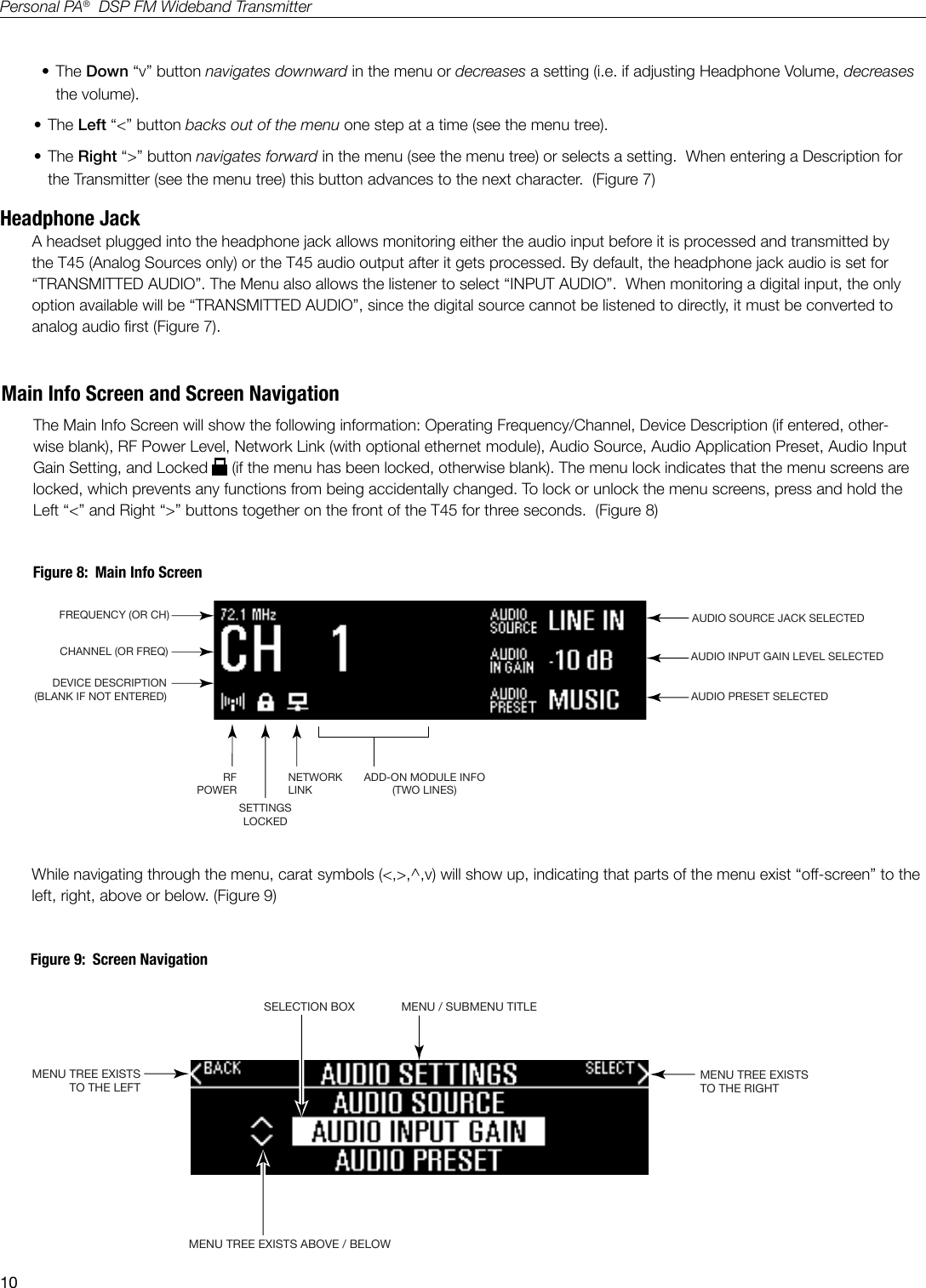
![39Personal PA® DSP FM Wideband TransmitterRemote Control is not working over the hardwired Ethernet network• Please note: If you have a network system administrator, please contact them rst before attempting to troubleshoot the network yourself. The following steps are things you can try on a small, non-managed network. • In this situation you have to check the entire signal path between the control device (laptop or desktop computer) and the T45. You can save some time by “pinging” the router and T45. Pinging allows you to verify the wiring path without physically having to trace the wires themselves.1. In order to perform these steps you will need the IP address of the T45 and the router. You can nd the IP address of the T45 by going into the Menu on the T45 itself (using the front buttons and display). 2. Make sure the T45, Router, and any other devices in the signal path (i.e. an ethernet switch) are all ON.3. You can save time tracing wiring/hardware paths with these next three steps: 4. Open a CMD window on the computer. (For example, to do this on a Windows XP/Vista/or 7-based PC, click on the Windows symbol on the lower left corner of the screen. In the search box, type “CMD”. A black box should come up and the cursor will be blinking.) 5. Type “ping” followed by a space, followed by the IP address of the T45, and hit Enter. If you see a “reply from...[ip address]” this means the hard-wired ethernet path is ok. If this is ok, skip to step 9. If you see “request timed-out”, there is most-likely a break in the wiring path between the computer and the T45. 6. Try “pinging” the IP address of the router. If you can get a reply from the router, but not the T45, the problem is either in the wiring between the router and T45, or the T45 itself could be malfunctioning. If the router doesn’t ping, go to step 7.7. Now you’ll have to check all of the wiring between the computer and the T45. Make sure every device in the signal path is plugged in and turned ON. Re-seat (unplug and plug back in rmly) all ethernet cables in the path between the computer and the T45. If you nd one that was loose, plug it in and go back to step 5. Keep repeating this process until the T45 pings successfully.8. If no loose cables were found in step 7, try re-booting (1) the router (2) the computer and (3) the T45 (turn it off for 10 sec then turn it back on). Wait at least two full minutes for the T45 to re-establish itself on the network. Then try pinging it again (go back to step 5).9. At this step you have veried that you can ping the T45 from the computer. Open an internet browser on the computer. Type the IP address of the T45 into the address bar of the Internet browser. (i.e. it will be something like 192.168.1.100) Or, if the address is already there from a previous connection, just refresh the browser.10. Verify the connection by changing a setting on the T45 through the internet browser. If you can change settings and get feedback on the web page (or verify the change on the front display of the T45) you are now connected to the T45.11. If you can make changes to the T45 initially but then lose that ability (get disconnected), you may have to look at deeper network issues such as IP address conicts, power issues, or even settings in the router. 12. You can try restoring the T45 to factory settings. This will clear out any changes and allow you to start clean with a known IP address (you will need to enter it). Make sure when entering a static IP address that it is compatible with the network IP structure, and also does not conict with any other device IP addresses on the network. After this is done, go to step 9. If step 10 doesn’t work, go back to step 5.13. If you have tried all of these steps and still can’t connect, call Williams Sound for additional troubleshooting help. Note that Wlliams Sound cannot help in all cases, as there are many variables within networks.](https://usermanual.wiki/Williams-Sound/T45/User-Guide-2108525-Page-39.png)
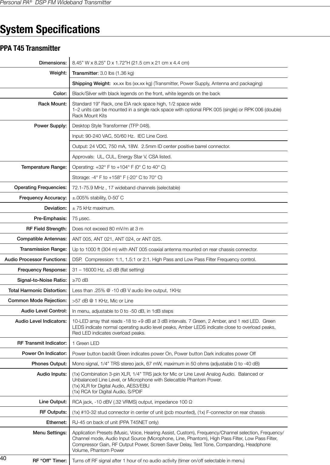
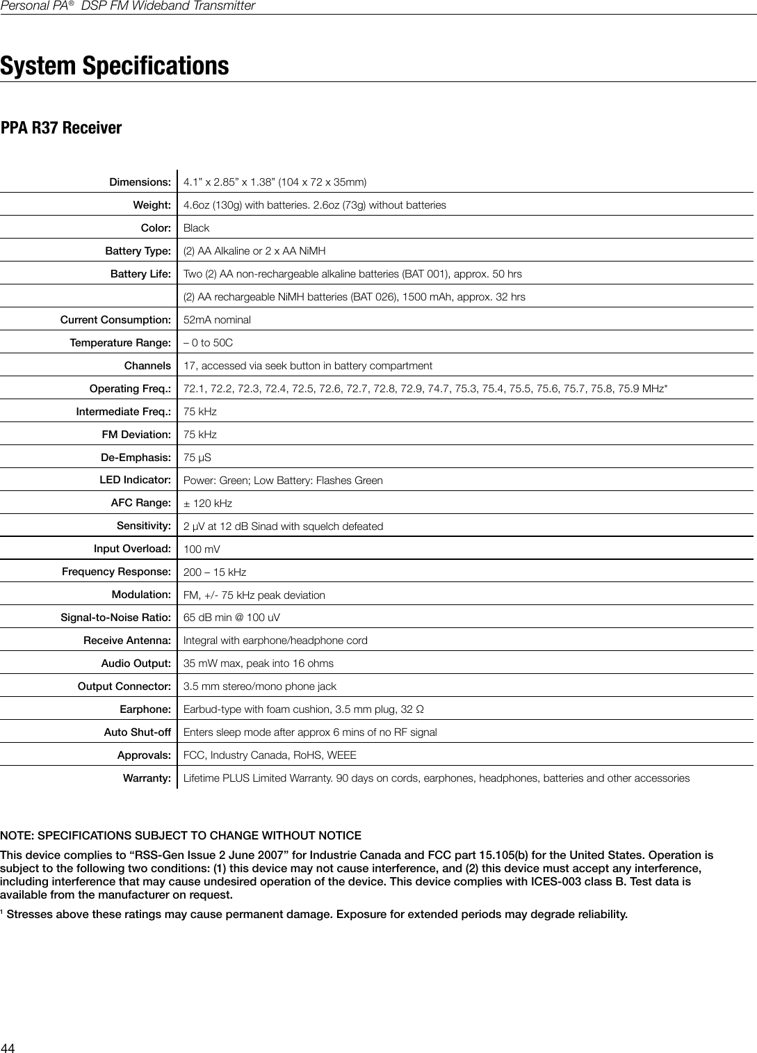
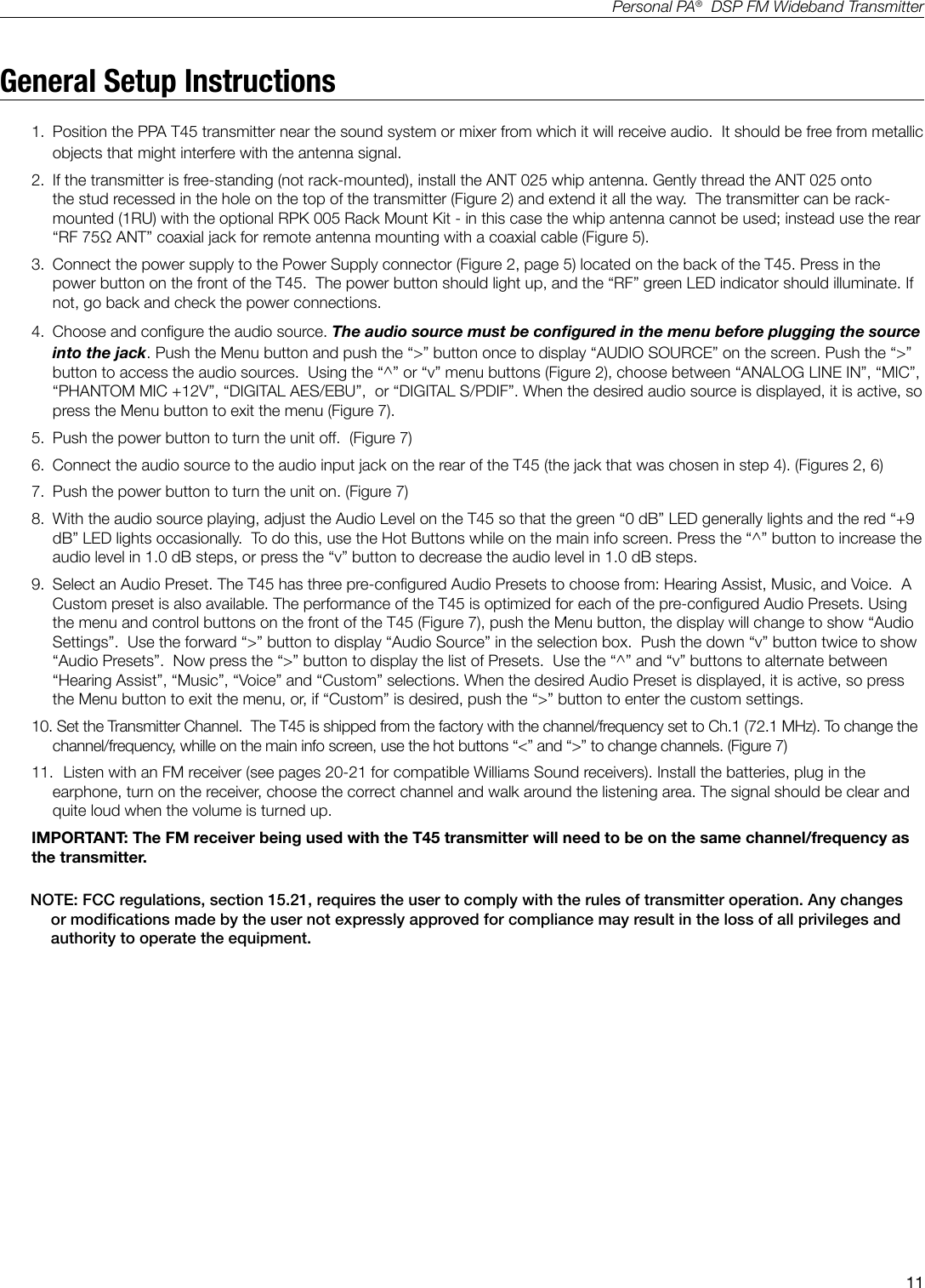
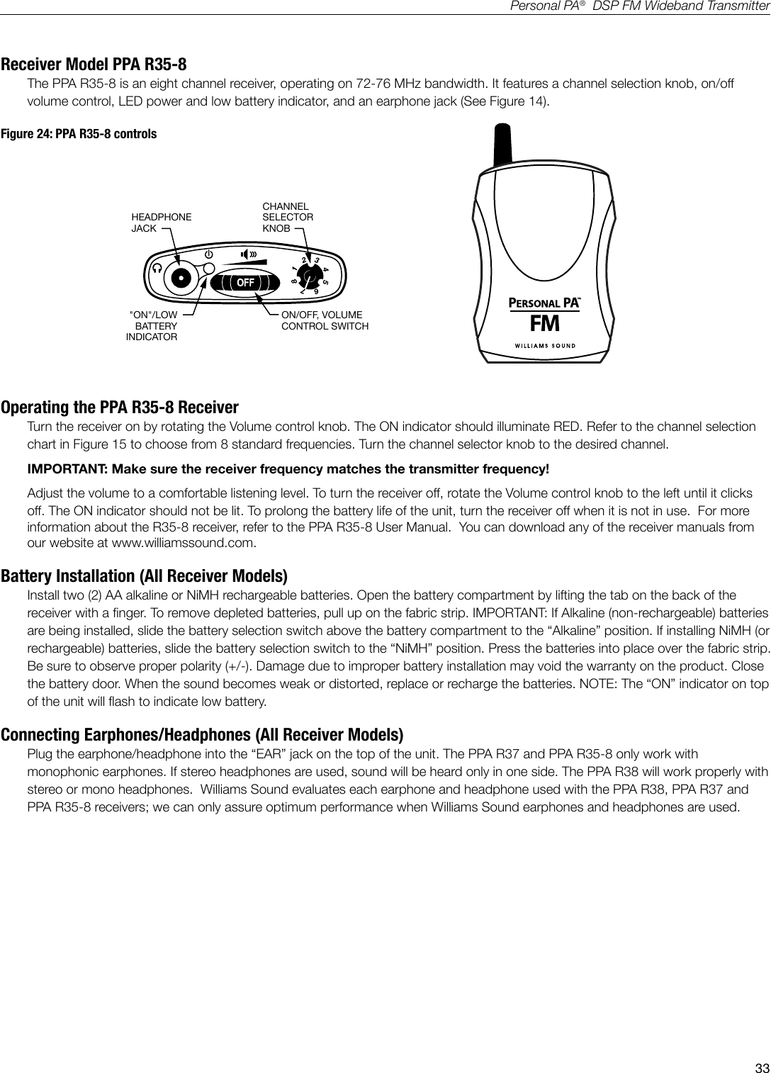
![41Personal PA® DSP FM Wideband TransmitterSystem SpecicationsPPA T45 Transmitter (continued)Input Levels (Bal or Unbal): Nominal (1st Amber LED) Maximum (Input Overload LED) Absolute Maximum Ratings** Microphone: -60dBV (1 mV RMS) -20 dBV (100 mV RMS) +20dBV (10.0 V RMS) Line: -8dBV (400 mV RMS) +16 dBV (6.3 V RMS) +20 dB V (10.0 V RMS)Max. Phantom Power: 12 volts (DIN 45596) on the 3-pin XLR connectorApprovals: FCC, RoHS2, WEEE, Industry CanadaWarranty: Lifetime PLUS Limited Warranty (90 Days on most accessories)NOTE: SPECIFICATIONS SUBJECT TO CHANGE WITHOUT NOTICE** Stresses above these ratings may cause permanent damage. Exposure for extended periods may degrade reliability.This device complies with “RSS-Gen Issue 2 June 2007” for Industry Canada and FCC part 15.105[b] for the United States.Operation is subject to the following two conditions: [1] this device may not cause interference, and [2] this device must accept any interference, including interference that may cause undesired operation of the device.This device complies with Industry Canada licence-exempt RSS standard(s). Operation is subject to the following two conditions: (1) This device may not cause interference, and (2) this device must accept any interference, including any interference that may cause undesired operation of the device. Cet appareil est conforme à la norme RSS Industrie Canada exempt de licence. Son fonctionnement est soumis aux deux conditions suivantes: (1) cet appareil ne doit pas provoquer d’interférences et (2) cet appareil doit accepter toute interférence, y compris les inter-férences pouvant causer un mauvais fonctionnement du dispositif.This device complies with ICES-003 class B. Test data is available from the manufacturer on request.Note: This equipment has been tested and found to comply with the limits for a Class B digital device, pursuant to part 15 of the FCC Rules. These limits are designed to provide reasonable protection against harmful interference in a residential installation. This equip-ment generates, uses uses and can radiate radio frequency energy and, if not used in accordance with the instructions, may cause harmful interference to radio communications. However, there is no guarantee that interference will not occur in a particular installation. If this equipment does cause harmful interference to radio or television reception, which can be determined by turning the equipment off and on, the user is encouraged to try to correct the interference by one or more of the following measures:-Reorient or relocate the receiving antenna.-Increase the separation between the equipment and the receiver.-Connect the equipment into an outlet on a circuit different from that to which the receiver is connected.-Consult the dealer or an experienced radio/TV technician for help.Note: FCC regulations, section 15.21, requires the user to comply with the rules of transmitter operation. Any changes or modifications made by the user not expressly approved for compliance may result in the loss of all priveleges and authority to operate the equipment.](https://usermanual.wiki/Williams-Sound/T45/User-Guide-2108525-Page-41.png)