Wilson Electronics 2B5125 TRI-BAND SIGNAL BOOSTER User Manual
Wilson Electronics, LLC TRI-BAND SIGNAL BOOSTER
User Manual
Contents:
Accessories ..................................................................... 1
How it Works .................................................................... 2
Vehicle Installation Diagram ........................................................ 2
Install the Outside Antenna ......................................................... 2
Power up the Wilson Electronics Sleek ............................................... 3
Adjusting the Sleek Arms .......................................................... 4
Understanding the Sleek Lights ..................................................... 4
Troubleshooting .................................................................. 4
In-Building Installation ............................................................. 5
Warnings ........................................................................ 6
About Wilson Electronics ........................................................... 6
Signal Booster Specications ...............................................Back Cover
To boost your phone’s signal power, the phone must be placed in the Sleek cradle. For best results, use a
Bluetooth® headset or hands free device, while the phone remains in the Sleek.
Cellular Signal Booster with Built-in Antenna
operates on 700 MHz Band 13 / 800 MHz / 1900 MHz
(Band 13 is Verizon Wireless™ LTE)
Appearance of device and accessories may vary.
Note: This manual contains important safety and operating information. Please read and follow the
instructions in this manual. Failure to do so could be hazardous and result in damage to your Sleek.
®
(Band 13 is *
1Contact Wilson Electronics Technical Support Team with any questions at 866-294-1660
or email: tech@wilsonelectronics.com. Mon.- Fri. Hours: 7 am to 6 pm MST.
2
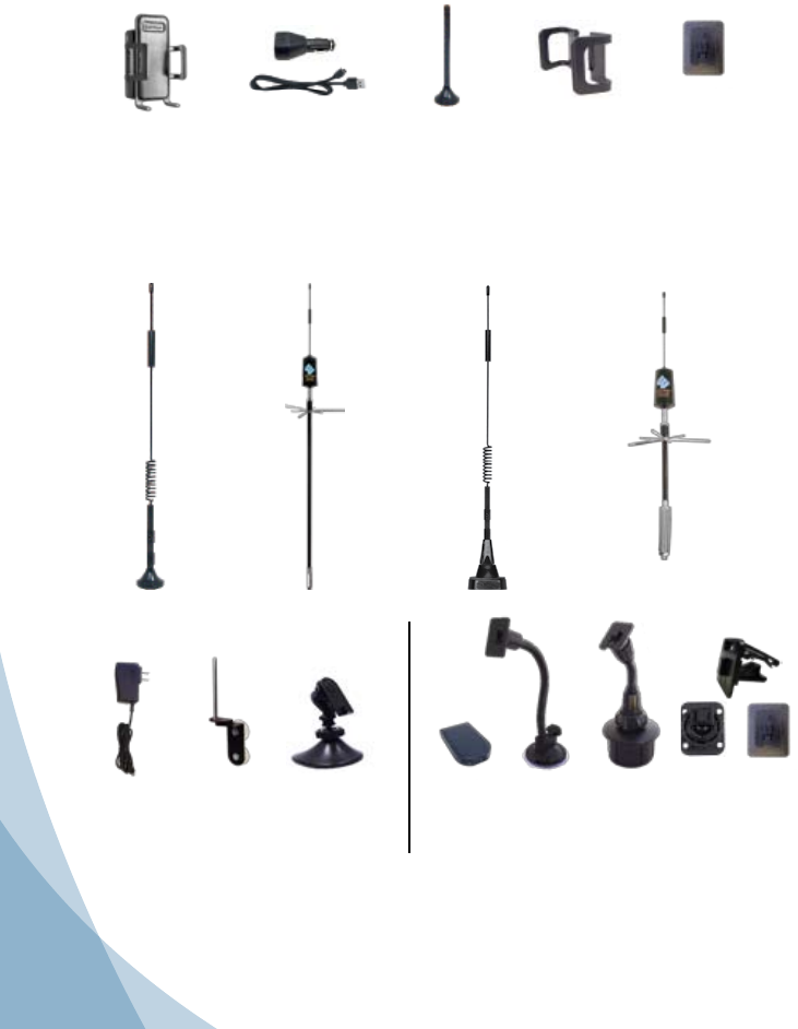
Antenna Options
Although the convenient Mini-Magnet Mount Antenna may have been included with your kit, Wilson
Electronics offers a wide variety of Outside Antennas to help you customize your Signal Booster for a
specic application. All models shown below double the power to the cell tower compared to the Mini-
Magnet antenna. See your dealer or visit www.WilsonElectronics.com for more information.
AC Power Supply
*(859969)
Gooseneck
Suction Cup
Cradle Mount
(901120)
Cup Holder
Cradle Mount
(901130)
Adjustable
Desk Mount
*(901137)
Accessories for your Sleek®
NMO Mount
Antenna
(301104)
For permanent
vehicle roof mount
on cars and
pickup trucks.
Ideal for mounting
on non-metal
surfaces.
Mounts on
Wilson NMO style
mounts: 901101,
901102, and
901103
* Must utilize
971119 Adapter
(SMA-FME)
Trucker
Antenna
(301101)
Designed for
mirror mounting
on large trucks.
Mounts on Wilson
3/8” mounts:
901104 and
901106
* Must utilize
971119 Adapter
(SMA-FME)
12” Magnet
Mount Antenna
(301125)
RV Antenna
(301133)
* Must utilize
971119 Adapter
(SMA-FME)
Antenna Window Mount
(Used with Mini-Magnet
Mount Antenna)
*(901128)
Mini-Magnet Mount
Antenna
(included in some kits)
Vehicle Dash
Adhesive
Mounting Bracket
DC Plug-In
Power Supply
& USB cable
Sleek® Cellular
Signal Booster
FCC requires to never use the cell phone in the cradle next to your ear.
The term “IC” before the radio certification number only signifies that Industry Canada technical specifications were met.
Vehicle Dash
Mounting Kit
-Rugged/Screw Mount-
-Adhesive Mount-
-Vent Clip Mount-
(901134)
(included in some kits)
* All 3 available together in the Home Accessory Kit - 859970
Adjustable Arms
Carrying case included
Appearance of device and accessories may vary.
*(This product is not marketed by Verizon Wireless or AT&T)
Mobile Power
Supply
(859984)
Inside this Package
Sleek® 4G-V operates on 700 MHz Band 13 / 800 MHz / 1900 MHz (Band 13 is Verizon Wireless™ LTE)*
Model #2B5125 FCC: PWO2B5125 IC: 4726A-2B5125
1
2
Contact Wilson Electronics Technical Support Team with any questions at 866-294-1660
or email: tech@wilsonelectronics.com. Mon.- Fri. Hours: 7 am to 6 pm MST.
NOTE: The cell phone must be placed in the cradle to work properly.
Warning: DO NOT use phone covers that have chrome or any other metallic surface. It may block
cellular signals
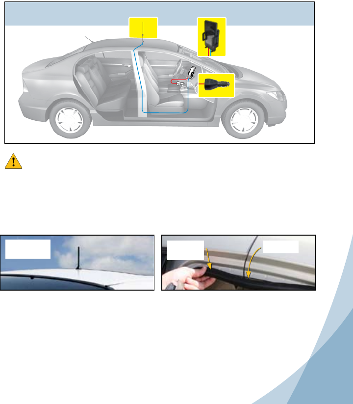
The Outside Antenna must be installed vertically.
Antenna performance will be degraded if the
antenna is not vertical.
The antenna cable is small yet strong enough that it
may be shut in most vehicle doors without damaging
the cable.
For a more professional looking installation, run the
antenna cable under the door seal. Carefully pull
down the door seal. Run the cable under the seal
and push the seal back into place. This prevents
constant wear and tear on the cable as the door
opens and closes. The antenna cable is small
enough to easily tuck under the door seal or
plastic molding.
Mini-Magnet
Mount Antenna
Shown
Carefully
Pull Down
Door Seal
Run Cable
Under Seal
Vehicle Installation
1. Install the Outside Antenna
To receive the best cell signal, select a location for the Outside Antenna that is preferably in the center
of the vehicle’s roof, 12 inches away from any other antennas, free of obstructions, and at least 6 inches
from the rear or side windows or sunroof.
General
Your Wilson Electronics Sleek has been carefully engineered to signicantly improve the performance
of your phone. Together with an Outside Antenna, the Sleek’s state-of-the-art circuitry is designed to
increase your phone’s signal to and from the cell tower. The Sleek reduces disconnects and dropouts
and increases data communication rates on 2G, 3G networks and 4G networks (in some models).
How it Works
With the phone in the cradle and while using a wireless Bluetooth headset (or hands free device) the
Outside Antenna collects the cell tower signal and sends it through the cable to the Sleek. The signal
is then boosted by the Sleek and sent to the phone. When the phone transmits, the signal is picked up
wirelessly and boosted by the Sleek and transmitted back to the cell tower through the Outside Antenna.
Vehicle Installation Diagram
Sleek boosts
signal to and
from cell tower
Outside Antenna
communicates with cell
tower
Sleek w/phone
Sleek w/phone
3Contact Wilson Electronics Technical Support Team with any questions at 866-294-1660
or email: tech@wilsonelectronics.com. Mon.- Fri. Hours: 7 am to 6 pm MST.
4
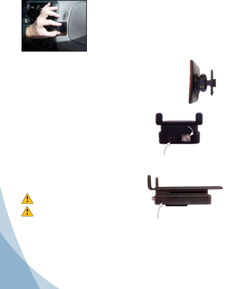
2. Attach the Mounting Bracket
A mounting bracket is provided for attaching the Sleek to your vehicle’s dash. Other options are also
available from Wilson Electronics.
3. Attach the Sleek® to the Bracket
Once you have installed the bracket in the desired location, and waited 24 hours for adhe-
sive to cure, attach the Sleek by aligning the rectangular hole on its back with the tab on
the mount bracket, grasping the sides of the Sleek, and sliding it downward approximately
¼ inch into place.
Once the cradle is attached, you can adjust the angle of the adhesive bracket by applying
gentle pressure to the top or bottom of the Sleek. The bracket is designed to swivel when
the knurled nut is loosened for greater adjustability of the Sleek viewing angle. To lock
bracket into position, tighten large nut.
ADHESIVE BRACKET- Included in this package
1. Clean the area where the bracket is to be mounted with the
supplied alcohol wipe. Allow to dry.
2. Peel the backing to expose the adhesive and press the
bracket onto the desired location in the vehicle. Note: Be sure
the tab is positioned vertically, not horizontally.
3. Allow the adhesive to cure for 24 hours before you attach
the Sleek.
Power up the Wilson Electronics Sleek®
Accessory port to power your phone, some adapters available
through Wilson Electronics at 866-294-1660. (See Figure 2)
Connect the mini-USB plug on the power cable to the Sleek’s mini
USB port located on the bottom of the Sleek and insert the adapter
into the vehicle power adapter of your vehicle. The Sleek may remain
on all the time. However, leaving the Sleek on in a vehicle when it is
not running can discharge the battery in a day or two.
Note: The 12V DC power source on many vehicles is shut off
with the ignition key.
Warning: Use only the supplied Wilson Electronics power
supply.
Warning: Make sure the Outside Antenna cable is
connected before powering up the Sleek.
4. Attach the Outside Antenna cable to the Sleek®
Attach the cable from the Outside Antenna to the antenna connector
on the Sleek. (See Figure 1)
Accessory USB Power port
Figure 2
Sleek Power port. Connect the
Wilson Electronics’s power supply
Antenna
connection
Figure 1
3
4
Contact Wilson Electronics Technical Support Team with any questions at 866-294-1660
or email: tech@wilsonelectronics.com. Mon.- Fri. Hours: 7 am to 6 pm MST.
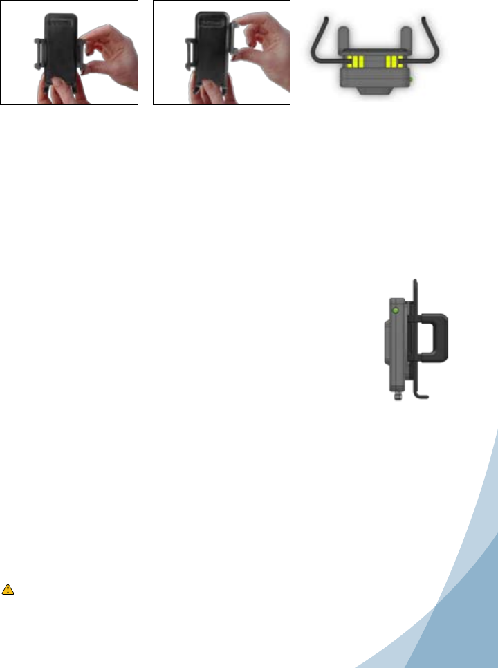
Adjusting the Sleek® Arms
Included with your Sleek are various sized arms, which will provide you with multiple
options to customize the Sleek to t your phone.
1. Change arms
Gently grab the arm and lift
upward until the arm slides
free from the Sleek.
2. Reposition arms
Position the arm above a different slot on the Sleek (indicated by
the yellow in the drawing). Gently slide the arm down until the arm
is rmly in place.
NOTE: The cell phone must be placed in the Sleek to work properly. Use a Bluetooth or wired hands free device.
Green light is on : Sleek is operating properly
SYMPTOM: No light, or light always off
Make sure that the 1. power supply for the Sleek is functioning properly, by making
sure the light located on the power supply is lit.
If the DC plug-in power supply is properly inserted, but the plug’s light doesn’t 2.
come on, then check the 12 volt power from the car socket, and check the fuse
in the DC plug-in power supply.
Troubleshooting
SYMPTOM: No increase in bars
Make sure that the antenna connector is tight.1.
The cell phone must be placed in the Sleek cradle to amplify properly.2.
Call Wilson Electronics Technical Support at 866-294-1660.3.
Understanding the Sleek® Lights
Separation of the Sleek and the Outside Antenna is very important. In a vehicle, the metal roof acts
as a barrier and helps shield the two antennas from each other, preventing oscillation (feedback).
Oscillation can occur when the roof mounted antenna is too close to the Sleek inside the vehicle. An
oscillation (or feedback) in the Sleek is similar to when a microphone is too close to a speaker in a
sound system, resulting in a loud whistle. An oscillation in the Sleek, if allowed to occur, can affect
nearby cell towers’ ability to handle calls.
Warning:
DO NOT use phone covers that have chrome or any other metallic surface. It may block cellular signals
SYMPTOM: Red light is on
If the light is red, the Sleek has powered down to protect the cell tower. See section above “Separation 1.
of Sleek and the outside antenna is very important.” If the light turns red, the Sleek has powered
down to protect the cell tower from oscillation. The red light indicates the outside roof mounted
antenna needs to be moved farther from the Sleek. In a vehicle installation, move the Outside
Antenna on the roof of the car farther to the rear of the car, but at least 6 inches from the rear
or side windows or sunroof. To reset the Sleek, disconnect and reconnect the power supply. If
the light is now green, the Sleek is working properly. If the red light is still on, move the Outside
Antenna farther away and repeat the process.
5Contact Wilson Electronics Technical Support Team with any questions at 866-294-1660
or email: tech@wilsonelectronics.com. Mon.- Fri. Hours: 7 am to 6 pm MST.
6
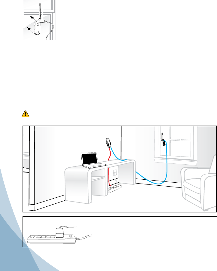
In-Building Installation
Installing a Wilson Electronics Outside Antenna in a Building
Follow the specic antenna instructions included with the Outside Antenna (sold separately except for
certain kits). These instructions assume that you are using a Wilson Electronics Mini-Magnet Mount
Antenna and the optional suction cup window bracket.
To receive the best signal, select a window on the side of your building where your outside signal is the
strongest.
Attach the suction cup bracket to the inside of a window so that the cable will reach
the location of the Sleek. Place the bracket as high on the window as possible for
best performance.
Once the bracket is in place, attach the magnet base of the antenna to the at
surface of the bracket. Note: The antenna must be installed vertically. Signal
performance will be degraded if the antenna is not vertical.
Installing the Wilson Electronics Sleek® Signal Booster in a Building
The Wilson Electronics Sleek may be placed in any convenient indoor location, such as a desk or
tabletop. The cell phone or data card must be in the cradle and a Bluetooth headset used for voice
communications.
Attaching the Antenna
Once you have selected the location for the Sleek, run the cable from the outside antenna and attach it
to the SMA connector on the bottom of the Sleek.
Note: The cell phone must be placed in the Sleek cradle to amplify properly.
Warning: The Sleek and the Outside Antenna must have a minimum separation of 3 feet to
prevent oscillation.
Outside Antenna
communicates
with cell tower
Sleek amplies signal
to & from cell tower
Sleek powered through surge
protected AC Power Strip
IMPORTANT NOTICE
It is very important to power your Signal Booster using a •
surge protected AC Power Strip with at least a 1000 Joule
rating.
Failure to do this will void your warranty in the • event of a
power surge or lightning strike.
Adapter Note: For optimal performance and to maintain a secure connection, we recommend
attaching the included velcro tab. If adapter becomes lose in the port, gently
squeezing the adapter end will restore a snug fit.

5
6
Contact Wilson Electronics Technical Support Team with any questions at 866-294-1660
or email: tech@wilsonelectronics.com. Mon.- Fri. Hours: 7 am to 6 pm MST.
About Wilson Electronics
Wilson Electronics, Inc. has been a leader in the wireless communications industry for over 40 years. The company
designs and manufactures Signal Boosters, antennas and related components that significantly improve cellular phone
signal reception and transmission in a wide variety of applications, both mobile (marine, RV, vehicles) and in-building
(home, office, M2M).
With extensive experience in antenna and Signal Booster research and design, the company’s engineering team uses a
state-of-the-art testing laboratory, including an anechoic chamber and network analyzers, to fine-tune antenna designs
and performance. For its Signal Boosters, Wilson Electronics uses a double electrically insulated RF enclosure and cell
tower simulators for compliance testing.
Wilson Electronics Signal Boosters feature patented Smart Technology ™ that enables them to automatically adjust
their power based on cell tower requirements. By detecting and preventing oscillation (feedback), signal overload and
interference with other users, these Smart Technology ™ Signal Boosters improve network cell phone areas without
compromising carrier systems.
All products are engineered and assembled in the company’s 55,000-square-foot headquarters in St. George, Utah.
Wilson Electronics has product dealers in all 50 states as well as in countries around the world.
Warning: Do not plug in the power supply until the Outside Antenna cable is attached to the Sleek.
Warning: RF Safety: The Sleek cradle/Signal Booster must be installed with a separation of at
least 8 inches from all persons and must not be located in conjunction with any other
antenna or Signal Booster.
Warning RF Safety: The FCC requires that a cell phone with cradle attached may only be used
with the cradle mounted as illustrated in this installation guide. A cell phone held near
the ear must be without the cradle attached.
Warning: RF Safety: All Inside Antennas used with this Signal Booster may not have gain (less
cable Loss) that exceeds 15 dBi and must be located at least 8 inches from all people.
Outside mobile antennas may not have gain (less cable loss) that exceeds 4.6 dBi and
must be located at least 8 inches from all people. Outside xed antennas may not have
gain that exceeds 15 dBi (less cable loss) and must be located at least 25 inches from
all people. All antennas shown on page 1 meet these requirements.
Warning: DO NOT use phone covers that have chrome or any other metallic surface. It may block
cellular signals.
Warnings
30-Day Money-Back Guarantee
All Wilson Electronics products are protected by Wilson Electronics 30-day money-back guarantee. If, for any reason, the performance of any product is not acceptable, simply
return the product directly to the reseller with a dated proof of purchase.
1-Year Warranty
Wilson Electronics Signal Boosters are warranted for one (1) year against defects in workmanship and/or materials. Warranty issues may be resolved by returning the
product directly to the reseller with a dated proof of purchase.
Signal Boosters may also be returned directly to the manufacturer at the consumer’s expense, with a dated proof of purchase and a Returned Material Authorization (RMA)
number supplied by Wilson Electronics. Wilson Electronics shall, at its option, either repair or replace the product. Wilson Electronics will pay for delivery of the repaired or
replaced product back to the original consumer within the continental United States.
This warranty does not apply to any Signal Boosters determined by Wilson Electronics to have been subjected to misuse, abuse, neglect, or mishandling that alters
or damages physical or electronic properties.
Failure to use a surge protected AC Power Strip with at least a 1000 Joule rating will void your warranty.
RMA numbers may be obtained by contacting Technical Support at 866-294-1660.
Disclaimer: The information provided by Wilson Electronics, Inc. is believed to be complete and accurate. However, no responsibility is assumed by Wilson
Electronics, Inc. for any business or personal losses arising from its use, or for any infringements of patents or other rights of third parties that may result from its use.
Copyright © 2012 Wilson Electronics, Inc. All rights reserved.
This device complies with part 15 of the FCC Rules. Operation is subject to the following two conditions:
(1) This device may not cause harmful interference, and (2) this device must accept any interference
received, including interference that may cause undesired operation. Changes or modications made
that are not expressly approved by Wilson Electronics could void authority to operate this equipment.

110807_Sleek English_REV.09_12.20.11
Signal Booster Specications
Sleek 4G-V
Model Number 2B5125
Connectors SMA
Impedance (input/output) 50 ohms
Frequency 746-787 MHz / 824-894 MHz / 1850-1990 MHz
1Passband Gain (nominal)
19 dB (typical) / 23 dB (maximum)
220 dB Bandwidth (nominal) Uplink
Typical / Maximum
Downlink
Typical / Maximum
700 MHz N/A N/A
800 MHz 25 MHz / 28 MHz 28 MHz / 31 MHz
1900 MHz 61 MHz / 67 MHZ 61 MHz / 67 MHz
Power output for single cell phone
(uplink) dBm 700 MHz 800 MHz 1900 MHz
CDMA N/A 29.3 27.8
GSM N/A 28.1 28.3
EDGE N/A 27.5 27.0
WCDMA N/A 26.9 27.5
LTE 26.5 28.4 27.5
Power output for single cell phone (dowlink)
dBm 700 MHz 800 MHz 1900 MHz
CDMA N/A -0.1 -1.3
GSM N/A -0.5 -1.3
EDGE N/A -2.0 -1.6
WCDMA N/A -2.0 -4.2
LTE -2.0 -2.3 -4.1
3,4Power output for multiple
received channels (uplink) dBm
The maximum power is reduced by
the number of channels:
Number of
channels
Maximum Power3
800 MHz 1900 MHz
2 22.5 17.9
3 19.0 14.3
4 16.5 11.8
5 14.6 9.9
6 13.0 8.3
3,4Power output for multiple
received channels (downlink) dBm
The maximum power is reduced by
the number of channels:
Number of
channels
Maximum Power3
800 MHz 1900 MHz
2 -2.4 -4.7
3 -5.9 -8.2
4 -8.4 -10.7
5 -10.4 -12.7
6 -11.9 -14.3
Noise Figure (typical) 3 dB nominal
Isolation > 40 dB
Power Requirements 5V DC, 1A
Notes:
1. Nominal gain is the maximum gain at any frequency in the passband.
2. Nominal bandwidth is the difference between two frequencies that are adjacent to the passband where the
amplication is 20 dB lower than the passband amplication. One of the frequencies is lower than the passband
and the other is higher.
3. The Manufacturer’s rated output power of this equipment is for single carrier operation. For situations when
multiple carrier signals are present, the rating would have to be reduced by 3.5 dB, especially where the output
signal is re-radiated and can cause interference to adjacent band users. This power reduction is to be by means
of input power or gain reduction and not by an attenuator at the output of the device.
4. The maximum power for 2 or more simultaneous signals will be reduced by 6 dB every time the number of signals
is doubled.
3301 East Deseret Drive, St. George, UT 84790
For additional Technical Support visit www.WilsonElectronics.com
or email at: tech@wilsonelectronics.com
Phone: 866-294-1660 Local: 435-673-5021 Fax: 435-656-2432
www.twitter.com/WilsonCellular www.facebook.com/WilsonCellular