Wilson Electronics 2B5225 Dual Band Wireless Booster Amplifier for Cell Phones User Manual
Wilson Electronics, LLC Dual Band Wireless Booster Amplifier for Cell Phones Users Manual
Contents
- 1. Users Manual
- 2. Revised User Manual
Users Manual
Amplifier
Installation
Guide
SIGNALBOOST™
U-Booster™
Universal Dual-Band Wireless Cellular / PCS Amplier with Built-in Antenna
Model # 2B5225 FCC ID: PWO2B5225 IC: 4726A-2B5225*
Wilson
®
Electronics, Inc.
Warning: This manual contains important safety
and operating information. Please read and follow the
instructions in this manual. Failure to do so could be
hazardous and result in damage to your amplier.
* The term “IC” before the certication number only signies
that Industry Canada technical specications were met.
Contents:
How it Works · · · · · · · · · · · · · · · · · · ·· 2
Install Diagrams - Vehicle · · · · · · · · · · ·2
Powering Up a Wilson Amplier · · · · · 4
Understanding the Amplier Lights · · 4
Warnings and Recommendations · · · ·6
About Wilson Electronics · · · · · · · · · · 6
Amplier Specications · · · · · · · · · · · · Back Cover
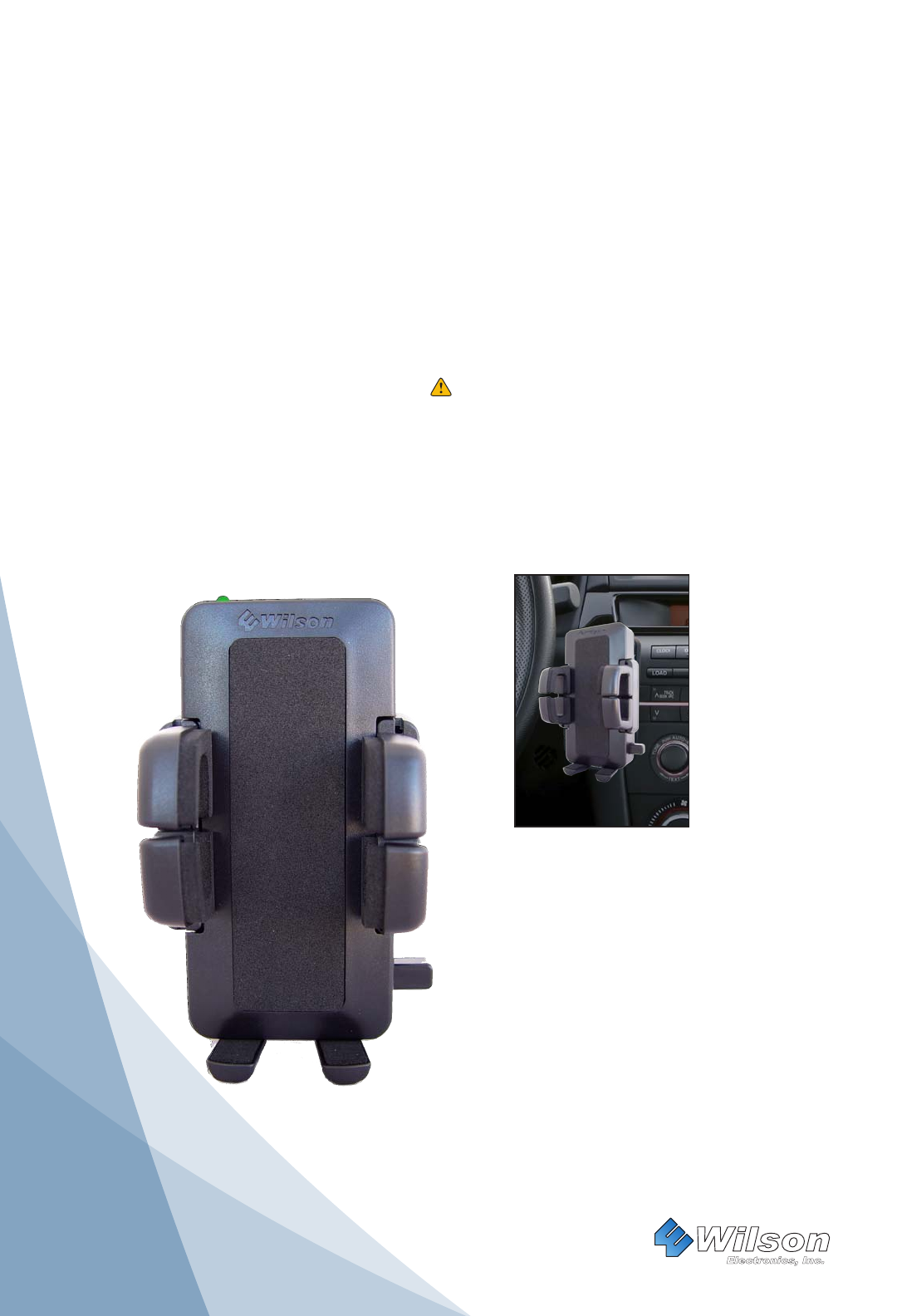
The phone must be placed in the U-Booster cradle at all times.
To achieve the best performance while the phone remains in the cradle, use a Bluetooth® headset for voice communications.
1
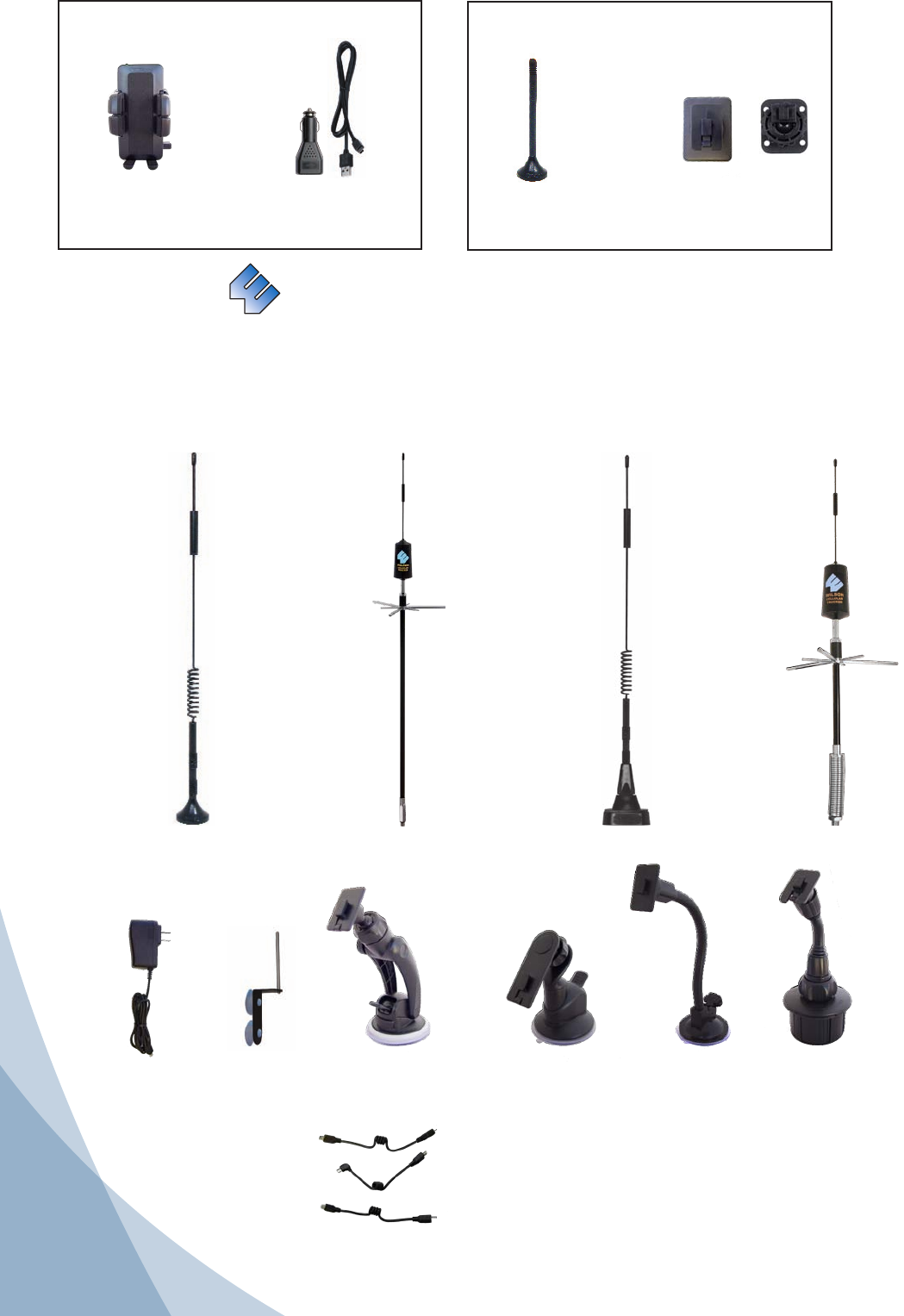
Inside this Package
Mini Magnet-Mount
antenna Vehicle Dash
Mounting Brackets
DC Plug-In
Power Supply
U-Booster™
Wireless Amplier/
Cradle
Wilson® Electronics, Inc.
Accessory Antennas & Mounts
Accessory Antenna Options
In addition to the convenient mini magnetic roof mount antenna included with your kit, Wilson
Electronics offers a wide variety of outside antennas to help you customize your amplier for a specic
application. All models shown below double the power to the cell site compared to the mini magnet
antenna. See your dealer or visit www.wilsonelectronics.com
AC Power Supply
901120
Gooseneck
Suction Cup
Crade Mount
901132
Cup Holder
Cradle Mount
901130
Adjustable
Suction Cup
Cradle Mount
901131
Low Prole
Suction Cup
Cradle Mount
Accessory Power Supply, Antenna Mounting ,Cradle Moutning and Charging Cable Options
301104
NMO Mount
Antenna
For permanent
vehicle roof mount
on cars and
pickup trucks.
Mounts on
Wilson NMO style
mounts: 901101,
901102, and
901103
301101
Trucker
Antenna
Designed for
mirror mounting
on large trucks.
Mounts on Wilson
3/8” mounts:
901104 and
901106
301103
12” Magnet
Mount Antenna
301133
RV
Antenna
Ideal for mounting
on non-metal
surfaces.
901128
Antenna
Window Mount
Included: if U-Booster® Kit is purchased
To order accessory items please call 800-204-4104 or visit www.wilsonelectronics.com
859967- Micro USB to Mini USB
859968- HTC USB to Mini USB
859966- Mini USB to Mini USB
2
General
Your Wilson amplier has been carefully engineered to signicantly improve the performance of
your phone. Together with an outside antenna, the amplier’s state-of-the-art circuitry is designed to
increase your phones signal to and from the cell site, up to 20 times greater than the phone alone. The
U-Booster™ reduces disconnects and dropouts and increases data communication rates on 2G and 3G
networks.
How it Works
With the phone in the cradle and while using a wireless Bluetooth headset (or wired hands free device)
the outside antenna collects the cell tower signal and sends it through its cable to the amplier located
inside the cradle. The signal is then boosted by the amplier and sent to the phone via the built-in
antenna inside the cradle. When the phone transmits, the signal is picked up by the antenna inside the
cradle, boosted by the amplier and broadcast back to the cell tower via the outside antenna.
Before Getting Started
This guide will help you properly install the Wilson U-Booster™ Dual-Band Wireless Amplier. It is important to read
through all of the installation steps prior to actual installation. If you do not understand the instructions contact
Wilson Technical Support at 866-294-1660.
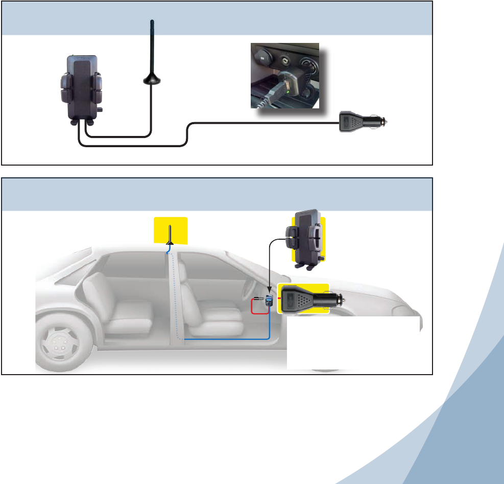
Wiring Diagram
Provides power to both the
amplier and charging for
the phone
Various
mounting
options
available
Exterior
Antenna
Vehicle Installation
Exterior antenna
communicates
with cell site
Amplier boosts
signal to and from
cell site
Provides power to both the
amplier and charging for
the phone with the correct
optional charging cable
Accessory Power Supply, Antenna Mounting ,Cradle Moutning and Charging Cable Options
To order accessory items please call 800-204-4104 or visit www.wilsonelectronics.com

3
OPTION 1
ADHESIVE BRACKET
1. Clean the area where the bracket is to be mounted with the
alcohol wipe provided. Allow to dry.
2. Peel the backing to expose the adhesive and press the bracket
onto the desired location in the vehicle. Note: be sure the tab is
positioned vertically, not horizontally.
3. Allow the adhesive to cure for 24 hours before you attach the
U-Booster™.
4. Once the cradle is attached, you can adjust the angle of the
adhesive bracket by applying gentle pressure to the top or bottom
of the U-Booster™. This option is designed to swivel when the
knurled nut is loosened, for greater adjustability of the U-Booster™
viewing angle. To lock bracket into position tighten large nut.
OPTION 2
ADHESIVE/SCREW SWIVEL BRACKET
This mount allows for adhesive mounting as well as more
permanent screw mounting. This option is designed to swivel
when the knurled nut is loosened, for greater adjustability of the
U-Booster™ viewing angle. For adhesive mounting, follow steps 1,
2 and 3 in option 1.
For screw mounting, use an ice pick or an awl to punch through
the adhesive and expose the four screw holes in the bracket. You
must provide the screws of an appropriate size for your particular
application. Using the bracket as a template, mark the locations
for the screws as shown, drill pilot holes, attach the bracket with
adhesive, and tighten all screws.
Vehicle Installation
1. Place Magnetic Roof Top Antenna
To receive the best cell signal, select a location for the outside antenna that is preferably in the center of the vehicle’s
roof, 12 inches away from any other antennas and free of obstructions, at least 8-12 inches from the rear or side
windows or sunroof.
The outside antenna must be installed vertically. Signal
performance will be degraded if the antenna is not
vertical.
The antenna cable is small yet strong enough that it may
be shut in most vehicle doors without damaging the cable.
For a more professional-looking installation, the antenna
cable may be run under the door seal. Carefully pull down
the door seal. Run the cable under the seal and push
the seal back into place. This prevents constant wear
and tear on the cable as the door opens and closes. The
antenna cable is small enough to easily tuck under the
door seal or plastic molding.
Magnet-Mount
Antenna Shown
Carefully
Pull Down
Door Seal
Run Cable
Under Seal
2. Attach the Mounting Bracket
Two mounting brackets are provided for attaching the U-Booster™ to your vehicle’s dash. Choose the appropriate
one for your application. See bracket specic mounting options below.
3. Attach the U-Booster™
Once you have installed your selected mount in the desired location, and waited 24 hours for adhesive to cure, attach
the cradle by aligning the rectangular hole on its back with the tab on the mount, grasping the sides of the cradle, slide
it downward approximately ¼ inch into place.
4
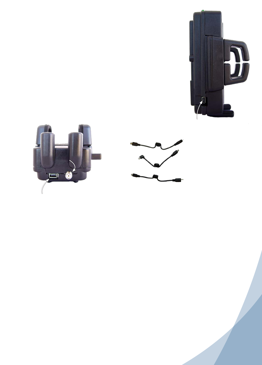
4. Powering up the Wilson U-Booster™ Amplier
Make sure the outside antenna cable is connected before
powering up the amplier.
Connect the mini-USB plug on the power cable to the U-Boosters
mini USB port located on the bottom of the U-Booster™ and insert the
adapter into the cigarette lighter outlet of your vehicle.
The U-Booster™ may remain on all the time. However, leaving the
U-Booster™ on in a vehicle when it is not running can discharge the
battery in a day or two.
A good option is to power the U-Booster™ through the ignition switch
so that the amplier is turned on and off with the vehicle. The 12 VDC
power source on many vehicles is shut off with the ignition key.
Note: With (optional) charging cables the U-Booster™ 5V power
supply provides charging current to the phone.
IMPORTANT: Do not power up the amplier unless the outside
antenna cable is attached to amplier.
WARNING: Use only the supplied Wilson power supply/connector to
power your U-Booster™.
U-Booster™ Power connector.
Connect to Wilson’s power supply
Antenna
connection
Phone charging connector port.
Connect to your phone with optional cables
3. Attach the U-Booster™
Once you have installed your selected mount in the desired location, and waited 24 hours for adhesive to cure, attach
the cradle by aligning the rectangular hole on its back with the tab on the mount, grasping the sides of the cradle, slide
it downward approximately ¼ inch into place.
Optional Phone Charging Cables
Understanding the Amplier Lights
Separation of U-Booster™ and the outside antenna is very important. In a vehicle, the metal roof acts as a
barrier and helps shield the two antennas from each other, preventing oscillation.
Oscillation can occur when the roof mounted antenna is too close to the U-Booster™ inside the vehicle. An
oscillation (or feedback) in an amplier is similar to when a microphone is too close to a speaker in a sound
system, resulting in a loud whistle. An oscillation in a cellular amplier, if allowed to occur, can affect nearby cell
sites’ ability to handle calls.
If the light turns red, an oscillation has occured and the amplier has powered down to protect the cell tower.
The outside roof mounted antenna needs to be moved farther from the U-Booster™. In a vehicle installation,
move the outside antenna on the roof of the car farther to the rear of the car, but at least 8-12 inches from the
rear or side windows or sunroof. Remove power from the U-Booster™ and reconnect power - this resets the
U-Booster™.
If the light is now green, the oscillation has stopped and the U-Booster™ is working. If the red light is still on,
move the outside antenna farther away and repeat the process.
In a vehicle, always use a magnet-mount or roof-mount antenna. Do not use a glass-mount antenna, as
oscillation may cause continuous shut-down of the U-Booster™.
859967- Micro USB to Mini USB
859968- HTC USB to Mini USB
859966- Mini USB to Mini USB
5
Installing a Wilson Outside Antenna in a Building
Follow the specic antenna instructions included with the outside antenna (sold separately except for certain kits). These
instructions assume that you are using a Wilson magnet-mount or mini magnet-mount antenna and the optional suction-
cup window bracket.
To receive the best signal, select a window on the side of your building where your outside signal is the strongest.
Attach the suction-cup bracket to the inside of a window so that the cable
will reach the amplier location. Place the bracket as high on the window as
possible for best performance.
Once the bracket is in place, attach the magnet base of the antenna to the
at surface of the bracket. Note: the antenna must be installed vertically.
Signal performance will be degraded if the antenna is not vertical.The
antenna cable is small enough to easily tuck under the door seal or plastic
molding.
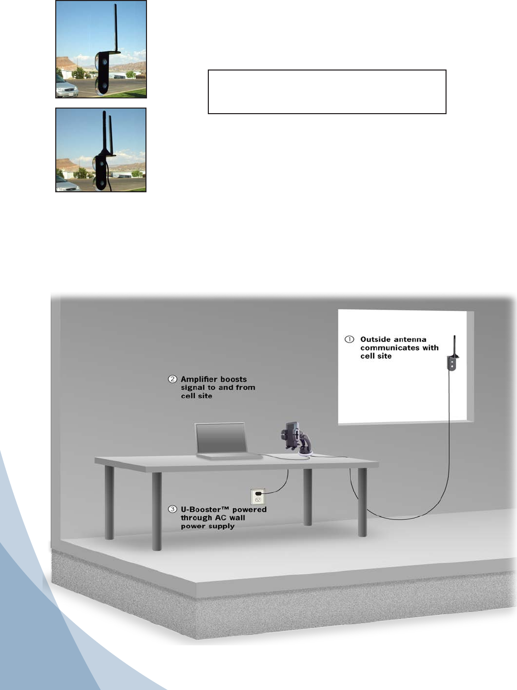
The Wilson U-Booster™ may be placed in any convenient indoor location, such as a desk or tabletop. The cell phone must be in the
cradle and a Bluetooth® headset used for voice communications.
Attaching the Antenna
Once you have selected the location for the U-Booster™, run the cable from the outside antenna and attach it to
the SMA connector on the bottom of the U-Booster™. Note: the U-Booster™ and the outside antenna must have a
minimum separation of 8 feet to prevent oscillation.
Installing the Wilson U-Booster Amplier in a Building
Building Installation
Suction cup Antenna Window Mount -not included-
Available from Wilson Electronics.
www.wilsonelectronics.com or call 800-204-4104

6
WARNINGS AND RECOMMENDATIONS
Warning: Do not plug in the power supply until the outside antenna cable is attached to the
amplier.
Warning: RF Safety: The U-Booster™ cradle/amplier must be installed with a separation of at
least 8 inches from all persons and must not be located in conjunction with any other
antenna or amplier.
Warning: RF Safety: The “outside antenna” must be either a Wilson Magnetic-Mount or Mini
Magnetic-Mount antenna and requires at least an 8 inch seperation distance from all
persons. Other outside antennas may be used provided that (a) they are not within
a building, structure, or vehicle (b) they are located with at least a 30 inch seperation
distance from all persons, (c) their gain less cable loss does not exceed 15 dBi, and (d)
they are not operating in conjunction with any other antenna or amplier.
Separation of U-Booster™ and outside antennas is very important. In a vehicle, the metal roof
acts as a barrier and helps shield the two antennas from each other, preventing
oscillation.
If the vehicle has a sunroof, it is important to keep the
outside antenna at least 8 inches from the edge of the
sunroof. This prevents the amplier from oscillating.
ABOUT WILSON ELECTRONICS
Wilson Electronics, Inc. has been a leader in the wireless
communications industry for nearly 40 years. The company designs and manufactures ampliers,
antennas and related components that signicantly improve cellular telephone signal reception and
transmission in a wide variety of applications, both mobile and in-building.
With extensive experience in antenna and amplier research and design, the company’s engineering
team uses a state-of-the-art testing laboratory, including an anechoic chamber and network analyzers,
to ne-tune antenna designs and performance. For its ampliers, Wilson uses a double-shielded RF
enclosure and cell site simulators for compliance testing.
All products are engineered and assembled in the company’s 55,000-square-foot headquarters in St.
George, Utah. Wilson has product dealers in all 50 states as well as in countries all over the world.
Troubleshooting
SYMPTOM: Green Light always OFF
1) Make sure that the power source is supplying power to
the U-Booster by checking that the light is on.
2) If the DC plug-in power supply is properly inserted,
but the plug’s light doesn’t come on, then check the
12 volts from the car socket, and check the fuse in
the DC plug-in power supply.
SYMPTOM: Red Light always ON
1) Make sure that the antenna connector is tight.
2) Place the outside antenna on its side (see picture).
Reset U-Booster™ power (off and back on) again.
The light should now be green (antenna was too
close). Turn U-Booster™ off and proceed to step 3.
3) Return the outside antenna to its upright position,
and move it further towards the rear of the vehicle,
(away from the U-Booster™) but no closer than 8
inches from a sunroof, rear or side windows. Power
U-Booster™ back on and recheck for a green light. If
light is still red, continue moving the antenna further
back and resetting the power until the light changes to
green and stays green. Remember to stay more than
8 inches away from a sunroof, rear or side windows.
4) If the light remains red, call Wilson Technical Support at 866-294-1660.

Wilson® Electronics, Inc. Phone: 866-294-1660 Fax: 435-656-2432 #815221 - U-Booster™
30-Day Money-Back Guarantee
All Wilson Electronics products are protected by Wilson’s 30-day money-back guarantee. If, for any reason, the performance of any product is not acceptable, simply return
the product directly to the reseller with a dated proof of purchase.
1-Year Warranty
Wilson Electronics ampliers are warranted for one (1) year against defects in workmanship and / or materials. Warranty issues may be resolved by returning the
product directly to the reseller with a dated proof of purchase.
Ampliers may also be returned directly to the manufacturer at the consumer’s expense, with a dated proof of purchase and a Returned Material Authorization (RMA)
number supplied by Wilson Electronics. Wilson shall, at its option, either repair or replace the product. Wilson Electronics will pay for delivery of the repaired or replaced
product back to the original consumer within the continental United States.
This warranty does not apply to any ampliers determined by Wilson Electronics to have been subjected to misuse, abuse, neglect, or mishandling that alters or
damages physical or electronic properties.
RMA numbers may be obtained by phoning Technical Support at 866-294-1660.
Operation is subject to the following two conditions: (1) This device may not cause interference, and (2) this device must accept any interference, including
interference that may cause undesired operation of this device.
Disclaimer: The information provided by Wilson Electronics, Inc. is believed to be complete and accurate. However, no responsibility is assumed by Wilson
Electronics, Inc. for any business or personal losses arising from its use, or for any infringements of patents or other rights of third parties that may result from its
use.Copyright © 2008 Wilson Electronics, Inc. All rights reserved.
#110788 - U-Booster™ Install Guide 2B5225 / 09.09.09
Amplier Specications
Dual Band
800/1900 MHz Specications
Model Number / Part Number 2B5225/805225
Connector SMA Female
Impedance (input/output) 50 ohms
Frequency 824-894 MHz / 1850-1990 MHz
1Passband Gain (nominal)
20 dB (typical) / 30 dB (maximum)
220 dB Bandwidth (nominal)
800 MHz (uplink/downlink) 43 MHz / 45 MHz (maximum)
1900 MHz (uplink/downlink) 112 MHz / 84 MHz (maximum)
Power output for single cell phone (uplink) 800 MHz 1900 MHz
CDMA 28.9 dBm 31.8 dBm
GSM 30.9 dBm 32.6 dBm
EDGE 30.9 dBm 31.9 dBm
WCDMA 30.13 dBm 31.4 dBm
AMPS 26.6 dBm
3,4Power output (uplink) for multiple
cell phones: Number of
cell phones
Maximum Power3
800 MHz 1900 MHz
2 27.3 dBm 21.5 dBm
323.8 dBm 17.9 dBm
4 21.3 dBm 15.4 dBm
5 19.4 dBm 13.5 dBm
617.8 dBm 11.9 dBm
Power output for single received channel (downlink) 800 MHz 1900 MHz
CDMA -.9 dBm 1.0 dBm
GSM -1.3 dBm 1.8 dBm
EDGE -1.3 dBm 2.1 dBm
WCDMA .32 dBm 2.3 dBm
AMPS -2.6 dBm
3,4Power output for multiple
received channels (downlink). The
maximum power is reduced by the
number of channels: Number of
channels
Maximum Power3
800 MHz 1900 MHz
2 -1.1 dBm 2.2 dBm
3 -4.7 dBm -1.4 dBm
4 -7.2 dBm -3.9 dBm
5 -9.1 dBm -5.8 dBm
6 -10.7 dBm -7.4 dBm
Noise Figure (typical) 3 dB nominal
Isolation > 40 dB
Power Requirements 5 V DC, 1 A
NOTES
1. Nominal gain is the maximum gain at any frequency in the passband.
2. Nominal bandwidth is the difference between two frequencies that are adjacent to the passband where the amplication is 20
dB lower than the passband amplication. One of the frequencies is lower than the passband and the other is higher.
3. The Manufacturer’s rated output power of this equipment is for single carrier operation. For situations when multiple carrier
signals are present, the rating would have to be reduced by 3.5 dB, especially where the output signal is re-radiated and can
cause interference to adjacent band users. This power reduction is to be by means of input power or gain reduction and not by
an attenuator at the output of the device.
4. Data is in accordance with IC spec RSS-131. The maximum power for 2 or more simultaneous signals will be reduced by 6 dB
for each doubling of the number of signals.