Wilson Electronics 806WB56 Bidirectional Amplifier Repeater User Manual
Wilson Electronics, LLC Bidirectional Amplifier Repeater Users Manual
Users Manual

AMPS
IN BUILDING
Bi-directional Amplier
#801102 (43dB Model)
#801103 (50dB Model)
#801104 (60dB Model)
FCC ID: PWO824WB56
IC: 4726A-824WB56
iDEN
IN BUILDING
Bi-directional Amplier
#804001 (43dB Model)
#804003 (50dB Model)
#804004 (60dB Model)
FCC ID: PWO806WB56
IC: 4726A-806WB56
Installation Guide
Wilson Electronics, Inc.
3301 E. Deseret Drive, St. George, Utah 84790
For additional technical support go to
www.wilsonelectronics.com
Phone: 1-866-294-1660 Fax: 1-435-656-2432
IN BUILDING
Wireless
The term “IC:” before the radio certification number only signifies
that Industry of Canada technical specifications were met.
2
3
1. PURPOSE OF THE AMPS/iDEN AMPLIFIER
The AMPS/iDEN Bi-directional Amplier improves RF coverage for areas in
which low signal strength or no signal is a problem.
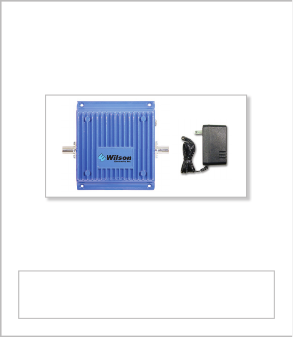
2. PACKAGE CONTENTS
2.1 AMPS/iDEN Bi-directional Amplier
2.2 AC-to-DC (110 volt) Power Supply
3. HOW THE AMPS/iDEN AMPLIFIER FUNCTIONS
The signal is received by the outside antenna from the cell site. The signal is then
AMPLIFIED and transmitted to your phone through the inside antenna. When
the phone transmits, the signal is received by the inside antenna and then
AMPLIFIED and transmitted to the cell site through the outside antenna.
The information provided by Wilson Electronics, Inc. is believed to be complete and accurate.
However, no responsibility is assumed by Wilson Electronics, Inc. for any business or per-
sonal losses arising from its use, or for any infringements of patents or other rights of third
parties that may result from its use.
Copyright © 2004 Wilson Electronics, Inc.

2
3
4. AMPLIFIER INSTALLATION (see illustration on 4-5)
4.1 Installing the Wilson Cellular Outside Antenna
4.1.1 Select a location on the roof using your AMPS/iDEN phone in test mode to
nd the best signal strength. (See leaet titled PHONE TEST MODES)
4.1.2 The Outside Antenna should be located in an area with at least a 3’ radius
clear of obstructions and other radiating elements.
NOTE: Mount the AMPLIFIER away from direct sunlight, excessive heat
and/or moisture. The amplifier needs proper ventilation.
DO NOT place the amplifier in an air-tight enclosure.
WARNING: The outside antenna used with this amplier must be xed-
mounted on an outdoor permanent structure with a separation of at least 20
feet from all persons during normal operation.
4.2 Installing The Amplier
WARNING: Connecting amplier directly to cell phone may damage phone.
4.2.1 Mount the AMPLIFIER on a wall or ceiling using #6 screws.
4.2.2 Connect the Outside Antenna to the AMPLIFIER side labeled “OUTSIDE
ANTENNA”.
4.2.3 Connect the Inside Antenna to the AMPLIFIER side labeled “INSIDE
ANTENNA”.
4.2.4 Verify that both the OUTSIDE and INSIDE antennas are connected be-
fore connecting the AC-DC power supply to the power outlet.
4.3 Installing The Wilson Cellular Inside Antenna
4.3.1 The Inside Antenna should be centered in the weak signal area. The
INSIDE ANTENNA should be at least 7’ from the ground.
WARNING: The inside antenna used with this amplier must be mounted
with a separation distance of at least 8 inches from all persons and must not be
co-located or operating in conjunction with any other antenna or amplier.
4.4 When covering large areas a splitter can be used to allow for more than one
inside antenna. Extension cables can also be used if the weak signal area is
located far from the location of the outside antenna.
NOTE: A minimum of 20’ coax extension is recommended for isolation
between antennas.
4
5
5. AMPLIFIER SPECIFICATIONS FOR AMPS 43dB, 50dB & 60dB MODELS
Part #: 801102 (43dB Model) & 801103 (50dB Model) & 801104 (60dB Model)
43dB 50dB 60dB
Frequency 824-849MHz Uplink 869-894MHz Downlink
Gain (up/down) (43dB/43dB) (50dB/50dB) (60dB/60dB)
Flatness (up/down) (+/- 4dB/+/-4dB) (+/- 4dB/+/-6dB) (+/- 4dB/+/-6dB)
Max RF (up/down) (+31.7dBm/+10dBm) (+31.7dBm/+10dBm) (+31.7dBm/+10dBm)
Noise Figure (down) (3dB nominal) (3dB nominal) (3dB nominal)
Isolation Uplink/Downlink More than 90dB
Power Consumption 13.8V, 1.5A

4
5
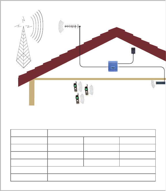
AMPLIFIER LAYOUT
KEEP A SEPARATION DISTANCE OF AT
LEAST 20ft HORIZONTAL AND 5ft VERTI-
CAL BETWEEN ANTENNAS
If using the Yagi Antenna, make sure the Yagi
is pointed AWAY from the inside antenna.
AMPLIFIER SPECIFICATIONS FOR iDEN 43dB, 50dB & 60dB MODELS
Part #: 804001 (43dB Model) & 804003 (50dB Model) & 804004 (60dB Model)
43dB 50dB 60dB
Frequency 806-821MHz Uplink 851-866MHz Downlink
Gain (up/down) (43dB/43dB) (50dB/50dB) (60dB/60dB)
Flatness (up/down) (+/- 4dB/+/-4dB) (+/- 4dB/+/-6dB) (+/- 4dB/+/-6dB)
Max RF (up/down) (+31.7dBm/+10dBm) (+31.7dBm/+10dBm) (+31.7dBm/+10dBm)
Noise Figure (down) (3dB nominal) (3dB nominal) (3dB nominal)
Isolation Uplink/Downlink More than 90dB
Power Consumption 13.8V, 1.5A
AMPS/iDEN AMPLIFIER PHYSICAL
SPECIFICATIONS
Connectors FME-Male 50 Ohms
Dimensions 5.5x4.3x1.4 (inch) or
14.0x10.8x3.5 (cm)
Weight 1.32 Pounds or 600G

6
7
6. OPTIONAL ACCESSORIES/ANTENNA OPTIONS
6.1 2-Way RF Splitter - allows for multiple inside antennas.
6.2 Coax Cable Extensions 50Ω (see chart on next page)
6.3 Antenna Options:
Inside Antenna Options Outside Antenna Option
301103 - Magnet Mount 301111 - Yagi
301106 - Stealth
301113 - Mini Magnet
6.4 N-Female To FME-Female Adapter - Adapts 9913 Coax to t the AMPS/
iDEN Bi-directional Amplier
6.5 Lightning Suppressor
WARNING: Lightning protection is recommended for all installations.
6.6 DC Power Cable
7. TECH SUPPORT
If you need further assistance with your installation:
1) Call us Toll-Free at 866-294-1660
2) E-mail tech support at tech@wilsonelectronics.com
3) Go to www.wilsonelectronics.com
Our Hours of Operation are: 8:00 AM – 4:30 PM (Mountain Time)
8. WARNINGS
WARNING: The outside antenna used with this amplier must be xed-mounted
on an outdoor permanent structure with a separation of at least 20 feet
from all persons during normal operation.
WARNING: The inside antenna used with this amplier must be mounted with a
separation distance of at least 8 inches from all persons and must not
be co-located or operating in conjunction with any other antenna or
amplier.
WARNING: Verify that both the Outside and Inside Antennas are connected before
plugging in the AC-DC power supply to the power outlet.
WARNING: Lightning protection is recommended for all installations.

6
7
951101 5’ Extension Cable RG 58
Low Loss Coax
(0.6 db loss)
951102 10’ Extension Cable RG 58
Low Loss Coax
(1.2 db loss)
951103 15’ Extension Cable RG 58
Low Loss Coax
(1.8 db loss)
951104 20’ Extension Cable RG 58
Low Loss Coax
(2.4 db loss) Used with the Yagi
Antenna - (N-Male to FME Female)
951108 20’ Extension Cable 9913
Ultra Low Loss Coax
Only use 9913 Low Loss Coax for
extensions 20’ or longer (0.8 db loss)
951105 30’ Extension Cable 9913
Ultra Low Loss Coax
(1.2 db loss)
951106 50’ Extension Cable 9913
Ultra Low Loss Coax
(2.0 db loss)
951107 100’ Extension 9913 Low
Loss Coax
(4.0 db loss)
951110 2’ Extension RG 58 Low
Loss Coax
(N-Male to FME Female)
Used with the Yagi antenna to help
nd the optimum signal strength (for
installation purposes only).
951113 2’ Extension 9913 Ultra
Low Loss Coax
(N-Male to N Male Ends)
(0.08 db loss) Jumper Coax - Can be
used to connect a splitter behind an
amplier.
EXTENSION CABLE CHART
RG 58 - FME connectors / 9913 - N connectors
Operation is subject to the following two conditions: (1) This device may not cause
interference, and (2) this device must accept any interference, including interference that
may cause undesired operation of this device.

8
For more options visit
www.wilsonelectronics.com
15 DAY
MONEY BACK
GUARANTEE
All Wilson products
have a 15 day
money back
guarantee with
Proof of Purchase
1 YEAR WARRANTY
The Wilson amplifier is warranted for one year against defects in workmanship
and/or materials and will be repaired or replaced, at the discretion of the manufac-
turer, to the original purchaser with dated proof of purchase or sales receipt.
If you have questions about your amplifier please call technical support
call 1-866-294-1660 or E-mail tech@wilsonelectronics.com
Most warranty cases can be handled by taking the amplifier and the re-
ceipt to the store where it was purchased. If inconvenient, the amplifier and a
copy of the receipt, may be sent to the factory, at purchasers expense, where
it may be repaired or replaced and returned shipping paid. Warranty does not
cover damages caused by abuse, misuse, and negligence.
ANTENNA OPTIONS