Wilson Electronics 824D Amps Bi-Directional Amplifier Direct User Manual manual
Wilson Electronics, LLC Amps Bi-Directional Amplifier Direct manual
manual
AMPS
DIRECT CONNECTION
AMPLIFIER
Part# 811101
FCC ID: PWO824D
IC: 4726A-824D
iDEN
DIRECT CONNECTION
AMPLIFIER
Part# 814001
FCC ID: PWO806D
IC: 4726A-806D
Installation Guide
Wilson Electronics, Inc.
3301 E. Deseret Drive, St. George, Utah 84790
For additional technical support go to
www.wilsonelectronics.com
Phone: 1-866-294-1660 Fax: 1-435-656-2432
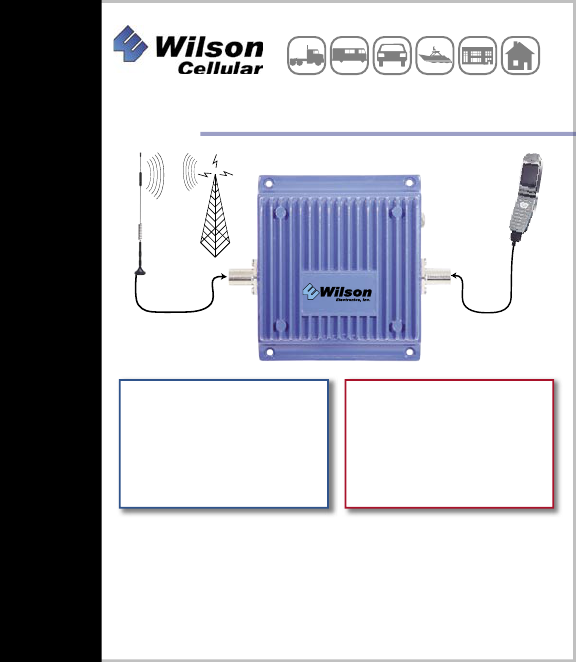
DIRECT CONNECTION
Vehicle & Building
The term “IC:” before the radio certification number only signifies
that Industry of Canada technical specifications were met.
2
3
1. PURPOSE OF THE DIRECT CONNECTION AMPLIFIER
The Direct Connection Bi-directional Amplifier improves RF coverage in areas
with no signal or low signal strength. Part# 811101 Amplifies the signal on
800MHz up to 3 watts and allows for the full benefit of the outside antenna on
1900MHz frequencies. Part# 814001 Amplifies the iDEN (Nextel) frequencies
up to 3 watts.
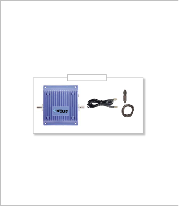
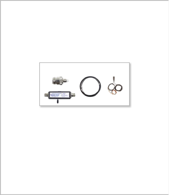
2. PACKAGE CONTENTS
2.1 Bi-directional Direct Connection Amplifier.
2.2 DC plug-in power supply with ON/OFF switch.
2.3 6ft. Adapter Extension Cable.
3. HOW THE DIRECT CONNECTION AMPLIFIER FUNCTIONS
When using 800 MHz the signal is received by the outside antenna from the cell site.
The signal is then AMPLIFIED and transmitted into your phone through the adapter
(sold separately). When the phone transmits, the signal is sent to the amplifier through
the adapter then AMPLIFIED and sent to the cell site through the outside antenna.
When using 1900MHz (PCS) the signal bypasses the amplifier’s circuitry while getting
full benefit from the outside antenna.
NOTE: Amplifier #814001 does not have a 1900MHz (PCS) bypass as iDEN
(Nextel) does not utilize this frequency.
Package Contents
AMPLIFIER
DC PLUG-IN
POWER SUPPLY
6FT ADAPTER
EXTENSION CABLE

2
3
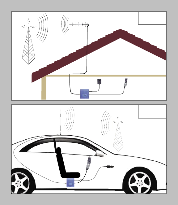
4. AMPLIFIER INSTALLATION (see illustration on pg.4)
4.1 Installing the
Wilson Cellular
Antenna
4.1.1 See antenna packaging for model specific instructions.
4.2 Installing The Amplifier
4.2.1 Select a suitable location to mount the AMPLIFIER.
• In vehicle installation - under the dash or vehicle seat
• In building installation - on a wall or ceiling
NOTE: Mount the AMPLIFIER away from direct sunlight, excessive heat and/
or moisture. The amplifier needs proper ventilation. DO NOT place
the amplifier in an air-tight enclosure.
4.2.2 Connect the outside antenna to the AMPLIFIER side labeled “OUTSIDE
ANTENNA”.
4.2.3 Connect the ADAPTER EXTENSION CABLE to the AMPLIFIER side
labeled “CELLULAR PHONE”.
4.2.4 An external antenna adapter is required (sold separately) to connect the
AMPLIFIER to the cellphone. External antenna adapters connect directly to
the antenna extension cable.
4.2.5 Connect the DC power supply to the AMPLIFIER. Verify that both the
OUTSIDE ANTENNA and the ADAPTER EXTENSION CABLE
are connected before powering up the AMPLIFIER.
NOTE: Visit our website at www.wilsonelectronics.com for the latest adapter
cross reference chart. If your phone’s adapter is not available from your
retailer contact us at 1-866-294-6996 and we will help you locate one in
your area. For further assistance contact our technical support Toll-Free
at 866-294-1660.
NOTE: iDEN Antennas are recommended for iDEN Amplifier 814001.
The information provided by Wilson Electronics, Inc. is believed to be complete and accurate.
However, no responsibility is assumed by Wilson Electronics, Inc. for any business or per-
sonal losses arising from its use, or for any infringements of patents or other rights of third
parties that may result from its use.
Copyright © 2003 Wilson Electronics, Inc.
4
5
In-Building
Installation
Mobile
Installation
4
5
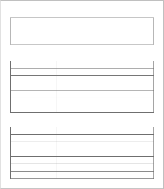
5. AMPLIFIER SPECIFICATIONS
DIRECT CONNECTION AMPLIFIER PHYSICAL SPECIFICATIONS
Connectors FME-Male 50 Ohms
Dimensions 5.5x4.3x1.4 (inch) or 14.0x10.8x3.5 (cm)
Weight 1.32 Pounds or 600G
AMPS #811101 AMPLIFIER SPECIFICATIONS
Frequency 824-849MHz Uplink 869-894MHz Downlink
Gain (up/down) Cell Site Controlled-Max 10/10
Flatness (up/down) (+/- 2dB / +/-2dB)
Max RF (up/down) (+35dBm/+15dBm)
Noise Figure (down) (3.5dB@881MHz)
Isolation Uplink/Downlink 90dB
Power Consumption 1.5A@12V
iDEN #814001 AMPLIFIER SPECIFICATIONS
Frequency 806-821MHz Uplink 851-866MHz Downlink
Gain (up/down) Cell Site Controlled-Max 10/10
Flatness (up/down) (+/- 2dB / +/-2dB)
Max RF (up/down) (+35dBm/+15dBm)
Noise Figure (down) (3.5dB@881MHz)
Isolation Uplink/Downlink 90dB
Power Consumption 1.5A@12V
6
7
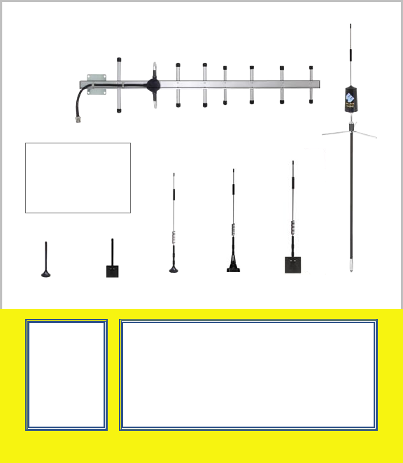
6. OPTIONAL ACCESSORIES/ANTENNA OPTIONS
6.1 Coax Cable Extensions 50Ω (see chart on pg.7)
6.2 Antenna Options (see chart on pg. 8)
6.3 N-Female To FME-Female Adapter - Adapts 9913 Coax to the
811101/814001 Bi-directional Amplifier.
6.4 Lightning Suppressor (In-Building application)
WARNING: Lightning protection is recommended for all In-Building
installations.
6.5 Hardwire Power Supply Kit.
8. WARNINGS
WARNING: Verify that both the outside antenna and adapter extension cable are
connected before powering up the AMPLIFIER.
WARNING: (MOBILE ONLY) The outside antenna used with this ampli-
fier must be mounted with a separation distance of at least 8 inches from all
persons and must not be co-located or operating in conjunction with any other
antenna or amplifier. Use of a cellular amplifier with antenna gains higher than
5.12dBi is in violation of FCC regulations for which the offender is fully liable.
All Wilson Mobile Antennas are 5.12dBi or less.
WARNING: (IN-BUILDING ONLY) Lightning protection is recommended for all
in-building installations.
WARNING: (IN-BUILDING ONLY) When using in-building, the outside antenna
must be fixed-mounted on an outdoor permanent structure with a separation of at
least 20 feet from all persons during normal operation.
Optional Accessories

6
7
7. TECH SUPPORT
If you need further assistance with your installation:
1) Call us Toll-Free at 866-294-1660
2) E-mail tech support at tech@wilsonelectronics.com
3) Go to www.wilsonelectronics.com
Our Hours of Operation are: 8:00 AM – 4:30 PM (Mountain Time)
951101 5’ Extension Cable RG 58
Low Loss Coax
(0.6 db loss)
951102 10’ Extension Cable RG 58
Low Loss Coax
(1.2 db loss)
951103 15’ Extension Cable RG 58
Low Loss Coax
(1.8 db loss)
951104 20’ Extension Cable RG 58
Low Loss Coax
(2.4 db loss) Used with the Yagi
Antenna - (N-Male to FME Female)
951108 20’ Extension Cable 9913
Ultra Low Loss Coax
Only use 9913 Low Loss Coax for
extensions 20’ or longer (0.8 db loss)
951105 30’ Extension Cable 9913
Ultra Low Loss Coax
(1.2 db loss)
951106 50’ Extension Cable 9913
Ultra Low Loss Coax
(2.0 db loss)
951107 100’ Extension 9913 Low
Loss Coax
(4.0 db loss)
EXTENSION CABLE CHART (RG 58 - FME connectors / 9913 - N connectors)
Operation is subject to the following two conditions: (1) This device may not cause interference, and (2) this
device must accept any interference, including interference that may cause undesired operation of this device.
Leaving the amplifier on in an unused vehicle for days may drain your battery. This can be avoided by
plugging into an ignition switched outlet or by using the small white switch located on the power supply.
8
For more options visit
www.wilsonelectronics.com
Outside Antenna Options
Pictures Are Not To Scale
Not All Outside Antenna
Options Are Shown
Questions?
1-866-294-1660
www.wilsonelectronics.com
15 DAY
MONEY BACK
GUARANTEE
All Wilson products
have a 15 day
money back
guarantee with
Proof of Purchase
1 YEAR WARRANTY
The Wilson amplifier is warranted for one year against defects in workmanship
and/or materials and will be repaired or replaced, at the discretion of the manufac-
turer, to the original purchaser with dated proof of purchase or sales receipt.
If you have questions about your amplifier please call technical support
call 1-866-294-1660 or E-mail tech@wilsonelectronics.com
Most warranty cases can be handled by taking the amplifier and the re-
ceipt to the store where it was purchased. If inconvenient, the amplifier and a
copy of the receipt, may be sent to the factory, at purchasers expense, where
it may be repaired or replaced and returned shipping paid. Warranty does not
cover damages caused by abuse, misuse, and negligence.