Windigo Systems PBTHSTF2C2E Bluetooth Earphone User Manual
Windigo Systems Bluetooth Earphone Users Manual
Users Manual
Confidential Page 1 5/8/2003
2210 O’Toole Ave. #200, San Jose, Ca. 95131
Tel: 408-576-1770 Fax: 408-576-1790
2210 O'Toole Ave #200
San Jose, CA 95131
TEL : 408.576.1770
FAX : 408.576.1790
info@windigosys.com
http://www.windigosys.com/
Windi
g
o Products
Windigo Bluetooth(TM) Headset User manual
(Mini Headset Module)
PBTHSTA2C2M
Ver.1.2
Wednesday, May 07, 2003

Confidential Page 2 5/8/2003
2210 O’Toole Ave. #200, San Jose, Ca. 95131
Tel: 408-576-1770 Fax: 408-576-1790
FEDERAL COMMUNICATIONS COMMISSION
This device complies with Part 15 of the FCC Rules. Operation is subject to
the following two conditions:(1) this device may not cause harmful
interference, and (2) this device must accept any interference received,
including interference that may cause undesired operation.
NOTE
This equipment has been tested and found to comply with the limits for a
Class B digital device, pursuant to Part 15 of the FCC Rules. These limits are
designed to provide reasonable protection. This equipment generates, uses
and can radiated radio frequency energy and, if not installed and used in
accordance with the instructions, may cause harmful interference to radio
communications. However, there is no guarantee that interference will not
occur in a particular installation If this equipment does cause harmful
interference to radio or television reception, which can be determined by
turning the equipment off and on, the user is encouraged to try to correct the
interference by one or more of the following measures:
-Reorient or relocate the receiving antenna.
-Increase the separation between the equipment and receiver.
-Connect the equipment into an outlet on a circuit different from that to which
the receiver is connected.
-Consult the dealer or an experienced radio/TV technician for help.
Shielded interface cables must be used in order to comply with emission
limits.
Changes or modifications not expressly approved by the party responsible for
compliance could void the user‘s authority to operate the equipment.
Confidential Page 3 5/8/2003
2210 O’Toole Ave. #200, San Jose, Ca. 95131
Tel: 408-576-1770 Fax: 408-576-1790
1. Introduction
Bluetooth profile K-6 gives an implementation guideline for Bluetooth headset
application, which includes two functions: Bluetooth headset and Bluetooth
audio gateway. Generally headset profile will be implemented in headset, and
audio gateway will be implemented in cellular phone, PBX or other
communication devices. Windigo systems has developed a fully Bluetooth
V1.1 compliant headset module.
This manual will explain the basic headset operation instruction to our
customers.
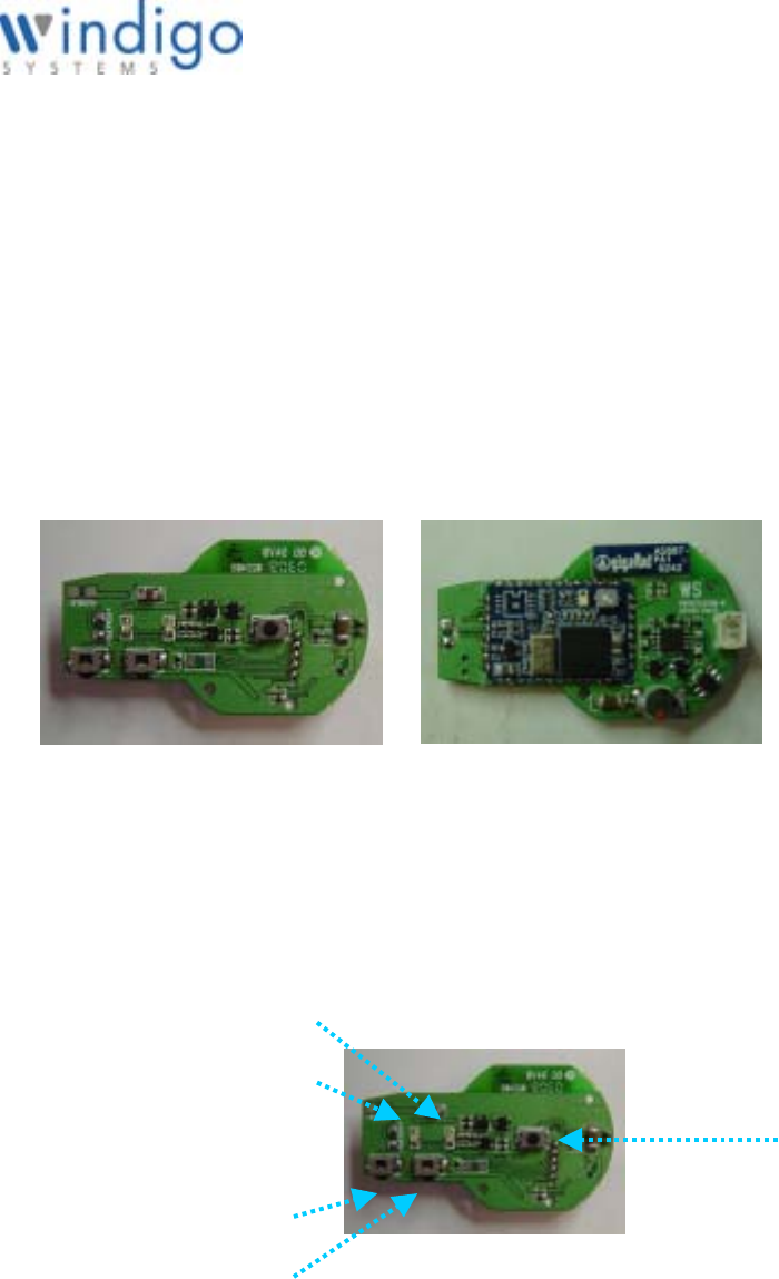
2. A glimpse at the headset
Figure 1 illustrates the reference headset and cellular phone.
Figure 1. Windigo Bluetooth Headset Reference Design
The headset module includes an amber LED, a blue LED, three buttons, and
embedded audio connections and charging contact, these elements are
illustrated in figure 2.
Figure 2. Key elements on Windigo Bluetooth Headset
Both amber LED and blue LED are used to indicate various operation status
for the headset, such as pairing, connecting, talking…etc.
Talk Button
Amber LED
Blue LED
Volume Up
Volume Down
Fig. 1.a PBTHSTA2C2M – Top View Fig1.b PBTHSTA2C2M- Bottom View

Confidential Page 4 5/8/2003
2210 O’Toole Ave. #200, San Jose, Ca. 95131
Tel: 408-576-1770 Fax: 408-576-1790
The three buttons are used to initialize various operations, such as activating
the headset, turning off the headset, pairing, connecting, etc.
Audio connections are used to connect an external microphone and speaker.
Windigo Bluetooth Headset must be paired with an audio gateway before it is
fully functional. Please refer to the audio gateway user manual on how to
initialize and operate the audio gateway and its various functions.
3. Getting start
Step 1:
Be sure the headset battery is fully charged before the first time use.
(Charging time is about 2 hours)
Step 2:
Enter into pairing (discoverable and connectable) mode
During headset transportation, headset is on idle (deep sleep) mode to
conserve battery power. While in this idle mode, both blue and amber LEDs
are off. To enable the pairing mode, press and hold the talk button until blue
and amber LED flash alternatively, and a PAIR tone will be heard. This press
and hold time is about 5 seconds. Please be noted that before blue and
amber LED flash alternatively, either blue or amber LED will flash shortly
depends on the battery status, and an ON tone will be heard. So in order to
enter into pairing mode correctly, please still hold the talk button. After the
PAIR tone is heard, and blue and amber LED flash alternatively, then release
the button.
Note:
1. Default headset name is BTHS03, and pin code is 0000
2. Pairing feature is used to establish the relationship between headset and
audio gateway. Any given headset can only talk with the paired audio
gateway after a successful pairing session.
3. Pairing mode can be cancelled by pressing and holding the talk button for
about 3 seconds, until both amber LED and blue LED are off, and the OFF
tone is heard. Then the headset is put into idle mode again.
4. Follow the instruction for specific audio gateway to perform the pairing. If
the headset has been paired with audio gateway successfully, the headset
will enter into standby (connectable only) mode. During this mode, blue
LED will flash at 1-second interval if battery is full, and amber LED is off.
Otherwise, if battery is low, then amber LED will flash at 1-second interval
and blue LED will be off.
Step 3:
Now the headset is ready to use. The headset will ring whenever there is an
incoming call.

Confidential Page 5 5/8/2003
2210 O’Toole Ave. #200, San Jose, Ca. 95131
Tel: 408-576-1770 Fax: 408-576-1790
Step 4:
Answering the incoming call.
When the headset is ringing, user can pick up the call by pressing the talk
button once shortly.
Note:
Make sure the cellular phone has been configured correctly so an
incoming call is transferred to the headset via Bluetooth link.
Step 5:
Initiate connection to audio gateway
Normally the headset will stay in standby mode, if user wants to initiate a
connection to the audio gateway, for example, voice dial with a suitable
cellular phone, user can press the talk button once. While in this mode, the
blue LED (or amber LED if battery low) will flash quickly for twice, then after 1
second, blue LED (or amber LED if battery low) will flash twice quickly again.
In other words, the LED will flash quickly twice every 1 second. Once the
connection between headset and audio gateway is established, the blue LED
(or amber LED if battery low) will flash four times quickly after 3 second.
Step 6:
Adjusting the volume
Once the audio connection is established, User can adjust the volume by
pressing volume button shortly to adjust the volume to louder or softer.
Step 7:
Mute/un-mute the microphone during talking.
User can mute/un-mute the microphone temporally by depressing either
volume button for about 3 seconds. If the microphone is muted, to un-mute
the microphone, user can depress either volume button for 3 seconds.
4. Summary of the LED display
No display
Headset is in idle mode
If blue LED is working, means battery is fully
If amber LED is working, means battery runs low
LED flashes at 1-seconds interval
Headset is in standby (connectable) mode
LED flashes twice quickly at 1-seconds interval
Headset is trying to make an audio connection to phone. This most
probably will happen when user wants to make a voice dial.
LED flashes four times quickly every 1-second interval

Confidential Page 6 5/8/2003
2210 O’Toole Ave. #200, San Jose, Ca. 95131
Tel: 408-576-1770 Fax: 408-576-1790
Headset is in talking (SCO connected) mode
5. Summary of button operation
Short press talk button (hold time less than 1 seconds)
When headset is in standby mode, this will put headset into master mode
When headset is in master mode, this will put headset into idle mode
When headset is in talking mode, this will put headset into standby mode
Short press volume button (hold time less than 1 seconds)
When headset is not in talking mode, this takes no effect.
When headset is in talking mode, this will adjust headset volume
Press and hold talk buttons for 3 seconds
When headset is in idle mode, this will put headset into standby mode, in
other words, this will turn on headset
When headset is not in idle mode, this will turn off headset
Press and hold volume button for 3 seconds
When headset is not talking mode, this takes no effect on headset’s status
When headset is in talking module, this will toggle microphone mute and
un-mute.
Press and hold talk buttons for 5 seconds
When headset is in idle mode, this will put headset into pairing mode.
When headset is not in idle mode, this takes no effect on headset status.
6. Summary of status transition
Both amber and blue LEDs are turned off
Amber LED and blue LED flash alternatively
Blue LED is turned off, and amber LED flashes
Blue LED flashes, and amber LED is turned off
Normally the headset will stay in standby mode unless user initializes shutdown
operation.

Confidential Page 7 5/8/2003
2210 O’Toole Ave. #200, San Jose, Ca. 95131
Tel: 408-576-1770 Fax: 408-576-1790
User Interface State Diagrams for three buttons design
Power Off
Deep Sleep
Power Applied
Paring
Long Talk or not paired
Long Talk
Standby
Long Talk
Connecting
Long Talk
Paired
Long Talk
Long Talk
Long Talk
Timeout
Connected
RFCOMM
Talking
Mic Muted
Long Volume
Long Volume
Talk
Talk
Long Talk
Long Talk
Long Talk continuously from Deep Sleep
7. Key parameters settings
Here lists all the parameters preset to Windigo Headset module, and also
please be noted that these parameters can be customized based on
customers preference.

Confidential Page 8 5/8/2003
2210 O’Toole Ave. #200, San Jose, Ca. 95131
Tel: 408-576-1770 Fax: 408-576-1790
A. Buttons numbers: 3
B. Long press timer: 1 second
C. LED on time: 20 ms
D. LED quick flash interval: 200 ms
E. LED flash interval: 1 second
F. LED quick flash times for standby: 1
G. LED quick flash times for standby with ACL: 1
H. LED quick flash times for connecting: 2
I. LED quick flash times for talking: 4
J. LED quick flash times for ON/OFF: 5
K. LED flash interval for paring: 128 ms
L. Threshold for high voltage alert: 3.55 V
M. Threshold for low battery alert: 3.50 V
N. Threshold for turning off headset: 2.80 V
O. Battery monitor interval: 32 seconds
P. Connecting mode timeout: 10 seconds
Q. Default audio input gain: 29
R. Default audio output gain: 10
S. Default pin code: 0000
T. Default headset name: BTHS03
U. Pairing mode timeout: 60 seconds