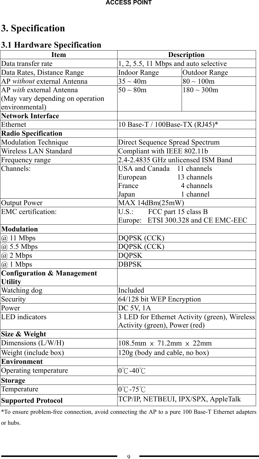
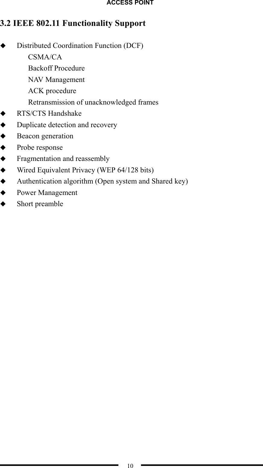
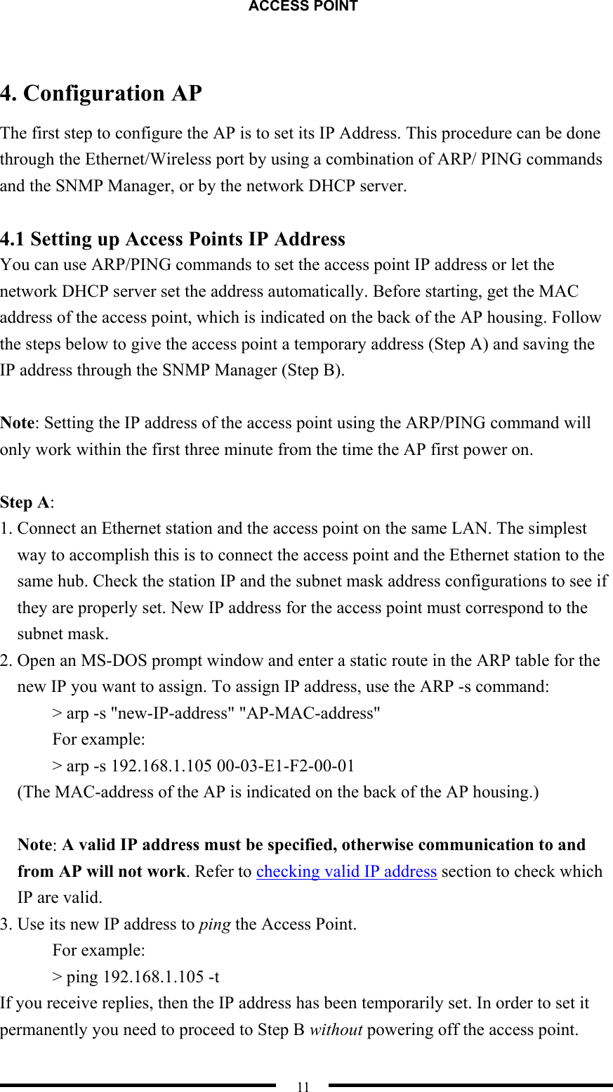
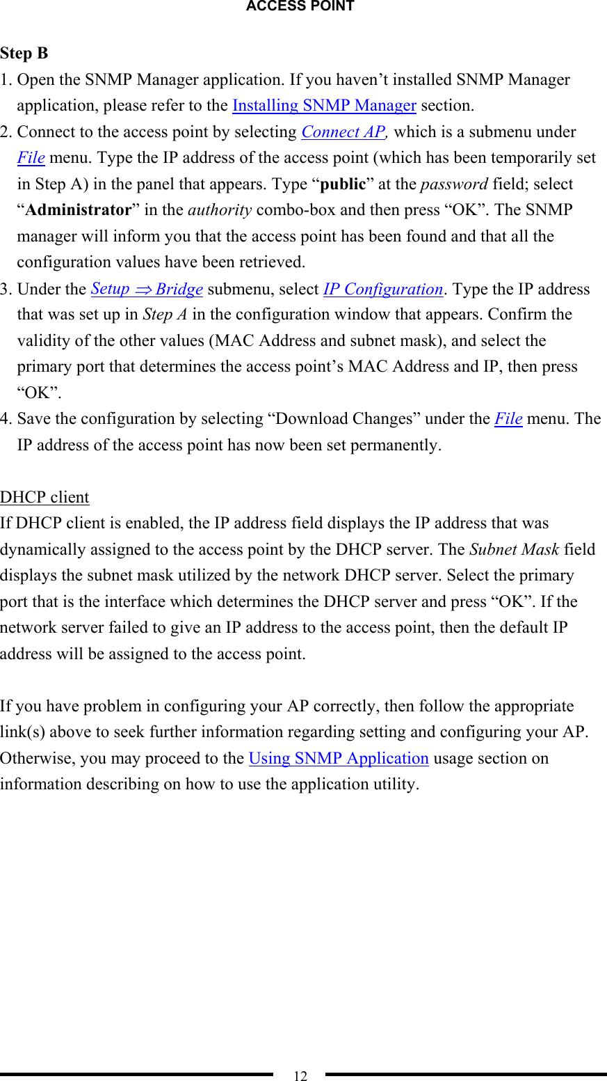
Winmate 1200 Access Point User Manual

WINMATE Communication INC. Access Point Users Manual

Users Manual

ACCESS POINT  i           User Guide Access Point
ACCESS POINT  ii Table of Contents  1. INTRODUCTION ................................................................................ 1 1.1 PRODUCT FEATURES .............................................................................................1 1.2 NETWORK OVERVIEW ...........................................................................................2 1.2.1 Infrastructure Mode ......................................................................................2 1.2.2 Microcells and Roaming ...............................................................................3 1.3 NETWORK SERVICE SET IDENTIFICATION (SSID) OVERVIEW................................4 1.4 CHANNEL SERVICES OVERVIEW ............................................................................5 1.5 REQUIREMENT FOR A WIRELESS CONNECTION.......................................................5 2. INSTALLATION AP ............................................................................ 6 2.1 PACKAGE CONTENTS .............................................................................................6 2.2 NOTICE .................................................................................................................6 2.3 INSTALLATION DIAGRAM ......................................................................................6 2.4 PHYSICAL DESCRIPTION........................................................................................7 2.5 CONNECTING TO THE NETWORK ...........................................................................7 2.6 AP CONFIGURATION (INSTALL THE SNMP MANAGER) ........................................7 2.7 DEFAULT SETTING.................................................................................................8 3. SPECIFICATION ................................................................................. 9 3.1 HARDWARE SPECIFICATION...................................................................................9 3.2 IEEE 802.11 FUNCTIONALITY SUPPORT .............................................................10 4. CONFIGURATION AP ...................................................................... 11 4.1 SETTING UP ACCESS POINTS IP ADDRESS ...........................................................11 5. INSTALLING SNMP MANAGER.................................................... 13 5.0.1 USING SNMP APPLICATION ............................................................................14 5.1 FILE MENU..........................................................................................................15 5.1.1 Connection to Access Point ........................................................................16 5.1.2 Find Access Point .......................................................................................17 5.2 SETUP MENU.......................................................................................................19 5.2.1 Bridge..........................................................................................................20 5.2.2 IP Configuration .........................................................................................21
ACCESS POINT  iii 5.2.3 Wireless LAN...............................................................................................22 5.2.4 Privacy Options ..........................................................................................23 5.2.5 Operational Settings ...................................................................................24 5.2.6 Advance Operational Setting ......................................................................26 5.2.7 Authorized MAC addresses.........................................................................29 5.2.8 SNMP Traps ................................................................................................30 5.2.9 Authorization ..............................................................................................31 5.3 COMMANDS MENU .............................................................................................32 5.4 INFORMATION MENU...........................................................................................33 5.4.1 Wireless Statistics........................................................................................34 5.4.2Ethernet Statistics ........................................................................................35 5.5 TRAP MENU ........................................................................................................36 5.6 NETWORK MENU ................................................................................................38 5.7 WINDOW MENU ..................................................................................................40 5.8 HELP MENU ........................................................................................................41 6. TUTORIAL ........................................................................................ 42 6.1 PACKET FRAGMENTATION ...................................................................................42 6.2 ENCRYPTION .......................................................................................................43 Authentication Type .............................................................................................44 How is encryption key generated?.......................................................................44 6.3 SUBNETTING .......................................................................................................45 7. TROUBLESHOOTING...................................................................... 46 7.1 CHECKING VALID IP ADDRESSES ........................................................................49 7.2 CONNECTION TROUBLESHOOTING ......................................................................50 7.3 RESETTING THE ACCESS POINT ...........................................................................51 7.4 ENCRYPTION TROUBLESHOOTING .......................................................................52 7.5 TROUBLESHOOTING CHECK TABLE .....................................................................53 8. FAQ..................................................................................................... 54 9. WLAN GLOSSARY........................................................................... 56 FEDERAL COMMUNICATIONS COMMISSION INTERFERENCE STATEMENT......... 60
ACCESS POINT  iv Copyright © 2002 Manufacturer all rights reserved.  The information in this document is subject to change without notice. The statements, configurations, technical data, and recommendations in this document are believed to be accurate and reliable, but are presented without express or implied warranty. Users must take full responsibility for their applications of any products specified in this document. The information in this document is proprietary to Manufacturer.  Manufacturer reserves the right to make revisions to this publication without obligation to notify any person or entity of any such changes.    Trademarks  Microsoft, Windows 98, Windows ME, Windows 2000, Windows XP are trademarks or registered trademarks of Microsoft Corporation.  Atmel and Atmel logo are trademarks or registered trademarks of Atmel Corporation.  All other trademarks and registered trademarks are the property of their respective owner
ACCESS POINT  1 1. Introduction This user guide provides an overview of the Wireless LAN Technology and instruction for using the Access Point. Actually, Wireless LAN is a flexible data communication system implemented as an extension to, or as an alternative for, a wired LAN within a building or campus. Using electromagnetic waves, WLANs transmit and receive data over the air, minimizing the need for wired connections.  Overall, we hope this document is helpful to give users a Clear View on the Access Point and a better understanding of WLAN Technology.   1.1 Product Features  Flexible and standards-based (IEEE802.11b) interoperability.  64/128bits WEP key encryption for security.  MAC address registration function for security.  Communication between the Ethernet LAN and the wireless LAN.  AppleTalk protocol compatible.  Automatic Rate Fallback.  Association, Re-association and Disassociation.  Support three Operational Modes (Access Point, AP Client, Wireless Bridge).  Support Simple Network Management Protocol (SNMP).  DHCP Client-Default Gateway.  IP Filtering.
ACCESS POINT  2 1.2 Network Overview  1.2.1 Infrastructure Mode In an infrastructure network, the wireless device (such as Access Point) links the WLAN to the wired network to offer users more mobilities in movement and resources sharing within the network service area. It enables users to have freedom from network cabling.   Figure 1 - Infrastructure mode
ACCESS POINT  3  1.2.2 Microcells and Roaming WLANs use cells, called microcells, similar to the cellular telephone system to extend the range of wireless connectivity. At any point in time, a mobile PC equipped with a WLAN adapter is associated with a single access point and its microcell, or area of coverage. Individual microcells overlap to allow continuous communication within wired network. They handle low-power signals and allow users to roam through a given geographic area.    Figure 2 - Handling of WLAN connection between APs
ACCESS POINT  4    1.3 Network Service Set Identification (SSID) Overview   On a wireless network, a mobile user can roam freely within the service area of the Access Point with the same service Set Identification SSIDs without losing connection to the wired network. In order for a mobile unit to roam seamlessly from one Access Point to another, the SSIDs of all Access Points and the wireless LAN cards must be the same.  Assigning SSIDs, can provide the following security:   To avoid different user-groups from accessing network resources other than their own.   Ensure each user-group has access within its own network.   Assure different user-group has the same access to Ethernet segment.   Figure 3 illustrates the use off SSIDs in an environment containing multiple infrastructure network configured to communicate in the same Ethernet segment. SSIDs assure the 3 users of Group A can only access each other, but not other infrastructure, such as Group B.   Figure 3 – SSID Assignments
ACCESS POINT  5 1.4 Channel Services Overview The Direct Sequence Spread Spectrum (DSSS) modulation has the effect of suppressing radio frequency interference in the same frequency bands. The IEEE 802.11b DSSS service is a channelized service, listed as Table 1.  Table 1 - Channel Usage by Country Country  Channels Used by the Access Point United States  1 through 11 Canada    1 through 11 Europe    1 through 13 France  10 through 13 Spain  10 through 11 Japan 14  1.5 Requirement for a wireless connection To install an Access Point, the hardware requirements are:   A supported LAN protocol stack (IPX/SPX or TCP/IP or AppleTalk)   For a 100 Base-TX / 10 Base-T Ethernet connection, a modular data cable with a dual twisted pair cable terminated with a male RJ-45 modular jack
ACCESS POINT  6 2. Installation AP 2.1 Package contents Before using the Access point, please make sure that all the items listed below are present in your package.   Wireless Access Point   5V DC power adapter     Installation CD   Quick Installation Guide If any items are missing or damaged, please contact your dealer immediately.  2.2 Notice   1.  Keep the Number of Wall and ceilings to a minimum. Each of Wall or Ceiling will reduce 20-30% transmission range. 2.  Make sure having the direct line among the Client WLAN card. 3.  Keep your product away from electronic devices 4.  Make sure that the antenna is positioned for best reception 5.  Building Material make a difference. Normally a solid metal door or aluminum studs may have a negative effect on range.  2.3 Installation Diagram   Figure 4 - Installation Diagram
ACCESS POINT  7 2.4 Physical Description  Figure 5 - Access Point Diagram  To install your Access Point, plug the power cord into the Access Point. When power is applied and the network system has been loaded, please refer to Table 2 for the LED activity:  Table  2 LED   Activity  Description 1st  Flashing (Green)  Communicating with the wireless LAN 2nd  On (Green) Flashing (Green) LAN connection is active Communicating with the LAN 3rd  On (Red)  Power is on  2.5 Connecting to the Network After installing the AP you can connect to the network when you have completed network configuration of your wireless adapter.  2.6 AP Configuration (Install the SNMP Manager) If you want to configure the AP (e.g.: Setting the AP’s IP address*), please refer to Configuration AP and Installing SNMP Manager section. The electronic user manual will guide you on how to install the Access Point SNMP Manager and configure the AP through the Access Point SNMP Manager.   * You can connect to network without setting the AP’s IP address 3rd – PWR (POWER lamp) 2nd – LAN (LAN lamp) 1st – WLAN (Wireless LAN lamp)
ACCESS POINT  8 2.7 Default Setting  Functions  Default Options IP Address  192.168.100.2  Subnet Mask  255.255.255.0  Gateway  0.0.0.0  DHCP  Disable Enable/ Disable Access Point Name  AP-xxxxxx*  ESSID  AP-xxxxxx*  SSID Broadcasting  Enable Enable/ Disable Channel  10  1~14 (Depend on Regulatory Domain) Fragmentation Threshold  2346  256 ~ 2346 RTS Threshold  2346  0 ~ 2347 Rates  1/ 2/ 5.5/ 11  1, 2, 5.5, 11 Mbps Authentication Type  Both  Open System/ Shared Key/ Both Preamble Type  Long Short/ Long Rx Antenna  Diversity  Left/ Right/ Diversity Tx Antenna  Left  Left/ Right/ Diversity Operational Mode  Access Point  Access Point/ Access Point Client/ Wireless Bridge User Password  public  Administrator Password  public  * Where xxxxxx are the last 6 digits of your devices MAC address.
ACCESS POINT  9 3. Specification 3.1 Hardware Specification Item Description Data transfer rate  1, 2, 5.5, 11 Mbps and auto selective Data Rates, Distance Range  Indoor Range  Outdoor Range AP without external Antenna  35 ~ 40m  80 ~ 100m AP with external Antenna (May vary depending on operation environmental) 50 ~ 80m  180 ~ 300m Network Interface   Ethernet  10 Base-T / 100Base-TX (RJ45)* Radio Specification   Modulation Technique  Direct Sequence Spread Spectrum Wireless LAN Standard  Compliant with IEEE 802.11b Frequency range  2.4-2.4835 GHz unlicensed ISM Band Channels:  USA and Canada    11 channels European   13 channels France    4 channels Japan    1 channel  Output Power  MAX 14dBm(25mW) EMC certification:  U.S.:        FCC part 15 class B   Europe:    ETSI 300.328 and CE EMC-EEC Modulation  @ 11 Mbps  DQPSK (CCK) @ 5.5 Mbps  DQPSK (CCK) @ 2 Mbps  DQPSK @ 1 Mbps  DBPSK Configuration & Management Utility  Watching dog       Included Security  64/128 bit WEP Encryption Power DC 5V, 1A LED indicators  3 LED for Ethernet Activity (green), Wireless Activity (green), Power (red) Size & Weight   Dimensions (L/W/H)  108.5mm  × 71.2mm × 22mm Weight (include box)  120g (body and cable, no box) Environment   Operating temperature  0℃-40℃ Storage   Temperature  0℃-75℃ Supported Protocol  TCP/IP, NETBEUI, IPX/SPX, AppleTalk *To ensure problem-free connection, avoid connecting the AP to a pure 100 Base-T Ethernet adapters or hubs.
ACCESS POINT  10 3.2 IEEE 802.11 Functionality Support    Distributed Coordination Function (DCF) CSMA/CA Backoff Procedure NAV Management ACK procedure Retransmission of unacknowledged frames   RTS/CTS Handshake   Duplicate detection and recovery   Beacon generation   Probe response   Fragmentation and reassembly   Wired Equivalent Privacy (WEP 64/128 bits)   Authentication algorithm (Open system and Shared key)   Power Management   Short preamble
ACCESS POINT  11  4. Configuration AP The first step to configure the AP is to set its IP Address. This procedure can be done through the Ethernet/Wireless port by using a combination of ARP/ PING commands and the SNMP Manager, or by the network DHCP server.    4.1 Setting up Access Points IP Address You can use ARP/PING commands to set the access point IP address or let the network DHCP server set the address automatically. Before starting, get the MAC address of the access point, which is indicated on the back of the AP housing. Follow the steps below to give the access point a temporary address (Step A) and saving the IP address through the SNMP Manager (Step B).  Note: Setting the IP address of the access point using the ARP/PING command will only work within the first three minute from the time the AP first power on.  Step A: 1. Connect an Ethernet station and the access point on the same LAN. The simplest way to accomplish this is to connect the access point and the Ethernet station to the same hub. Check the station IP and the subnet mask address configurations to see if they are properly set. New IP address for the access point must correspond to the subnet mask. 2. Open an MS-DOS prompt window and enter a static route in the ARP table for the new IP you want to assign. To assign IP address, use the ARP -s command: > arp -s "new-IP-address" "AP-MAC-address"   For example: > arp -s 192.168.1.105 00-03-E1-F2-00-01 (The MAC-address of the AP is indicated on the back of the AP housing.)  Note: A valid IP address must be specified, otherwise communication to and from AP will not work. Refer to checking valid IP address section to check which IP are valid. 3. Use its new IP address to ping the Access Point. For example: > ping 192.168.1.105 -t If you receive replies, then the IP address has been temporarily set. In order to set it permanently you need to proceed to Step B without powering off the access point.
ACCESS POINT  12 Step B 1. Open the SNMP Manager application. If you haven’t installed SNMP Manager application, please refer to the Installing SNMP Manager section. 2. Connect to the access point by selecting Connect AP, which is a submenu under File menu. Type the IP address of the access point (which has been temporarily set in Step A) in the panel that appears. Type “public” at the password field; select “Administrator” in the authority combo-box and then press “OK”. The SNMP manager will inform you that the access point has been found and that all the configuration values have been retrieved. 3. Under the Setup ⇒ Bridge submenu, select IP Configuration. Type the IP address that was set up in Step A in the configuration window that appears. Confirm the validity of the other values (MAC Address and subnet mask), and select the primary port that determines the access point’s MAC Address and IP, then press “OK”. 4. Save the configuration by selecting “Download Changes” under the File menu. The IP address of the access point has now been set permanently.  DHCP client If DHCP client is enabled, the IP address field displays the IP address that was dynamically assigned to the access point by the DHCP server. The Subnet Mask field displays the subnet mask utilized by the network DHCP server. Select the primary port that is the interface which determines the DHCP server and press “OK”. If the network server failed to give an IP address to the access point, then the default IP address will be assigned to the access point.  If you have problem in configuring your AP correctly, then follow the appropriate link(s) above to seek further information regarding setting and configuring your AP. Otherwise, you may proceed to the Using SNMP Application usage section on information describing on how to use the application utility.
ACCESS POINT  13  5. Installing SNMP Manager   Insert your installation CD into your CD-ROM. Auto run screen will appear. Click on “SNMP Utility Installation” to start the installation process. Follow the instructions of the setup program to finish installation. Refer to the Using SNMP Application section for information regarding how to use the SNMP manager.   Figure 6 - Autorun screen
ACCESS POINT  14 5.0.1 Using SNMP Application  This section describes how to use your SNMP application. You can open up SNMP application from the start menu as shown below.        Figure 7 - SNMP Application  When you start up the application, there will be only two menus available, namely File and Help. You will need to connect to an access point first before other menus will become available. Refer to Connection to AP section if you need help with establishing connection with AP. SNMP application has the following menu options:  File – Download/upload information to the access point.    Setup – Provide setup configurations for the access point.  Commands – Provide reset and default functions.  Info – Provides statistical values for the access point.  Traps – Provides trap records.  Network – Provide network information regarding to AP.  Window – Provide functions to organize your window views.  Help – Provides help facilities on using SNMP application and application version.
ACCESS POINT  15 5.1 File Menu  Figure 8 - File Menu  Click on the topics below to see a full detail description of each submenu.  Connect to Access Point – Connect to a known AP.  Find Access Point – Search for an available AP to connect to.  Exit – Exit SNMP application.  The following menus will be enabled once connection to the AP has been made.  Close Connection AP – close the current connection with the AP.  Download changes – Upload configuration changes to the access point.  Refresh – Get the current AP configuration.  Options – Defines the polling interval according to which the SNMP manager polls the access point in order to update statistics and associated stations list.
ACCESS POINT  16 5.1.1 Connection to Access Point To connect to the access point, you need to do the following: 1.  Type the access points IP address in the IP Address field. 2.  Type in the appropriate password in the Password field. (The default password is “public”.) Note: Password is case sensitive. 3. In Authority combo-box, choose either Administrator or User Authority. User authority allows you only to view and not set or save changes to the access point configuration, while administrator authority allows you to view and change AP configurations. 4. Click “OK”.   Figure 9 - Connecting to AP  Refer to troubleshooting section if you have trouble connecting to the AP.
ACCESS POINT  17 5.1.2 Find Access Point This option allows you to find and connect with an access point without the necessity of knowing its IP. Choose this option in order to find the access points available for connection. Select one of the available access points and press “Connect”.    Figure 10 - Available Access Points  The following screen will appear indicating the IP address of the selected access point and prompting you to select authority and to input the appropriate password at the Password field. Then press “Ok”.  Figure 11 - Connecting to AP
ACCESS POINT  18 If connection to the access points is successful, then the following window will appear.  Figure 12 - Connection successful  When the connection has been successfully established, a message in the bottom left hand corner of the screen indicating, “Get Configuration done” will appear. IP address of the connected AP will appear at the bottom right hand corner of the screen.   Refer to troubleshooting section if you have trouble connecting to the AP.
ACCESS POINT  19 5.2 Setup Menu   Figure 13 - Setup menu  Under the setup menu are the following submenus:  Bridge – Provides routing setup for your AP.  Wireless LAN – Provides configurations for your APs wireless activities.  Enable SNMP Traps – Provides trap messages.  Authorization – Let your AP accept/decline packets from authorized remote APs.
ACCESS POINT  20 5.2.1 Bridge  Figure 14 - Bridge configuration  There are two menus under bridge menu. They are: 1.  IP Configuration – Let you modified AP IP settings. 2.  Filtering – If filtering is enabled, then only the IP protocol packets will pass through the WLAN and other protocol packets will get filtered out.  Note: If you change any of the settings, remember to save your changes by choosing Download Changes under the file menu. Otherwise, the values that you altered will be discarded!
ACCESS POINT  21 5.2.2 IP Configuration  The IP address and subnet mask can be modified through “IP Configuration”. If DHCP client is enabled the IP Address field displays the IP address that was dynamically assigned to AP and the Subnet Mask field displays the subnet mask utilized by the network DHCP server. In addition, you have to select the primary port that determines the DHCP server.     Table 3 - Bridge IP Configuration Parameters Parameters   Description MAC Address  Unique 48-bit, hard-coded physical address known as the station identifier. IP Address  Network-assigned Internet Protocol address of the access point. Subnet Mask  Four sets of three digits that divide a network into sub networks.    Bridge IP Configuration dialog box  Figure 15 - IP Configurations
ACCESS POINT  22 5.2.3 Wireless LAN  Figure 16 - Wireless LAN  Under Wireless LAN are the following sub-menus: •  Privacy Options – Specifies whether to use encryption or not. •  Operational Settings – Specifies AP operational settings •  Authorized MAC Addresses – Specifies which APs are allowed to communicate with you.  Note: If you change any of the settings, remember to save your changes by choosing Download Changes under the file menu. Otherwise, the values that you altered will be discarded!
ACCESS POINT  23 5.2.4 Privacy Options  Wired Equivalent Privacy (WEP) is an authentication algorithm that protects authorized wireless LAN users against eavesdroppers. Ten hexadecimal digits must be supplied in keys 1 to 4 if 64 bits encryption selected. If 128 bits encryption selected, then 26 hexadecimal digits must be supplied in keys 1 to 4. Choosing disable will disable WEP encryption and every packet will be send without any encryption. Finally, if you are using encryption, choose a default key to use.   Figure 17 - Privacy option  Refer to tutorial section if you are unfamiliar with encryptions.
ACCESS POINT  24 5.2.5 Operational Settings  Using this option you can either view or modify the wireless LAN parameters of the access point. These parameters are described below:  Figure 18 - Operational settings  Access Point Name: Specifies the name of your access point.  ESSID: Up to 32 ASCII characters used to identify a wireless LAN. It prevents the unintentional merging of two co-located WLANs. The ESSID value must be the same in all stations and access point in the extended WLAN.    SSID broadcasting: Setting broadcasting on will allow the access point to broadcast its SSID.
ACCESS POINT  25 Channel: There are 14 channels available. Select the channel to be used. Refer to radio channel selection table to see which channels are available in your region.  Fragmentation threshold: The size at which packets will be fragmented. Choose a setting within a range of 256 to 2346 bytes. Refer to tutorial section if you are unfamiliar with fragmentations.  RTS Threshold: Minimum packet size to require an RTS (Request To Send).  Authentication Type: Select Open System, Shared Key, or Both. Setting authentication type to both will enable your AP to communicate with other access point either with or without data encryption. Refer to the tutorial section if you are unfamiliar with authentication type.  Preamble Type (Short/Long): Preamble is the first sub field of PPDU, which is the appropriate frame format for transmission to physical layer. There are two options, Short Preamble and Long Preamble. The short preamble option improves throughput performance while long preamble provides better synchronization.  Rate: By default the unit adoptively selects the highest possible rate for transmission. Alternatively, you can choose the rate at which the AP will transmit its data at. Available transmission rates are 1, 2, 5.5 and 11 Mbps.  Auto Rate Fall Back: System will automatically reduce the transmission rate if traffic in network is heavy. This will result in better network performance and minimize packet loss.  Regulatory Domain: Specify the regulatory domain that you are in.  Click on the advanced button to configure advanced settings.
ACCESS POINT  26 5.2.6 Advance Operational Setting   Figure 19 - Operating modes  Access Point: This mode provides access for wireless stations to wired LANs and from wired LANs to wireless stations. Furthermore, wireless stations within the range of the access point device may communicate with each other via the access point.  Access Point Client: This mode allows the connection of one or more remote LANs with a central LAN, creating thus an extended single virtual LAN. In this way, any station of the remote LAN can successfully communicate with any station of the central LAN, as if all of them belonged to the same physical LAN. Wireless stations can’t associate with access point clients. The access point conducts the designated traffic to the appropriate wired or wireless station. Figure below illustrate this:   Figure 20 - Access Point Client environment
ACCESS POINT  27 To connect to a central LAN, tick the Preferred BSS check box and enter the MAC address of the central LANs AP. If you don’t know the MAC address of the central LANs AP, click on Site Survey and then on “Get / Refresh” button. A list of the available APs will appear. Click on the SSID of the AP you wish to connect to and click the Connect button. In addition to setting the preferred BSS, you also need to make sure that the remote AP has the same ESSID as yours.  Figure 21 - Access Point Client setting   Wireless Bridge: Two types of connection are available under this mode. a. Point to Point: The wireless bridge can communicate with a specific remote MAC address. b. Point to Multipoint: The wireless bridge can communicate with any wireless bridge available in the same channel. When authorization algorithm is enabled, the wireless bridge can communicate with any wireless bridge whose MAC addresses exists in the authorization table.
ACCESS POINT  28   Figure 22 - Wireless Bridge environment
ACCESS POINT  29 5.2.7 Authorized MAC addresses   Figure 23 - Authorized MAC address  For security reasons, the access points have the ability to associate with authorized MAC address stations. To activate this option, click on the Authorization Table Enable check box.  Load file: Load a file with the authorized MAC addresses. To create load file, compose a file with MAC addresses, (12 consecutive digits, no ‘-‘) one per line.  Download: Download the authorized MAC addresses to the access point.    Get: Get the authorized MAC addresses from AP.  Note: Make sure that you download the changes to the AP, otherwise the MAC addresses you specified will not be validated.
ACCESS POINT  30 5.2.8 SNMP Traps SNMP traps are messages that are displayed in the bottom right hand corner of the main window specifying AP actions. Available trap messages are:  •  Trap Re-association: This trap message is sent when a Station’s re-association request is received from the AP - Bridge.    •  Trap Association: Indicates the reception of an association request packet and the sender station's successful association with the wireless bridge.    •  Trap Disassociation: This trap message is sent when a disassociation notification packet is received from a station.    •  Trap Reset: This trap message is sent when the AP-Bridge resets.  •  Trap Setting IP Address with Ping: This trap message is sent when the AP-Bridge IP address is set with the transmission of a ping message.    •  Trap Start Up: This trap message is sent when bridge starts up.    •  Trap Failed To Erase Flash: This trap message is sent when bridge fails to erase flash.
ACCESS POINT  31 5.2.9 Authorization This menu let the administrator change the password that referred to the Password field for the user and also the fields in Administrator Authority.  Type in the password in the appropriate field and again in the confirm field to confirm password. Click “Apply” to save settings.  Figure 24 - Authority configuration
ACCESS POINT  32 5.3 Commands Menu   Figure 25 - Command options   Reset Device – Reset the AP  Restore Defaults – Restore AP configurations to factory defaults.
ACCESS POINT  33 5.4 Information Menu   Figure 26 - Information menu   Wireless Statistics – Displays several statistical values on your wireless activities.  Ethernet Statistics – Displays statistical data on your Ethernet activities
ACCESS POINT  34 5.4.1 Wireless Statistics  Report statistics concerning the unit’s wireless activities.  Figure 27 - Short wireless statistics view  Field name   Description Unicast Transmitted Packets    The number of unicast packets successfully transmitted Broadcast transmitted packets    The number of broadcast packets transmitted Multicast transmitted packets    The number of multicast packets transmitted Unicast Received Packets  The number of unicast packets that were successfully received Broadcast Received  The number of broadcast packets that were successfully received. Multicast Received  The number of multicast packets that were successfully received
ACCESS POINT  35 5.4.2Ethernet Statistics  Report statistics concerning the unit’s Ethernet port activity.  Figure 28 - Basic Ethernet statistics  Field Description Received Packets Total Bytes    The number of bytes in the frames that were received Total Packets    Total number of received packets Packet CRC Errors    The number of packets with CRC Errors Transmitted Packets Total Bytes  The number of bytes in the frames that were transmitted Total Packets  Total number of transmitted packets Packet CRC Errors  The number of packets with CRC Errors
ACCESS POINT  36 5.5 Trap Menu   Figure 29 – Traps menu
ACCESS POINT  37  Figure 30 - Trap recorder Trap menu contains trap records of your AP.
ACCESS POINT  38 5.6 Network Menu   Figure 31 - Network menu  Associated stations shows you the MAC addressees of access points you are associated (connected) with.
ACCESS POINT  39  Figure 32 - Associated stations
ACCESS POINT  40 5.7 Window Menu   Figure 33 - Window menu  Under this menu there are the following submenus •  Cascade - All opened windows are arranged on the desktop in a cascade fashion. •  Tile - All open windows are visible on the desktop.
ACCESS POINT  41 5.8 Help Menu   Figure 34 - Help menu  Help Topics: Display quick listing of help topics.  About SNMP Manager: Displays the manger version.
ACCESS POINT  42 6. Tutorial  This section explains some of the simple network concepts concerning wireless LAN’s and networking in general.  Topics covered are:  Packet Fragmentation  Encryption  Subnetting  6.1 Packet Fragmentation  Packet fragmentation means splitting a data packet into several smaller packets.   We need to fragment packets because of: o  Hardware limits – some hardware do not support packets up to certain threshold. o  Operating system buffer constraints – depending on the system memory, buffer overflow means lost of data and waste bandwidth in unnecessary retransmissions. Breaking packets into smaller segment means system will have extra memory and extra time in processing those smaller data packets. o  Protocol limits – some protocol specify maximum permitted size of a packet. E.g. an ATM cell packet is restricted to 53 bytes. o  Reduce channel occupancy – routers can process smaller packets faster than larger packets, result in smaller packet stays in router shorter time. This will result in more throughputs and reduce the likelihood router dropping packets.  Advantages of packet fragmentation:   Easier and faster processing time for routers.   Less delay compare to larger packets   Less likelihood of routers dropping packets when traffic in network is heavy. This is because the processing time for fragmented packets is lower.  Disadvantages for packet fragmentation:   Additional header information in the packet header result in less data can be stored in a single packet.   Unnecessary packet fragmentation if traffic in network is low.   Reassemble fragmented packets requires extra time.
ACCESS POINT  43  Setting fragmentation threshold can be a tricky business. Getting the best performance out of fragmentation depends on the network traffic condition.  6.2 Encryption  •  All users throughout the Internet can read unencrypted data, illustrated below with a simple wired network.   Figure 35 - Intercepted data  •  B want to send some data to A, but the data was intercepted by C.   Figure 36 - Retransmitted data  •  C then modifies the data and transmits it to A. A is unaware of C’s presents and thinks the data originates from B.  With wireless networks, data is even more vulnerable to such attacks since everyone within your radio transmitting range can intercept your data.
ACCESS POINT  44  Wired Equivalent Privacy (WEP) provides techniques to prevent intruders invading your data.  With the current IEEE specification, WEP encryption has two types, 64 and 128 bits1 encryption.  For 64bits encryption, 10 hexadecimal2  values must be presented in the key field. While 128 bits encryption, 26 hexadecimal values must be in the key field.  Authentication Type  Share Key: Encryption algorithm used on each of the computers or access points might different. Hosts must discover which algorithm other remote hosts use before proper communication could be established.  Open System: The IEEE 802.11 default authentication method, which is a very simple, two-step process. First the station wanting to authenticate with another station sends an authentication management frame containing the sending station’s identity. The receiving station then sends back a frame alerting whether it recognizes the identity of the authenticating station.  WEP standard did not specify which algorithm or the procedure to be used. In practice, most installation uses a single algorithm that is shared between all mobile stations and access points.  How is encryption key generated?  Firstly, 24bits IV is generated. This IV is then pass through an encryption algorithm generator with your data. The generator will generate the appropriate length of bits that represents your encrypt data.                                                  1  Other manual may specify 40 or 104bits encryption, this is because the manual didn’t include 24 bits Initialization Vector (IV). 2  Hexadecimal numbers range from 0 ~ 9 and A ~ F.
ACCESS POINT  45 6.3 Subnetting  Subnetting allows an organization to use one network address to span many small physical networks, illustrated below.  Figure 37 - Example of subnet configuration  Subnetting breaks up host ID portion of the IP address and separate it into subnet ID and host ID.       Figure 38 - Class B IP address using subnetting  Subnet mask is used to identify a particular network within the organization. Subnet mask can be variable and it is determined by how the organization divides its network. From the example above, to find a particular network within this organization, we can use the first three portion of the IP address. Thus, its subnet mask is defined as 255.255.255.0  Without subnet  With subnet Net id  Host id  Net id  Host id Subnet id
ACCESS POINT  46 7. Troubleshooting  Problem 1: I can’t find an access point through the wireless LAN adapter. Answer: i) Check the following  Access point is powered on.  Make sure the operational mode of the AP is in Access Point mode. (Please refer to operational settings section and advance operational setting for more details.)  The AP is within the valid transmission range.  Keep the number of wall and ceilings to a minimum.  Keep the AP away from electronic devices.  If you still can’t find any access points through your WLAN adaptor, then you need to reset your AP. Refer to resetting the access point section to see how to reset and reconfigure your AP.  Problem 2: I can’t establish connection between an access point and a wired network. Answer: To ensure problem-free connection, we recommend avoiding connecting the AP to a pure 100 Base-TX Ethernet adapters or hubs. Also check the network settings on both devices to ensure they are correct.  Problem 3: I can’t connect to an access point. Answer: There are few possible answers to this problem. Refer to connection troubleshooting section for more details.    Problem 4: I have trouble with setting/using encryption. Answer: If you receive error when setting encryption or you can’t communicate with other parties when you enable your encryption, check your settings against those listed in the encryption troubleshooting section.  Problem 5: I can’t send other protocol packets except for IP.   Answer: If you are using other protocols (e.g. NetBEUI) other then IP and have IP filtering on, then all the packets apart from IP packets will get filtered out. In other word, your AP will drop every packet other then IP data packets. To turn IP filtering off, de-select the IP filtering check box in the bridge menu.
ACCESS POINT  47 Problem 6: I forgot my password  Answer: If you have forgotten your password, then you need to reset your AP so it can restore factory settings and therefore restore default password as well. The default password is “public”. Refer to resetting the access point section to see how to reset and reconfigure your AP.  Problem 7: I receive this error message when I try to set my AP to “Access Point Client” mode.   Solution: This error is caused by the fact that your AP cannot detect other APs within its range. Make sure other AP is powered on and connected. Then try again.  Problem 8: I received this error message.   Some settings are restricted and can only be modified by administrators. If you want to change these settings, then you have to log in as administrator rather than user.  Problem 9: I receive “Get Configuration failed” error message. Answer: This problem is usually caused by the connection between you and the access point has been broken. Try to reconnect to the access point. If reconnection fails, then check the network setting and also if the AP is powered on and connected to the network.
ACCESS POINT  48 Problem 10: I receive the following error message:   Answer: This error arises because you try to open up two SNMP Manager applications. Only one SNMP Manager application can be run at one computer at any time.  Problem 11: I have set authorized MAC addresses but then realize the addresses I entered are wrong, and I can’t connect to the AP now.  Answer: Your AP will only be allowed to communicate with wireless LANs/APs that the MAC specifies. If you set MAC wrongly, then you have to find other wireless LAN or AP who is authorized to communicate with the given AP. Otherwise you will need to reset the access point. Refer to resetting the AP for further details.  Note: Authorized MAC address only restricts communication to the wireless LAN. You can still communicate with the access point if you are using a wired LAN.
ACCESS POINT  49 7.1 Checking Valid IP Addresses  There are restrictions on which IP addresses you can and cannot use. Some IP addresses are reserved for testing, multicasting and some IP are restricted by your ISP.  Following IP addresses cannot be used:  •  127.X.X.X – this is a loop back address, used for testing •  0.0.0.0 – this IP address represent the host address. •  255.255.255.255 – this is local broadcast address •  First portion of IP cannot exceed 224, that is, IP addresses which is in the range of 224~239.X.X.X is not valid. This range of IP is for multicasting. IP range from 240~255.X.X.X are reserved IP addresses and cannot be used. •  0 or 255 in host ID portion of your IP are not valid. This represent local host or broadcast address for your class of IP (explained in the next paragraph).  IP has five classes, namely class A, B, C, D and E. For each class, the host ID portion in the IP field is different for each of the classes. Figure below illustrate this.  Class A:  1~127  .  Host ID Class B:  128~191  .  X  .  Host ID Class C:  192~223  .  X  .  X  .  Host ID Class D:  224~239   .   Used for Multicasting (no Host ID) Class E:  240~255  .    Reserved IP address  Host ID cannot be all 0’s or all 255’s. For example, the following are not valid IP’s:   1~127.0.0.0        – invalid class A address   1~127.255.255.255    – invalid class A address   128~191.X.0.0      – invalid class B address   128~191.X.255.255      – invalid class B address   192~223.X.X.0      – invalid class C address   192~223.X.X.255    – invalid class C address  Note: X denote don’t cares in the above example
ACCESS POINT  50 7.2 Connection Troubleshooting  VI receive this error message when I try to find access point.   Solution: Check the following:  AP is powered on and connected If AP is powered on but you still can’t find the access point, then you have probably have or set the APs IP address to one of the invalid addresses. To fix the problem, you need to reset the AP. Refer to resetting AP section for more information on how to reset your AP.  Note: If you are using wireless LAN to connect to the access point, then there is a higher chance of you not able to detect the AP. Try to use Ethernet to connect to the access point.  V I can’t connect to an AP. Solution: Check the following:  Access point is powered on and connected.  Access point is connected to the same subnet as your Ethernet station. Refer to tutorial section if you are unfamiliar with subnet and subnet settings.  Both you and the access point have a valid IP address. Refer to validating IP address section to check if you have a valid IP address.
ACCESS POINT  51 7.3 Resetting the Access Point  Resetting the access point will restore the factory settings.  WARNING: All the settings you made to the access point will be lost after resetting the device.  To reset the AP, use a pin or something small to push and hold the reset button. Reset button is located on the reverse side of the AP. Resetting procedure should take no more then 10 seconds. After the device has been reset, you need to reconfigure its IP and saving it again. Refer to configure AP if you have problems setting APs IP using ARP command.  The Bottom of the AP Diagram
ACCESS POINT  52  7.4 Encryption Troubleshooting  Following discusses problems that may arise when setting your encryption keys.  VI got error messages when I press the set button Error message type:  Unable to Set Privacy Configuration. Possibly Access Point is not connected.  This problem arises because you have typed in a non-hexadecimal digit. That is, you have typed a key outside the range 0 ~ 9 and A ~ F.  VI cannot communicate with other parties. This is probably the most common error when setting encryption. Try one of the suggestions below to solve your dilemma.  1.  Make sure you and the other party (either access point or wireless LAN) is using the same encryption type, that is, 64 bits or 128 bits. 2.  Make sure the WEP key you are using matches the corresponding key the other party (either access point or wireless LAN) is using and vice versa. That is, if you are using Key 1, other parties value of Key 1 must be the same as yours, and vice versa. 3.  Make sure all parties are using the same authentication type. If uncertain, set it to both (automatic). 4.  If you set your encryption key under the required length, the system will set it to default. Check your encryption keys again to see if they are set to what you intended to.
ACCESS POINT  53  7.5 Troubleshooting Check Table If you can’t establish connection, please check the configurations below.   SSID Channel  Encryption  Key #1~4 Authentication Type Protocol & Network Domain *    Disable  N/A  Open System or Both  Access Point    64 Bit or 128 Bit  **  ***      Disable  N/A  Open System or Both  AP Client   N/A 64 Bit or 128 Bit        Disable  N/A  Open System or Both  Wireless Bridge N/A   64 Bit or 128 Bit     Note:  *  Encryption must be set to the same type. **  Value of encryption keys must be the same for all users but can choose different key to use when communicating. *** The authentication type setting must be the same, either Open System or Shared Key. Select Both for communication with clients with different settings.  Item Operational mode
ACCESS POINT  54 8. FAQ  Q1: What is an Access Point (AP)? Answer: An AP is the bridge to connect two different protocols, Ethernet 802.3 and wireless 802.11b. It can be used as the center of a wireless infrastructure, providing connections to your wired networks. Or, it can act as a repeater, increasing wireless communication range. The maximum communication range is based on how you configure your wireless infrastructure. If your purpose is merely to transfer files between two nearby computers, you can connect these two PCs by two WLAN cards through ad-hoc mode without using an AP.  Q2: Why can’t my wireless LAN detect an access point? Answer: Wireless LAN cannot detect access point under some AP configurations. If an access point is configured to be access point client or wireless bridge then detection cannot be made with a wireless LAN. Although communication to the access point through Ethernet is still possible.  Q3: What is the difference between point-to-point wireless bridge setting and access point setting? Answer: Setting your AP to access point mode will enable it to communicate with any other APs, but it cannot communicate with any APs which are configured to point-to-point wireless bridge. Similarly, APs which are set to point-to-point wireless bridge mode will be able to communicate with any other APs which are in wireless bridge mode, but it cannot communicate with any AP which are configured to access point mode.  Q4: Can my wireless LAN communicate with an AP that is configured to access point client? Answer: You can communicate to an AP that is configured to access point client mode if and only if communication is done through another AP that is configured to access point mode and that AP can communicate with the access point client AP.  Q5: Why does the APs SSID field empty why I try to detect it through my wireless LAN? Answer: If the access point didn’t broadcast its SSID, then the SSID field will be empty when you try to detect the AP using a wireless LAN. To turn the SSID broadcasting on, select SSID broadcasting field in the operational settings menu.
ACCESS POINT  55 Q6: How can I remove the SNMP Manager utility in Windows? Answer: You can uninstall the manager utility by executing the un-installation program, which is located under the following path: Start ⇒ Programs ⇒ Atmel Utilities ⇒ AP Configuration ⇒ Uninstall AP Configuration  Q7: Can I select any of the 14 channels to use? Answer: There are regulations to which channels that can be used. Refer to the channel usage by country table to see which channel is available in your region.  Q8: Does the radio wave emitted from the AP have any threat to human health? Answer: Now scientific studies have been unable to attribute adverse health effects to AP transmissions. As with other wireless technologies, AP must meet strict government and industry standards for safety.  Q9: What is the maximum transmission rate of the access point? Answer: In 802.11b, the maximum transmission rate is 11Mbps. It also supports 1Mbps, 2Mbps, and 5.5Mbps rates when the transmission condition is not desirable. If the AP is connected to other APs or wireless LANs, then the 11Mbps bandwidth is shared among these devices.
ACCESS POINT  56 9. WLAN Glossary Access Point (AP) A device that transports data between a wireless network and a wired network (infrastructure).  Ad-hoc network A wireless network composed only of stations (no access point). Also known as peer to peer network Authentication The process a station uses to announce its identity to another station. IEEE 802.11 specifies two forms of authentication: open and shared key. Basic Service Set (BSS) A set of 802.11-compliant stations that operates as a fully connected, wireless network. BSSID A 6-byte address that distinguishes a particular AP from others. Also known as a network ID or the MAC address of the AP. Cyclic Redundancy Check (CRC) An error-detection process that (at the transmitting station) divides the data being sent by a particular polynomial and appends the resulting remainder to the transmitted data.  Data link layer The bottom second layer of the OSI layers. It provides synchronization and transmission error control to packets. In 802.11 LANs, it encompasses the logical link control (LLC) and medium access control (MAC) layers. Differential quadrature phase shift keying (DQPSK) A modulation process that the IEEE 802.11 direct sequence physical layer uses to transmit data. It operates at a specific center frequency and varies the phase of the signal to represent double-bit symbols.
ACCESS POINT  57 Direct Sequence Spread Spectrum (DSSS) Combines a data signal at the sending station with a higher data rate bit sequence, which many refer to as a chip sequence (processing gain). A high processing gain increases the signal’s resistance to interference. Extended Service Set (ESS) A collection of basic service sets tied together via a distribution system. Frequency hopping spread spectrum (FHSS) Takes the data signal and modulates it with a carrier signal that hops from frequency to frequency as a function of time over a wide band of frequencies. Independent Basic Service Set Network (IBSS Network) A 802.11-based wireless network that has no backbone infrastructure and consists of at least two wireless stations. This type of network is often referred to as an ad hoc network because it can be constructed quickly without much planning. Industrial, Scientific, and Medicine bands (ISM bands) Radio frequency bands that the Federal Communications Commission (FCC) authorized for wireless LANs. The ISM bands are located at 902 MHz, 2.400 GHz, and 5.7 GHz.   Logical Link Control (LLC) layer The highest layer of the IEEE 802 reference model, providing similar functions of a traditional data link control protocol.  Medium Access Control (MAC) layer Provides medium access services for IEEE 802 LANs.  Microcell A bounded physical space in which a number of wireless devices can communicate. Because it is possible to have overlapping cells as well as isolated cells, the boundaries of the cell are established by some rule or convention.
ACCESS POINT  58 Open system authentication The IEEE 802.11 default authentication method, which is a very simple, two-step process. First the station wanting to authenticate with another station sends an authentication management frame containing the sending station’s identity. The receiving station then sends back a frame alerting whether it recognizes the identity of the authenticating station.  Open System Interconnection (OSI) An ISO standard specifying an open system capable of enabling the communications between diverse systems. It has the following seven layers of distinction: physical, data link, network, transport, session, and application. These layers provide the functions necessary to allow standardized communications between two application processes.  Physical layer Provides the transmission of bits through a communication channel by defining electrical, mechanical, and procedural specifications.  Point Coordination Function (PCF) An IEEE 802.11 mode that enables contention-free frame transfer based on a priority mechanism. Enables time-bounded services that support the transmission of voice and video.  Quadrature Phase Shift Keying (QPSK) A modulation technique that changes the phase of a signal to represent different, four-bit binary words.  Radio Frequency (RF) Terms: GHz, MHz, Hz The international unit for measuring frequency is Hertz (Hz), which is equivalent to the older unit of cycles per second. One Mega-Hertz (MHz) is one million Hertz. One Giga-Hertz (GHz) is one billion Hertz. For reference: the standard US electrical power frequency is 60 Hz, the AM broadcast radio frequency band is 0.55 -1.6 MHz, the FM broadcast radio frequency band is 88-108 MHz, and microwave ovens typically operate at 2.45 GHz.    Roaming Movement of a wireless node between two microcells. Roaming usually occurs in infrastructure networks built around multiple access points.
ACCESS POINT  59  Shared key authentication A type of authentication that assumes each station has received a secret shared key through a secure channel independent from an 802.11 network. Stations authenticate through shared knowledge of the secret key. Use of shared key authentication requires implementation of the 802.11 WEP algorithms.  Wired Equivalent Privacy (WEP) An optional IEEE 802.11 function that offers frame transmission similar to a wired network. The WEP generates secret shared encryption keys that both source and destination stations can use to alter frame bits to avoid disclosure to eavesdroppers.
ACCESS POINT  60 Federal Communications Commission Interference Statement  FCC Class B Certification The device complies with Part 15 of the FCC rules. Operation is subject to the following conditions: 1.  This device may not cause harmful interference. 2.  This device must accept any interference received, including interference that may cause undesired operation. This equipment has been tested and found to comply with the limits for a Class B digital device, pursuant to Part 15 of the FCC Rules. These limits are designed to provide reasonable protection against harmful interference in a residential installation. This equipment generates, uses and can radiate radio frequency energy and, if not installed and used in accordance with the instructions, may cause harmful interference to radio communications However, there is no guarantee that interference will not occur in a particular installation. If this equipment does cause harmful interference to radio or television reception, which can be determined by turning the equipment off and on, the user is encouraged to try to correct the interference by one or more of the following measures:   Reorient or relocate the receiving antenna.   Increase the separation between the equipment and receiver.   Connect the equipment into an outlet on a circuit different from the one which the receiver is connected.   Consult the dealer or an experienced radio/TV technician for help. CAUTION:  To assure continued FCC compliance:     (1)  The user must use shielded interface cable and shielded  power cord.          (2)    Any changes or modifications not expressly approved by the grantee of this device could void the user's authority to operate the equipment. FCC RF Radiation Exposure Statement This equipment complies with FCC RF radiation exposure limits set forth for an uncontrolled environment. This equipment should be installed and operated with a minimum distance of 20cm between the radiator and your body.  CE Market Declaration of Conformance  This is to certify that this product complies with ISO/IEC Guide 22 and EN45014. It conforms to the following specifications:  EMC:   EN55022(1988)/CISPR-22(1985)   Class B   IEC 61000-4-2(2000)    4kVCD/8k VAD   IEC 61000-3-3(2000)    3V/m   IEC 61000-4-4(2000)    1kV-(power line) IEC 61000-4-6(2000)    3Vrms   IEC 61000-4-11(2000)    3Vrms The product complies with the requirements of the Low Voltage Directive 73/23/EEC and the EMC Directive 89/336/EEC, and carries the CE Mark accordingly.
Radio Channel Selection Table Regulator domains FCC DOC ETSI  MKK Channel ID Center Frequency (MHz)  MKK1  U.S.A Canada Most of Europe Spain France Japan 1  2412 yes yes yes yes  ㄨ ㄨ ㄨ 2  2417 yes yes yes yes  ㄨ ㄨ ㄨ 3  2422 yes yes yes yes  ㄨ ㄨ ㄨ 4  2427 yes yes yes yes  ㄨ ㄨ ㄨ 5  2432 yes yes yes yes  ㄨ ㄨ ㄨ 6  2437 yes yes yes yes  ㄨ ㄨ ㄨ 7  2442 yes yes yes yes  ㄨ ㄨ ㄨ 8  2447 yes yes yes yes  ㄨ ㄨ ㄨ 9  2452 yes yes yes yes  ㄨ ㄨ ㄨ 10  2457 yes yes yes yes yes yes  ㄨ 11  2462 yes yes yes yes yes yes  ㄨ 12 2467 yes ㄨ ㄨ yes  ㄨ yes  ㄨ 13 2472 yes ㄨ ㄨ yes  ㄨ yes  ㄨ 14 2484 yes ㄨ ㄨ ㄨ ㄨ ㄨ yes

Navigation menu