Winner Wave R01 QuattroPod User Manual QSG 0125
Winner Wave Limited QuattroPod QSG 0125
User Manual

Deluxe Package/豪華套裝/高級スーツ
5V Universal Adapter
Dock
底座/ベース
1m x 1 30cm x 4 30cm x 4
Quick Start Guide
快速啟用手冊
クイックスタートガイド
V1.0
Standard Package/標準包裝/標準パッケージング
HDMI A to A
QuattroPod Receiver
接收器/受信機 發送器/トランスミッタ
電源供應器 電源供應器
QuattroPod Transmitter QuattroPod Receiver
接收器/受信機 發送器/トランスミッタ
QuattroPod Transmitter
5V Universal Adapter
QSG QSG
1m x 1 30cm x 2
Mini DP A to A HDMI A to A Mini DP A to A
30cm x 2
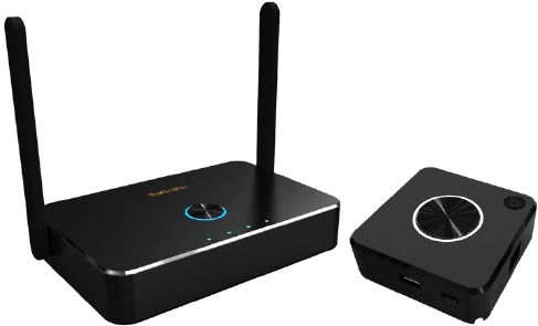
What’s in the box?
包裝內容/パッケージ内容
QuattroPod Receiver/接收器/受信機
DC IN POWER RESET
USB
HDMI OUT
ETHERNET
HDMI
Transmitter Operation 發送器操作 トランスミッタの動作
iOS
PC
QuattroPod Transmitter/發送器/トランスミッタ
5V1A
HDMI / Mini DP++
5V1A
Switch to Mobile
切換到Mobile/Mobile切り替える
Trust This Computer?
信任這台電腦?
このコンピュータを信頼しますか?
Trust
信任/信頼
Don’t Trust
否/いいえ
1. 請到設定→系統→關於手機
2. 在版本號碼輕點七下可啟用開發人員選項
安卓使用者連接前請先啟用USB偵錯
!
系統 關於手機
你現在已成為開發人員!
版本號碼 x7
Android
1. Go to Setting→System→About Phone
*Note: Please select MTP or File Transferring
in the notifications when USB is connected.
4. Plug to QuattroPod Transmitter and
Allow USB debug
Please enable USB Debugging before using.
!
5V1A
Switch to Mobile
System
About Phone
2. Click Build Number for 7 times to enable
Developer Option
You are now a developer!
x7
Build number
3. Go to Developer option→USB Debugging→ On
USB debugging
Developer options
1. 設定→システム→端末情報
USBデバッグを有効にしてから使用してください。
!
システム
端末情報
2. ビルド番号を7回クリックして、開発者向け
オプションを有効にします
これでデベロッパーになり
ました!
x7
ビルド番号
*通知:USBが接続されている場合、
通知でMTPまたはファイル転送を選択してください
4. QuattroPodトランスミッタに接続し、
USBデバッグを許可する
5V1A
Switch to Mobile
3. 開発者向けオプション→USBデバッグ→オンにする
USBデバッグ
開発者向けオプション
3. 進入開發人員選項,啟用USB偵錯
* 注意:接上手機後請選擇MTP或檔案傳輸模式
4. 將手機透過USB連接到QuattroPod
發送端並同意USB偵錯
5V1A
Switch to Mobile
USB偵錯
開發人員選項
LED Status list
Enable Host w/o source input.
ソースなしでホストを有効にする。
主持人角色但未有投影源接上。
Enable Host and casting.
ホストとキャストを有効にします。
主持人角色並投影中。
Guest standby w/o casting.
キャストなしのゲストスタンバイ。
訪客待機中無投影。
Guest requests casting and wait for allow.
ゲストはキャストを要求して許可を待ちます。
訪客要求投影並等待許可。
Enable Guest and casting.
ゲストとキャストを有効にする。
訪客投影中。
Transmitter OTA Completed.
トランスミッタOTA完了。
發送器韌體更新完成。
Enable Guest w/o source input.
ソース入力なしでゲストを有効にする。
訪客角色但未有投影源接上。
Host received request of cast.
ホストはキャストのリクエストを受け取りました。
主持人收到他方投影要求。
Host standby w/o casting.
キャストなしのホストスタンバイ。
主持人待機中無投影。
1. Under connection. 接続中。連接中。
2. Pairing/Transmitter OTA download and installation.
ペアリング,トランスミッタOTAをダウンロードして
インストールする
配對中/ 下載新韌體。
3. Fail to connection(blinking for 1minutes or more).
接続に失敗しました(1分以上点滅)
連接失敗(當閃燈超過一 分鐘)
Pairing done.
ペアリングが完了しました。
配對完成。
Transmitter OTA Fail.
トランスミッタOTAフェイル。
發送器韌體更新失敗。
?
Transmitter/發送器/トランスミッタ
Main button(Mirror button)
主按鍵(投影按鍵)
メインボタン(投影ボタン)
Single click
單按
シングルクリック
Hold for 3 seconds
長按3秒
長押し3秒
Host
主持人
ホスト
Mirror/Disconnect
投影/斷開
プロジェクション/切断する
Full screen mirror
全螢幕投影
全画面投影
Guest
訪客
訪問者
Host
主持人
ホスト
Guest
訪客
訪問者
Send mirror
request
發送投影要求
キャスト要求
を送信する
Send full screen
mirror request
發送全螢幕投影要求
全画面投影リク
エストを送信する
Side button(Control button)
側按鍵(控制按鍵)
サイドボタン(コントロールボタン)
Single click
單按
シングルクリック
Double click
雙按
ダブルクリック
Hold for 3 seconds
長按3秒
長押し3秒
Allow guest to mirror
允許訪客投影
訪問者にプロジェクトを許可する
Deny request
拒絕訪客投影
要求を拒否する
Quit all display
退出全部投影
すべての表示を終了する
3
3
Receiver/接收器/受信機
Download pairing file to USB disk
下載配對檔到USB磁碟
ペアリングファイルをUSB
ディスクにダウンロードする
Main button
主按鍵
メインボタン
Single click
單按
シングルクリック
QuattroPod
Quick Start Guide
Rev. 1.055
Introduction
Firstly, thanks for choosing QuattroPod as wireless presentation facility. It
integrates powerful dual core SoC and advanced 802.11ac 5G Wi-Fi to provide you
a smooth wireless display experience, and it supports almost all devices. Our
features not only support ‘’Split Screens Display”, “ Host Control System” but also
let cross platform devices throw the contents in APP-independence. It provides a
more friendly and efficient environment for BYOD (Bring Your Own Devices) with
wireless projection in legacy/ existing projectors or monitors you have! Enjoy them
and help you to achieve more collaboration!
What’s in the box?
When you open the box, it contains
QuattroPod Receiver (hereinafter called Rx) with external antennas, x1
QuattroPod Transmitter (hereinafter called Tx) with USB cable, x2
5V Universal Adapter, x1
HDMI Cable for Rx, L 100cm, x1
HDMI Cable for Tx, L 30cm, x1
DP Cable for Tx, L 30cm, x1
Quick Start Guide, x1
System Requirement:
-PC: Any PC or laptops with HDMI output or mini DP (DP2.0) output
-Tablet/Smart Phone: iOS 10 above and Android 5.0 above
*Important: Android device must turn ADB mode in advance
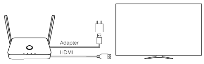
Installation:
QuattroPod RX:
1. Connect Power with the adaptor
2. Connect HDMI with HDMI port with the projectors or displays.
*Notice: Rx is compatible with VESA mounting screw holes. Please use the 5x5 bracket
and M4 screws.
QuattroPod TX:
1. There are 2 ways to supply power to TX.
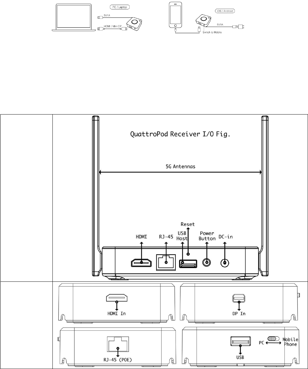
-Through USB 5V(required 1A at least, through adaptors or USB ports of laptops)
or
-Through POE (Power over Ethernet): Ethernet switch or router needs to support
standard POE (Power over Ethernet) function and keep it active.
2. To connect TX with Laptops, to connect HDMI or DP2 ports with proper cables.
To connect TX with Smart phones, to connect USB port with proper cable with
phone’s connectors such as micro USB, Lighting or USB type C.
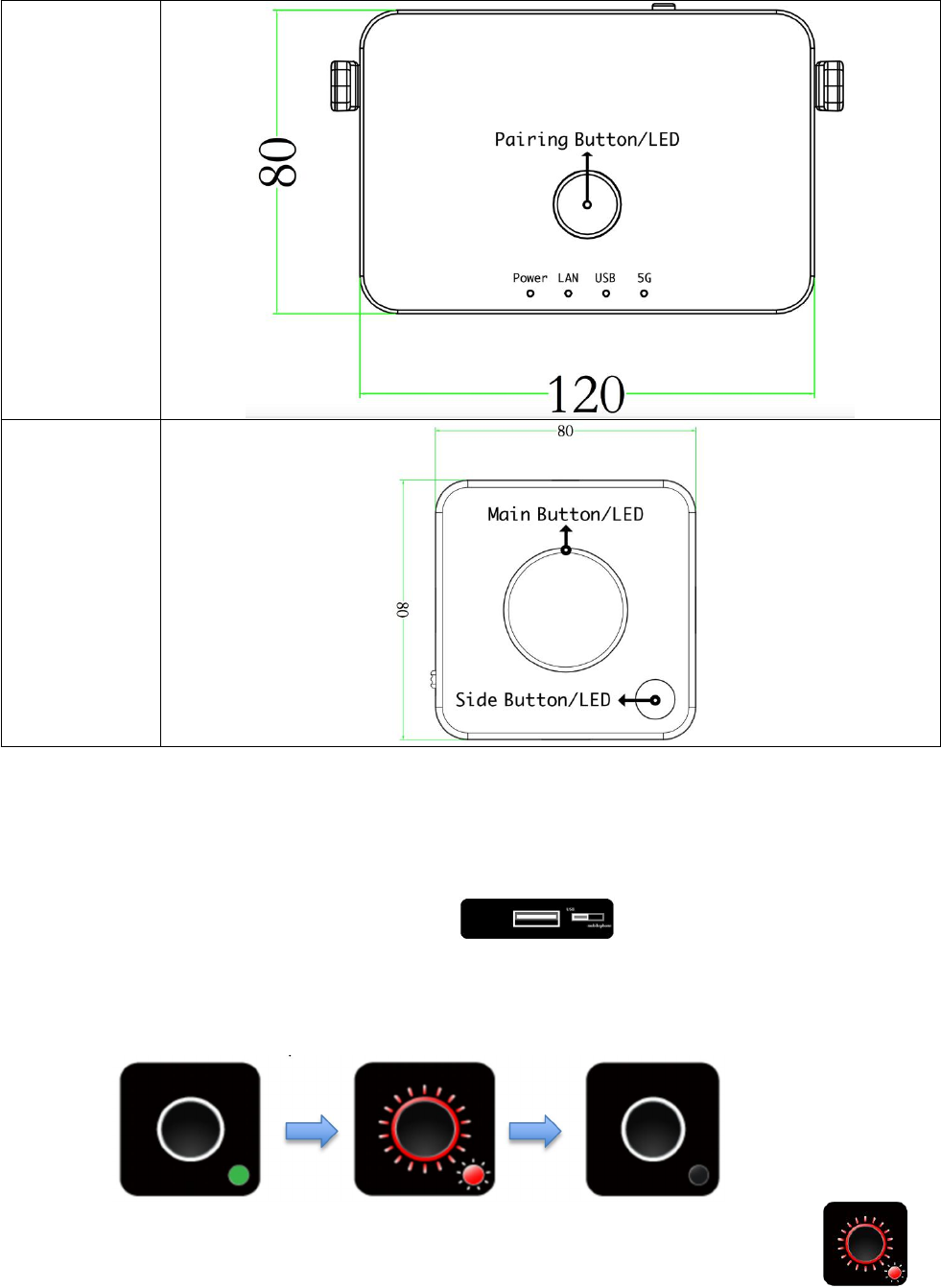
I/O Descriptions:
QuattroPod
Receiver
QuattroPod
Transmitter
LED Indication:
QuattroPod
Receiver
QuattroPod
Transmitter
Pairing:
To pair Quattro TX with RX for first time use may be needed. It’s suggested if you are not sure
QuattroPod TX has ever paired with the Quattro RX you want to cast.
1. Adjust the switch of the side to right .
Plug Quattro TX’s USB cable onto Quattro RX’s USB port in the rear.
2. The Main LED and Side LED will start blinking while pairing, after pairing is done, the Rx’s
main LED will turn to White and Tx LED will stop blinking.
3. LED indicator’s sequence will be
Notice: when you see main button & side button remain blinking for while , it
has 3 possibilities, Upgrading, Pairing, or Error (Disconnecting).
Finger Tips
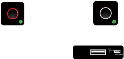
Before understanding the status of our Quattro, let us introduce the definition of the LED Lights.
There are 2 LED indicators on Quattro RX upside surface. One is in central named Main Button. The
smaller button named Side Button.
Main Button indicated the projection status. There are 4 models and meanings are-
No Light - no Source for projecting
White Light on - in projecting
Red Light on - no projecting
Red Light Blink - ask for projecting or yet connecting to Quattro RX(*)
Side Button indicated the role status, Host or Guest. There are 3 models and meanings are-
Green Light on - role of Host
Red Light on - role of Guest
Red Light Blink - yet connecting to Quattro RX(*)
* If both Main Button & Side Button are blinking in red simultaneously, which means waiting for connecting to
Quattro TX. If it lasts too long, please remove power plug and re-plug again.
1. Make sure Quattro RX has been turned on and Quattro TX has been paired and well
powered.
2. Connect device either Laptop or mobile phones** with powered Quattro TX. The device
that is regarded as “Host” should complete connecting to Quattro TX to Quattro RX. The
Quattro TX light will be turn to and click once, turn to and Host’s
content will show on screen.
** When connect to smart phones, make sure the USB side switch adjust to left.
TX OTA (Over The Air) Functions-
The TX’s Firmware can be updated through connecting to Internet. We provide several ways to
activate the OTA procedure,

LED Status list
Activate Host
without source
input
Activate Guest
without source input
Activate Host & in
projecting
Host received request
of projection
Guest standby
without projecting
Host standby without
projecting
Guest send request
of projection and
wait for allow
1. Under connection
2. Pairing/TX OTA
3. Fail to connection
(blinking over
1minutes)
Activate Guest & in
projecting Pairing done
TX OTA Complete TX OTA Fail
When Quattro RX is successfully turned on, below screen will be shown on display-
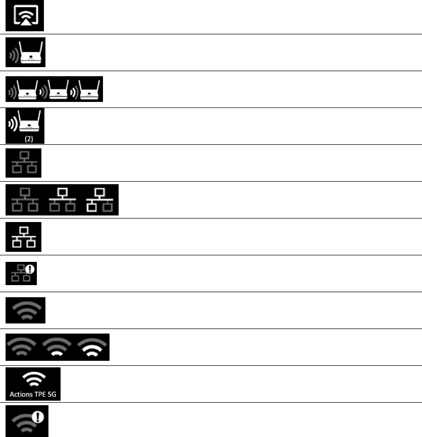
Function & Link Status-
* Outbound link can select only one of Wi-Fi and RJ45 wire line (LAN).
Airplay activated after web setting. (Default is off)
Quattro RX has been powered on, however, there is
neither Quattro TX nor device linked.
Shift in 3, which means “under pairing” or “building the
connection”.
Complete pairing or connection, the number showed total
Quattro TX or Device linked.
RJ45 wire line disconnected.
Shift in 3, which means “building the connection”.
RJ45 wire line connected and IP acquired
IP conflict or other network error.
Outbound Wi-Fi disconnected.
Shift in 3, outbound Wi-Fi is connecting.
Outbound Wi-Fi connected with the router name shown
underline.
Wi-Fi connection Fail, Invalid password or other Errors
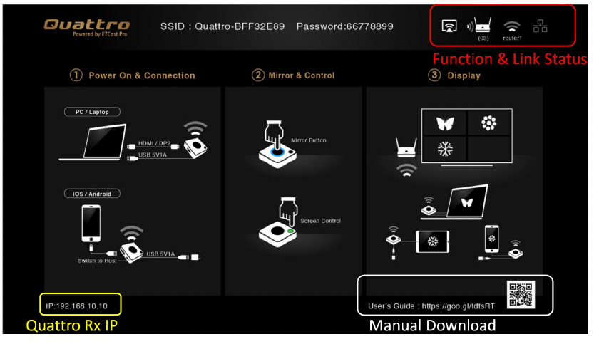
Web Setting
Quattro RX IP- when Devices (either laptops or mobile phones) connect with Quattro RX with SSID
& Password directly, applying the IP in web browser can enter Admin setting page for more
advance setting.
1. Preparation-
To access the setting page, you have to choose either way to connect the devices.
1.1 Direct link- you can apply notebook or mobile phone to search Quattro RX by wifi and key in
relative SSID and Password. Turn on web browser and enter “192.168.168.1” in the address
bar.
1.2 Through Wifi AP or Routers- if your Quattro RX has been connected to a certain networking
device, you can apply notebook or mobile phone to connect the same device. Turn on web
browser and enter the address show in mainpage in the Quattro Rx IP shown below.
Once done, the page will show as below-
- to indicate menu icon.
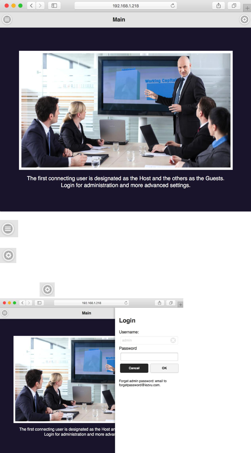
- to indicate log-in icon.
2. Log in-
Press the on the right up corner to log in.
3. Start to set up
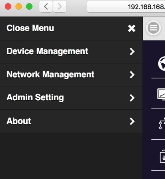
3.1 Click the menu button on the left up corner and there are drawer show 3 setting functions.
They are Device Management,Network Management, and Admin Setting, and About
which indicates device version, IP addresses and wifi frequency..etc.
4. Device Management-
This section helps to manage user interface language, output resolutions, Max connection and
QuattroPod Receiver & Transmitter pairing file download.
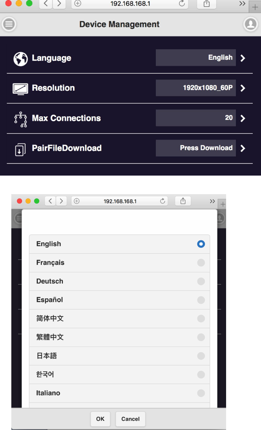
4.1 Language- click it and choose the language you prefer to show in the webpage.
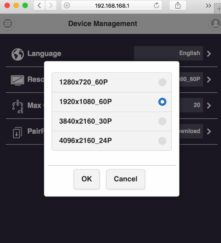
4.2 Resolution-
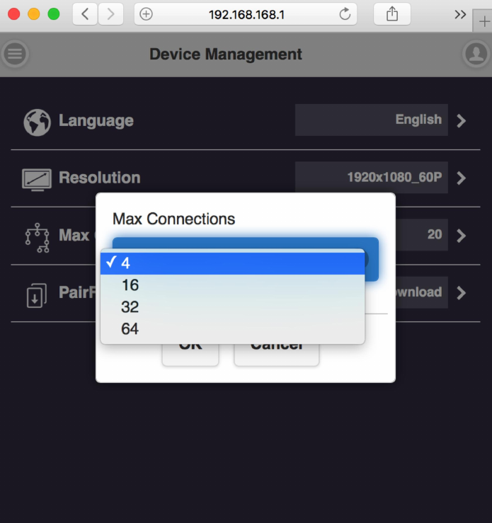
4.3 Max Connection- to set the maximum users of the Receiver. Default is 20 users.
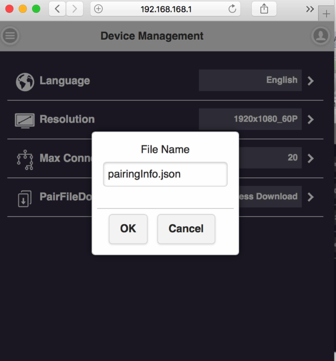
4.4 Pair File Download- down load the pairing file from here and copy to USB drive. Plug in
Transmitter for pairing* when the Receiver has been installed on the ceiling or wherever
difficult to plug directly.
The switch of USB on Transmitter shall be adjusted to “mobile”.
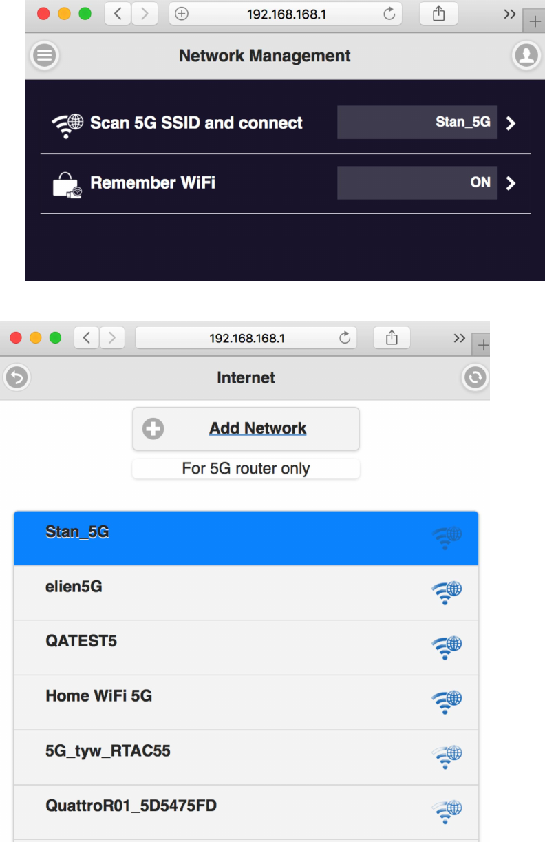
5. Network Management- mainly provide outbound Wi-Fi setting.
5.1 Scan 5G SSID and Connect- this function can help you to scan available Wi-Fi AP and join.
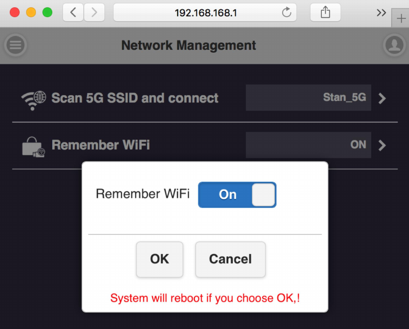
5.2 Remember Wi-Fi- it to provide options to remember the AP setting parameter or
not.
6. Admin Setting-
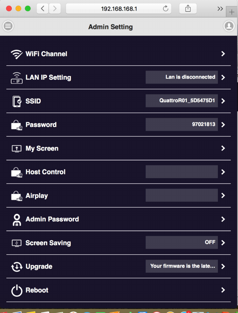
6.1 Wi-Fi Channel- to select the channel between QuattroPod Receiver & Transmitter to adjust
the performance.
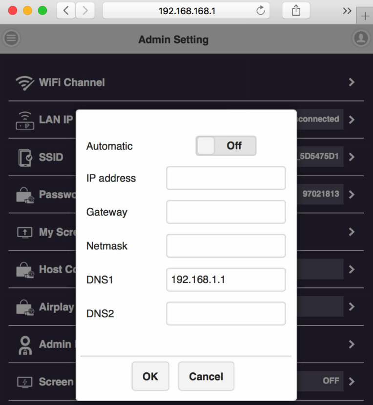
6.2 LAN IP Setting- to configure the wire line connection through LAN cable. *we can support
only one connection, either LAN or Wi-Fi at one time.
6.3 SSID- to set the SSID indication of the Receiver on the main screen.
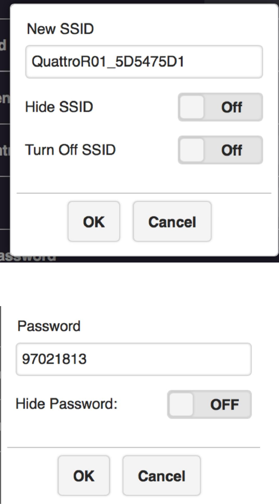
6.4 users can change password of the Receiver, or hide the password to avoid connections
without authorization.
6.5 My Screen- Users can replace the theme of the main page of Receiver by uploading graphic
or photos.
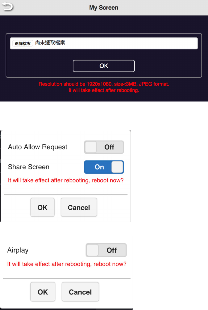
6.6 Host Control- it can be selected the mode of cast request. Auto Allow means the new
request will be cast on screen directly. Share screen will present in screen split when it was on.
If set it off, the new casting will be full screen mode.
6.7 Airplay- to turn on/off the iOS /Mac devices can cast without QuattroPod Transmitters.
6.8 Change Admin Password- to change the web setting’s log in password.
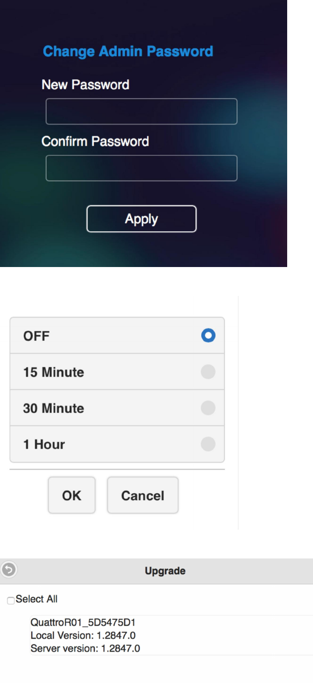
6.9 Screen Saving- to configure the screen off when the input is idle for certain time.
6.10 upgrade firmware- to remind users if there is new firmware released and execute the
upgrade (* but the Receiver must connect to internet)
6.11 Reboot- to reboot the equipment.
7. About- showing the information of the Receiver.
.
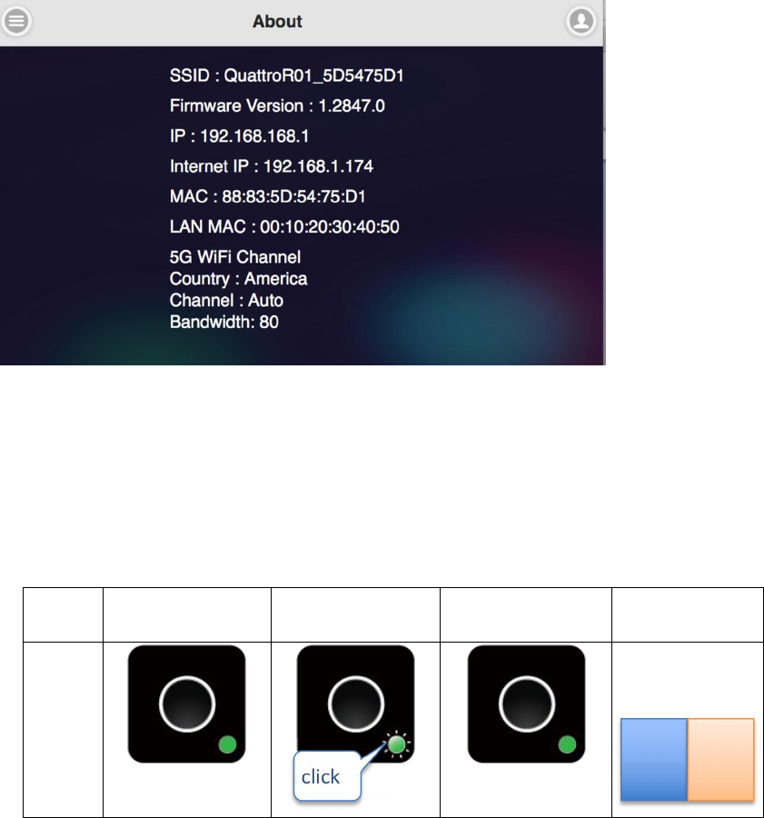
Frequent Applications & Operation
1. Host has projected on screen, and quest required sharing the screen. Host allows.
Indicator 1
Indicator 2
Indicator 3
Result of
screen
Host
Host
Guest
Guest
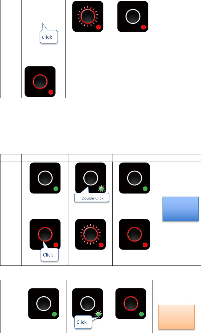
2. Host has projected on screen, Host rejects Guest’s screen share request.
Indicator 1 Indicator 2 Indicator 3 Result of screen
Host
Host
Guest
3. From share screen mode, Host allows Guest full screen request.
Indicator 1 Indicator 2 Indicator 3 Result of screen
Host
GUEST
This product can only be used indoors, antenna type only allows use of PCB antenna
Guest
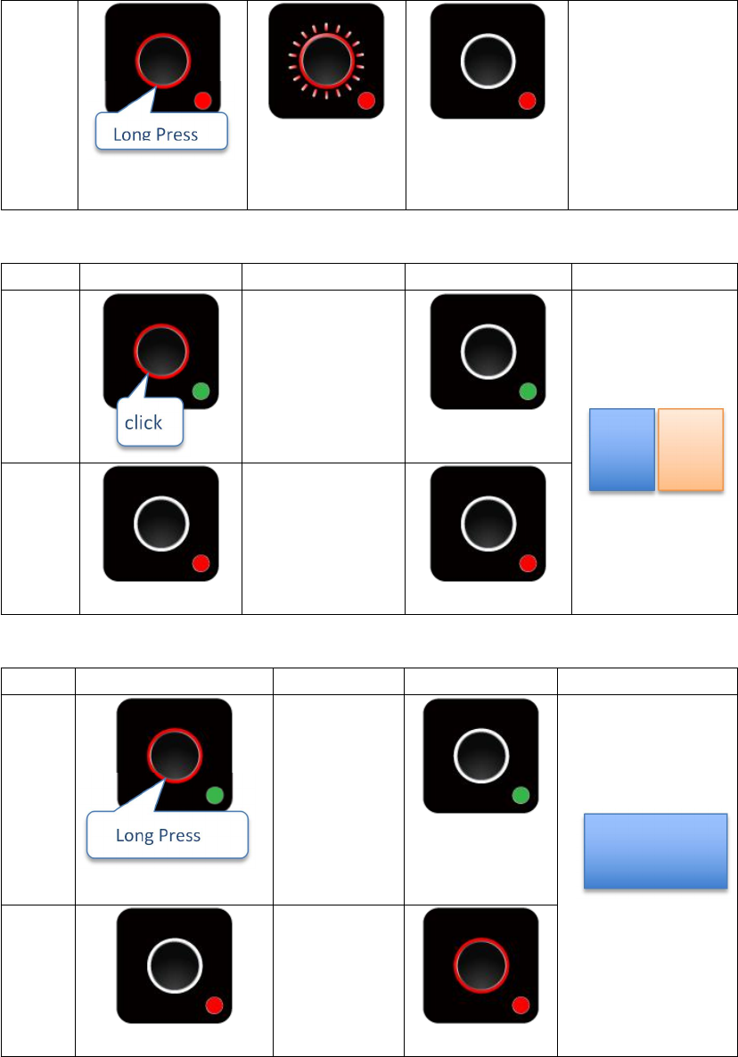
4. Guest full screen mode, Host retrieves share screen request.
Indicator 1 Indicator 2 Indicator 3 Result of screen
Host
Host Guest
Guest
5. Guest full/share screen mode, Host retrieves full screen request.
Indicator 1 Indicator 2 Indicator 3 Result of screen
Host
Host
Guest
©2017 Actions Microelectronics Co., Ltd. All right reserved. Quattro Pod or Quattro are trademarks of
Actions Microelectronic Co., Ltd., registered in China and other countries. Other product and company
names mentioned herein may be trademarks other respective companies.
and PIFA Antenna
The transmitter can be used as a receiver and the receiver can be used as a transmitter
FCC STATEMENT
1. This device complies with Part 15 of the FCC Rules. Operation is subject to the
following two conditions:
(1) This device may not cause harmful interference.
(2) This device must accept any interference received, including interference that may
cause undesired operation.
2. Changes or modifications not expressly approved by the party responsible for
compliance could void the user's authority to operate the equipment.
NOTE: This equipment has been tested and found to comply with the limits for a Class
B digital device, pursuant to Part 15 of the FCC Rules. These limits are designed to
provide reasonable protection against harmful interference in a residential installation.
This equipment generates uses and can radiate radio frequency energy and, if not
installed and used in accordance with the instructions, may cause harmful interference
to radio communications. However, there is no guarantee that interference will not
occur in a particular installation. If this equipment does cause harmful interference to
radio or television reception, which can be determined by turning the equipment off
and on, the user is encouraged to try to correct the interference by one or more of the
following measures:
Reorient or relocate the receiving antenna.
Increase the separation between the equipment and receiver.
Connect the equipment into an outlet on a circuit different from that to which the
receiver is connected.
Consult the dealer or an experienced radio/TV technician for help.
FCC Radiation Exposure Statement
This equipment complies with FCC radiation exposure limits set forth for an
uncontrolled environment. This equipment should be installed and operated with
minimum distance 20cm between the radiator & your body