Winnix Technologies HYM730 UHF RFID Reader Module User Manual
Winnix Technologies Co., Limited UHF RFID Reader Module
User Manual
UHF RFID Reader/Reader Module
DEMO Software User Manual
V1.1
Winnix Technologies Co., Limited

www.winnix.net
2
Content
Content………………………………………………………….…………………………………………….………2
1. Introduce………………………………………………….…………………………………………….………3
2. User Guide……………………………………………………………………………….……………….……3
2.1 Language……………………………………………………………………………….……….……3
2.2 Connection………………………………………………………………………..…………….……4
2.1.1 Ethernet connection……………………………..…………………………………….…4
2.1.2 RS232 connection……………………….……………………………………………….…4
2.3 Single inventory operation……………………………….……………………..………….…5
2.4 Multiple inventory operation…………………………….……………….…………….……6
2.5 RF output power setting…………………………………….…………………………….……7
2.6 Region setting………………………………………………….……………………………….……7
2.7 Frequency hopping setting…………………………………………………….………...……8
2.8 Version info……………………………………………………………………………………...……8
2.9 Temperature info…………………………………………………………………………..…...…9
2.10 Recommended Link setting……………………………………………………………...……9
2.11 Antenna setting………………………………………………………………………………...…..9
2.12 Multiple inventory Delay time setting………………………………………………..…..9
2.13 Antenna working and interval time setting……………………...…………….…….10
2.14 Buzzer setting..………………………………………………………………………………….….10
2.15 GPIO setting…….…………………………………………………………………………………...11
2.16 CW setting …………………………………………………………………………………………….11
2.17 RX ADC info……………………………………………………………………………………………11
2.18 Algorithm setting……………………………………………………………………………………11
2.19 Single inventory timeout setting…………………………………………………………….12
2.20 Select and Query Setting………………………………………………………………………..12
2.21 Tag reading/writing setting…………………………………………………………………….12
2.22 Tag Lock setting………………………………………………………………………………………13
2.23 Tag Kill setting…………………………………………………………………………………………14
2.24 FastID function………………………………………………………………………………………..14
2.25 TagFocus function……………………………………………………………………………………15
www.winnix.net
3
1. Introduce
The Demo software user manual is used for HYM730/HYM740/HYM750 serial modules and
HYR810/HYR820/HYR830 series readers;
Support Chinese and English language;
Support RJ45 connecting. Adopt TCP long connection method, slave computer as TCP server,
host computer demo software as the TCP client side. (Notice: RJ45 connecting only for
HYR830 reader)
Support RS232 connecting, baud rate 115200, 1 bit for start, 1 bit for stop, 8 bits for data.
2. User Guide
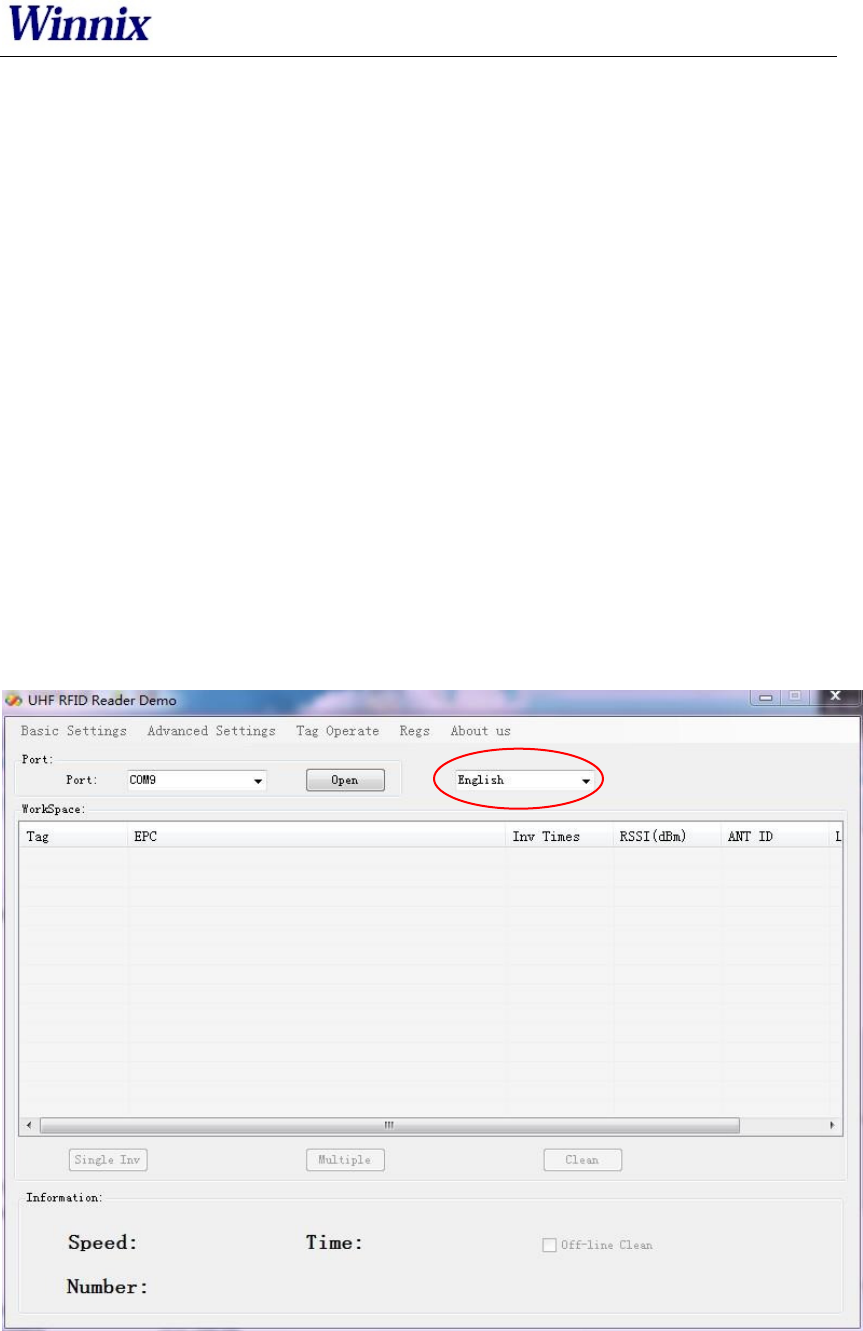
2.1 Language
Two optional languages are supported:
Simply Chinese
English
Open the DEMO software, as picture 1, click red marked area, could choose language.
Picture 1 Opening interface
www.winnix.net
4
2.2 Connection
Demo software support two optional connecting, Ethernet and RS232 serial connections.
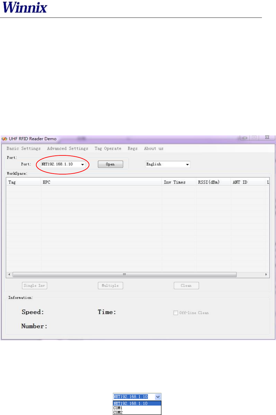
2.2.1 Ethernet connection setting
Default IP address of the reader is 192.168.1.10. If connecting in Ethernet (RJ45), please set
IP address of PC at same range, such as 192.168.1.100. Before connecting, make sure IP
address of PC could be passed at Ping operation.
Connections are displayed with different prefix. If connecting with RJ45, type NET+IP at
the drop-down box of port.
For example, connect to 192.168.1.10, type NET192.168.1.10 as below picture.
Picture 2 Ethernet port connection
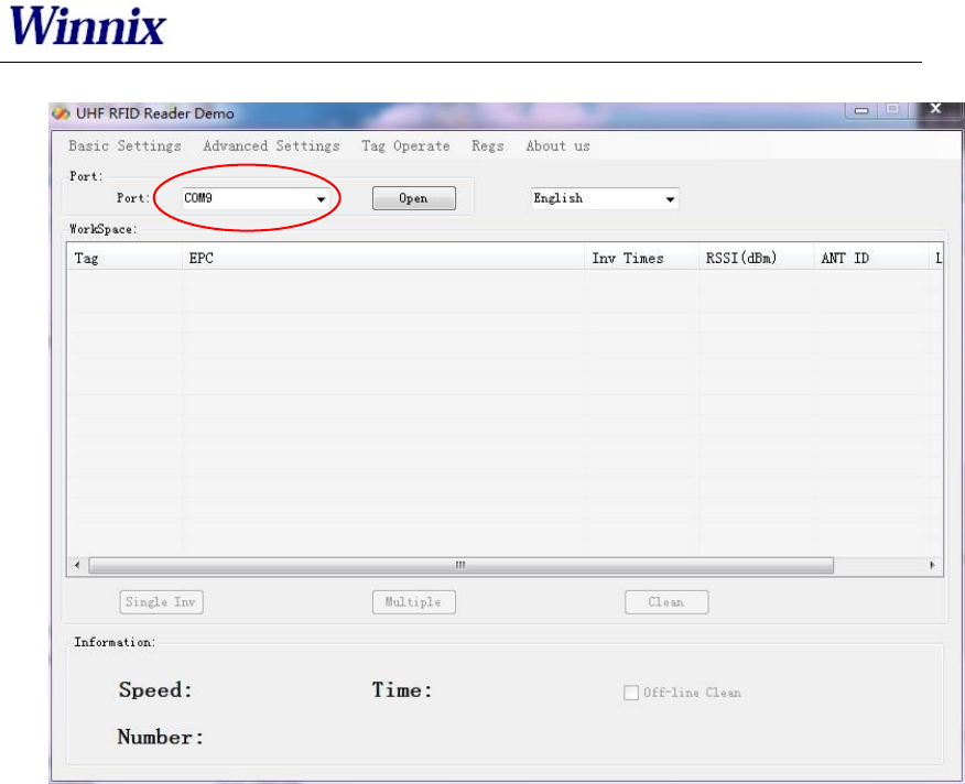
2.2.2 RS232 connection
Demo software could automatically display usable COM ports, click drop-down box, you will
see below.
Picture 3 Automatic identify serial port
RS232 connection is with a prefix of COM, which user dont need to input. What users have
www.winnix.net
5
to do is to choose correct COM number, and then it should be connected, as below picture.
Picture 4 RS232 port connection
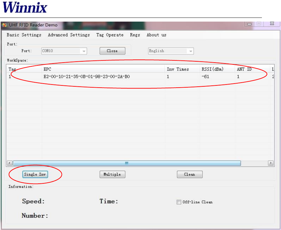
2.3 Single inventory operation
Single inventory operation is in singe ask and single answer method of reading. Each
inventory will result an acknowledgement frame. In each single inventory, only one tags EPC
data could be gotten.
Single inventory mode supports to inventory tag function at any length EPC code. At
workspace area, it could display EPC code, Inventory times, RSSI for each tag, as below
picture.
www.winnix.net
6
Picture 5 Single inventory mode
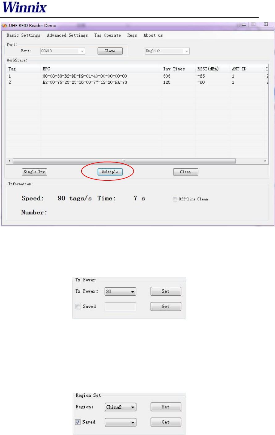
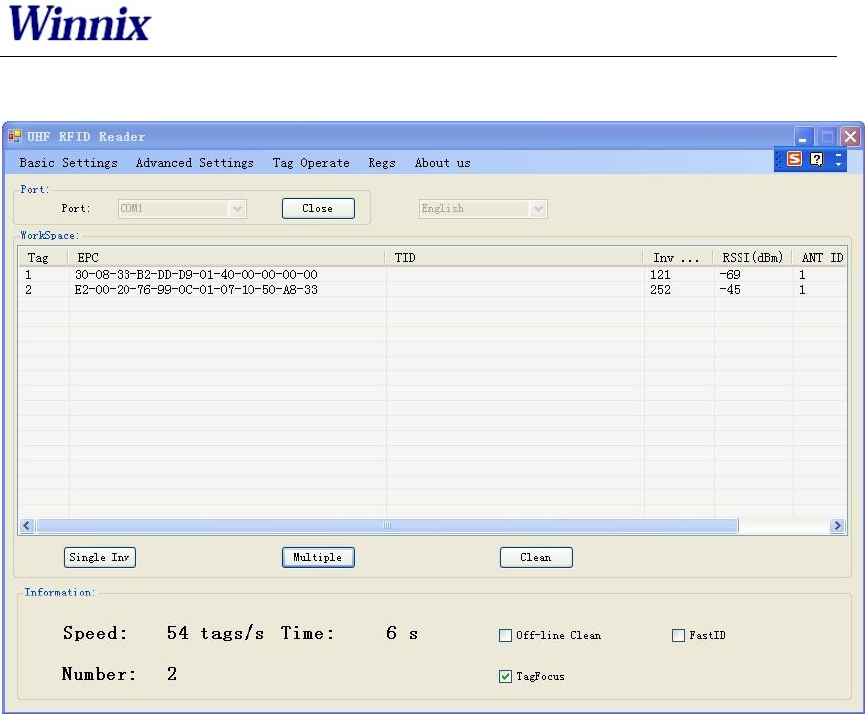
2.4 Multiple inventory operation
Below picture is for multiple inventory mode. Inventory times are non-limited. At
information area, it will display Inventory speed, time and tag numbers. Click off-line clean,
it will launch the function. If a tag is not read in 4 seconds, the marked color of the tag will
turn grey, if over 8 seconds, the tag will be cleared from workspace.
www.winnix.net
7
Picture 6 Multiple inventory mode
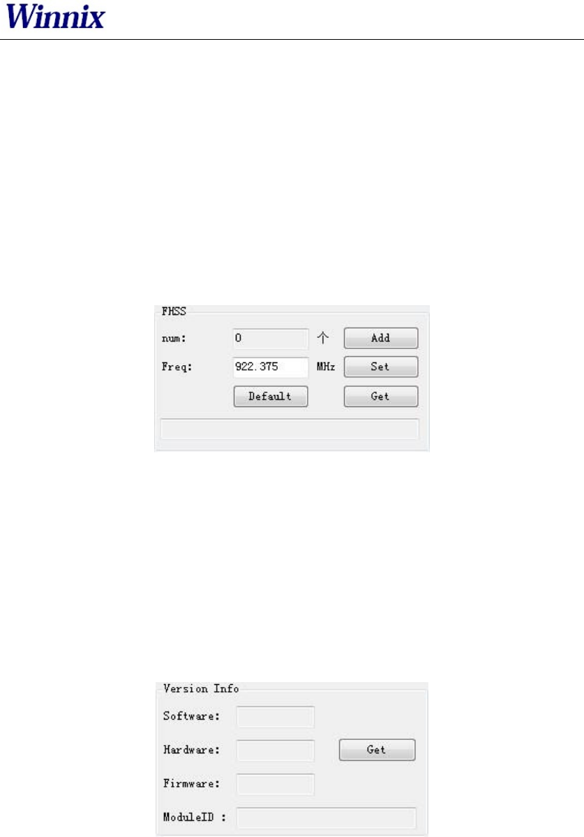
2.5 RF output power setting
TX power setting is in basic settings section, below picture is for TX power setting.
Picture 7 RF output power setting
The TX power range is 5-30dBm, with 1dBm stepping up. Set the picked power, and
then get for checking the result.
Choose "save", the setting will be kept after power off.
2.6 Region setting
Region setting is in basic settings section, as below picture.
Picture 8 Region setting
www.winnix.net
8
Region setting includes
China1 area (840.625MHz~844.375MHz),
China2 area (920.625MHz~924.375MHz),
Europe area (865.7MHz~867.5 MHz),
USA area (902MHz~928MHz),
Korea and Japan area.
Choose the frequency band at your area, and then click set, get is to check the
current band you have chosen.
Choose "save", the setting will be kept after power off.
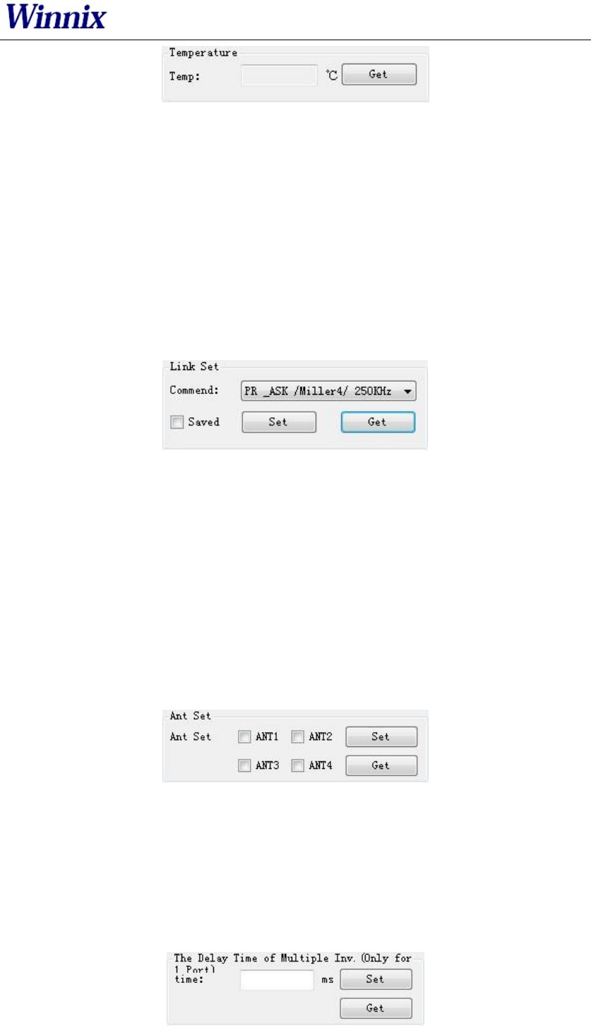
2.7 Frequency hopping setting
Frequency hopping setting is in basic settings as below picture.
Picture 9 Frequency hopping setting
Click get, you will see the each hopping points of the frequencies.
Fixed frequency setting: fill in the frequency at the blank then click add, then click
set, if successful, it will notice. Click get can check out the set value.
Self-defining frequency hopping setting: input one frequency point, click add; then
input another, click add. Repeat till you add all frequency points, then click set. You
can click get to check if setting successfully.
2.8 Version info
Version information is displayed in basic settings as below picture.
Picture 10 Version information
Click get, you will get the version information, including Software version, Hardware
version, Firmware version and Module ID.
2.9 Temperature info
Temperature info is displayed in basic settings as below picture.
www.winnix.net
9
Picture 11 Temperature information
Click get to see the working temperature information. For normally, the temperature
range is between -40 – 85 degree Celsius.
When the “temperature protect” is activated (the default is turn on), once the temperat
ure is over 65℃, the rate of inventory would fell by 50%; If the temperature is over
85℃, the reader-module would stop working automatically, and it would back to work
again only the temperature below 85℃.
More than 80℃ on the life of the module will have a certain impact.
2.10 Recommended link setting
Link setting is in basic settings as below picture.
Picture 12 Recommended link setting
Recommended Link Settings:
DSB_ASK /FM0/40KHz
PR_ASK/Miller 4/250KHz
PR_ASK/Miller 4/300KHz
DSB_ASK /FM0/400KHz
Default Link setting is PR_ASK/Miller 4/250KHz.
Choose save, the setting will be kept after power off.
2.11 Antenna setting
Antenna setting is in Basic Setting as below picture.
Picture 13 Antenna setting
ANT2, ANT3, ANT4 are not applied for single port module. For four channels module
and reader, you could choose one or more antennas to work, and also can set the
working time for each antenna.
2.12 Multiple inventory Delay time setting
Multiple inventory delay time setting is in Basic Setting, as below picture.
www.winnix.net
10
Picture 14 Multiple inventory Delay time setting
The setting is for module waiting time after one inventory cycle during the multiple
inventory working. This is only applied for single port module. Default value is 0
during multiple inventory. At such case, the module will be working at full load, while
the module temperature will be higher.
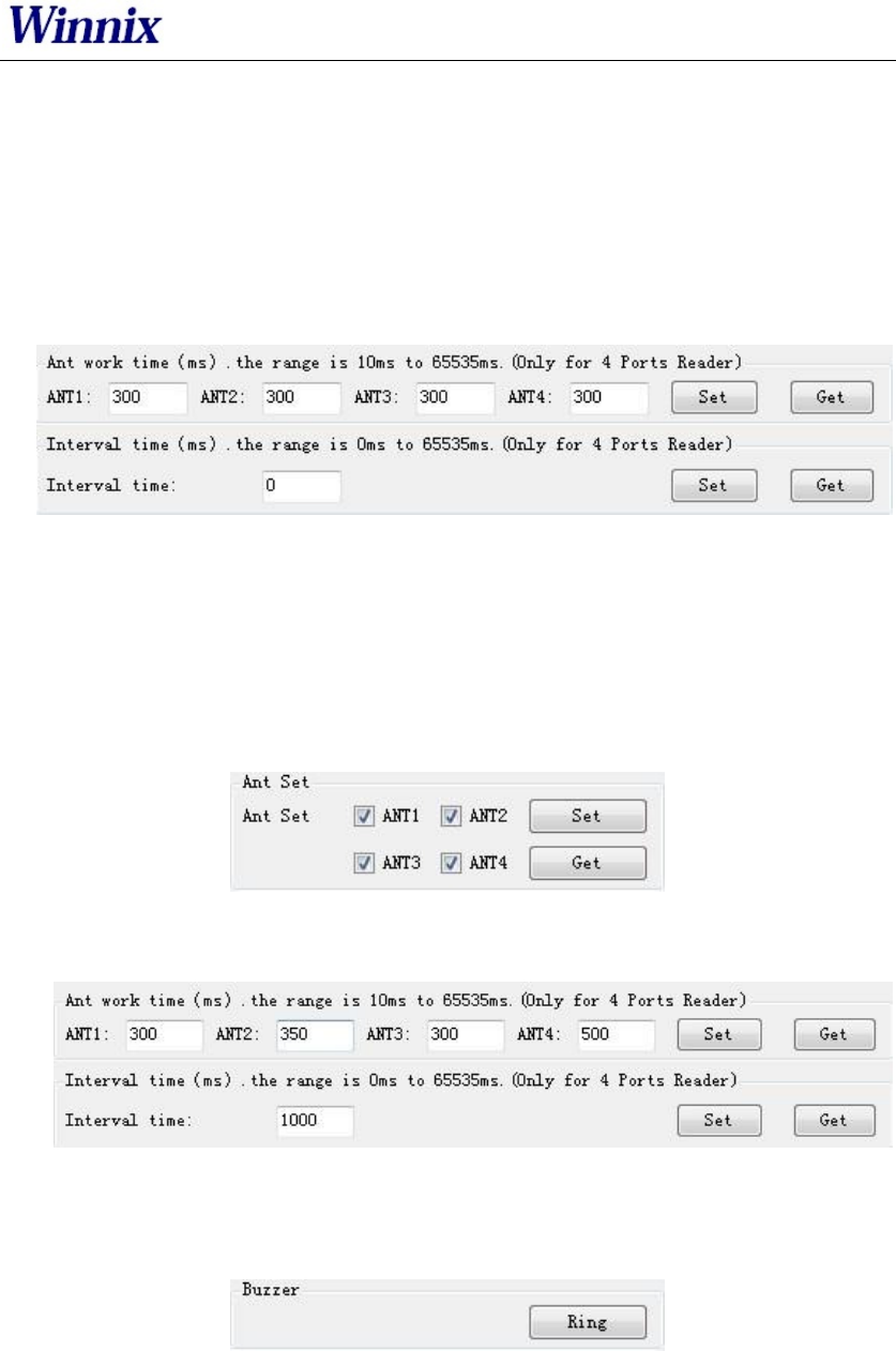
2.13 Antenna working and interval time setting
Antenna working and interval time setting is in Basic Setting, as below picture.
Picture 15 Antenna working and interval time setting
The setting is for each antenna working time and interval time during multiple
inventory. Before the setting, you should choose the antenna number.
For instance, if want to set ANT1 of working time 300ms, ANT2 of working time
350ms, ANT3 of working time 300ms, ANT4 of working time 500ms, and waiting
1000ms for once reading cycle, see following steps:
a) Click ANT1, ANT2, ANT3, ANT4, and set;
b) Set ANT1 of working time 300ms, ANT2 of working time 350ms, ANT3 of working
time 300ms, ANT4 of working time 500ms, and interval time is 1000ms.
2.14 Buzzer setting
Buzzer setting is in Basic Setting as below picture.
Picture 16 Buzzer setting
Notice: The function is only for HYR830 reader.
Click Ring, you will hear the alarm from the reader.
www.winnix.net
11
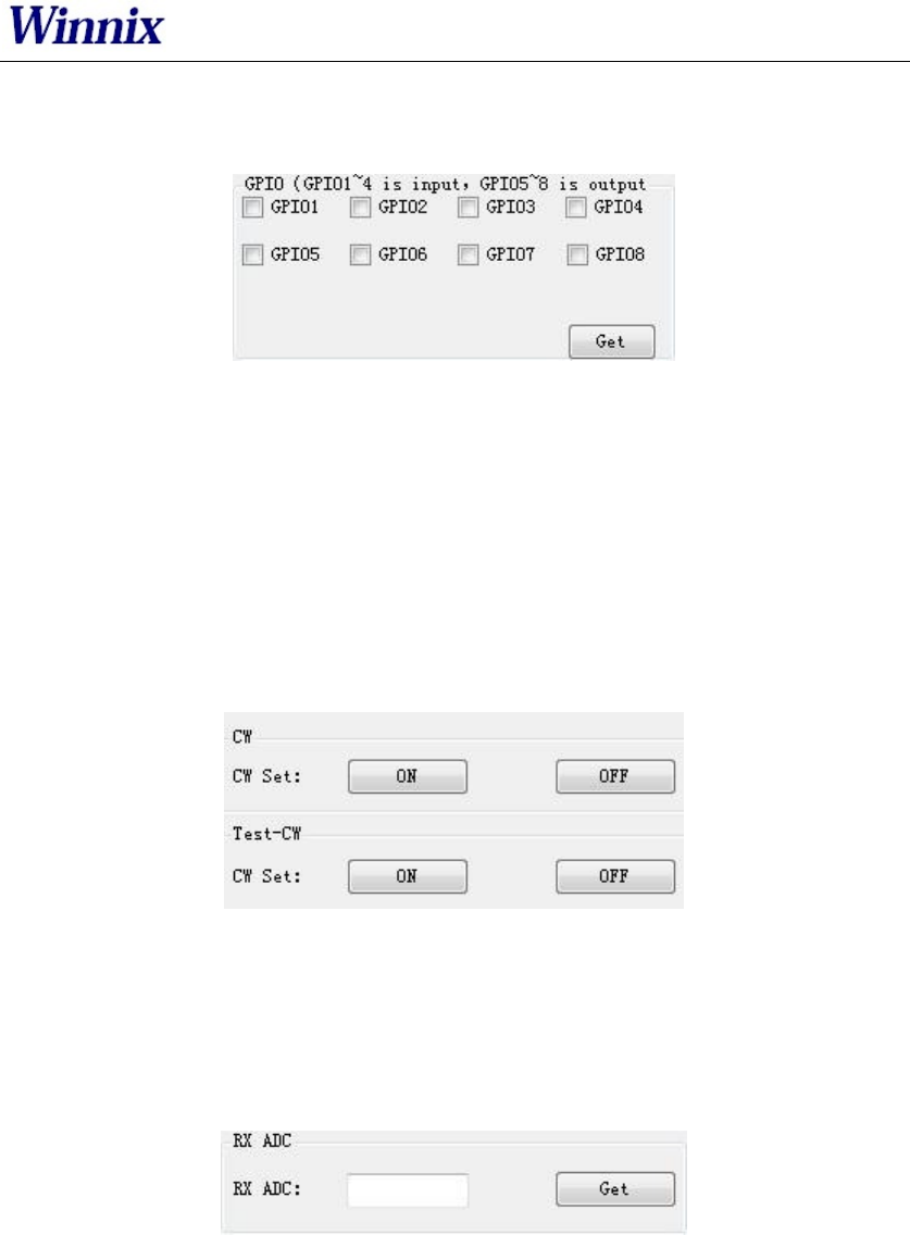
2.15 GPIO setting
GPIO setting is in Basic Setting as below picture.
Picture 17 GPIO setting
Notice: HYM series modules only have 3 output IO ports (GPIO1, GPIO2 and GPIO3).
HYM830 reader has 4 output IO ports (GPIO1, GPIO2, GPIO3, GPIO4), and 4 input IO
ports (GPIO5, GPIO6, GPIO7, GPIO8)
The picked output IO ports will output high level, otherwise will output low level. If
connecting input IO ports at high level, click get, you will see the picked IO ports;
while at low level, the IO ports are not picked.
2.16 CW setting
CW setting is in advanced settings as below picture.
Picture 18 CW setting
Click ON to open single carrier wave transmit, OFF is to close single carrier wave
transmit. Test-CW is for testing, please ignore it.
2.17 RX ADC info
RX ADC information is displayed in advanced settings as below picture.
Picture 19 RX ADC information
RX ADC is very important for checking the matching and connection of the antenna
with module or reader. If the data is above 10, there may be connection problem or
no-matching. At the time, please re-check the connection of antenna, or remove it, otherwise it
will damage the module or reader. If the data is below 10, the antenna can be worked.
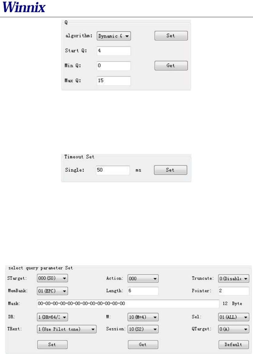
2.18 Q setting
In Advanced Settings, below is the picture of Q setting.
www.winnix.net
12
Picture 20 Q setting
There are two ways of dynamic Q and static Q. Dynamic Q is recommended, as it
could automatically adjust the Q value to achieve most fast inventory.
2.19 Single inventory timeout setting
In Advanced Settings section, below is the picture for single inventory timeout setting
Picture 21 Single inventory timeout setting
This function is only for single inventory. If single read is unsuccessful, after the
overtime, the reader will report the result. If the reading is successful during the
overtime, the response will be appeared immediately.
2.20 Select and Query Setting
In Advanced Settings section, below is the picture for Select and Query parameter
setting
Picture 22 Select and Query setting
Please read detail instruction for Select and Query command in ISO18000-6C
protocol.
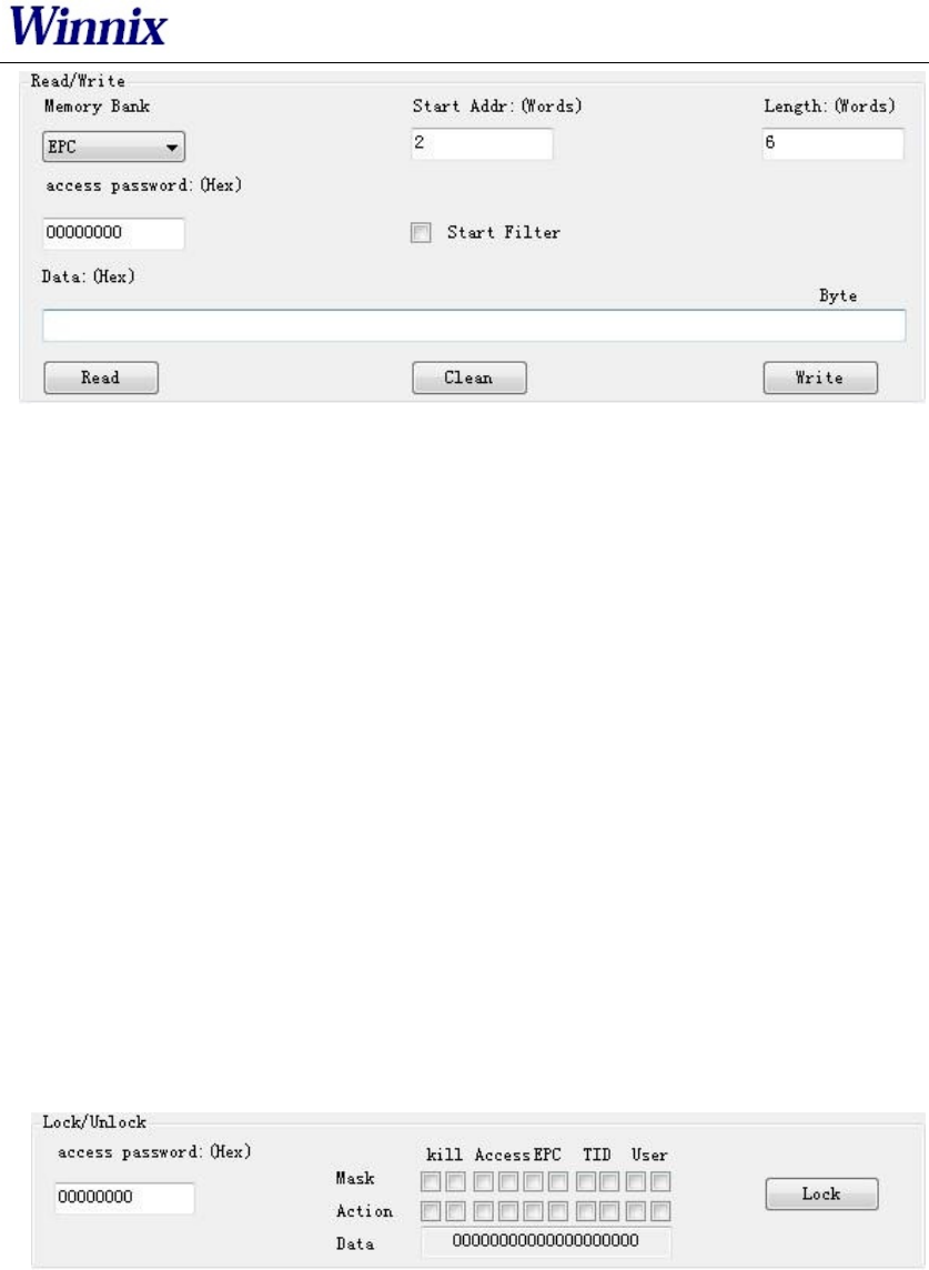
2.21 Tag reading and writing setting
In Tag Operate section, below is the picture for tag reading/writing setting
www.winnix.net
13
Picture 23 Tag reading and writing setting
Memory Bank is data area of the tag, which includes RFU, EPC, TID and USR.RFU is for
password zone of the tag, including Access Password (AccPwd) and Kill Password
(Killpwd). EPC is the ID number of the tag, usually at 12 bytes. TID is the worldwide
sole ID code, and includes the information of tag IC company. USR is data zone for
users, for some kind of tag there is no the USR data zone.
Start address is for the beginning address of data reading and writing. Unit is word
(One work equals to 2 bytes).
Length is to show the length of data write. Unit is word (One work equals to 2 bytes).
Access password: this is only for the reading and writing on those locked tag. Notice
that you can read EPC information of the tag even the tag has been locked, but have
to access the password for writing. TID is only for read, cant for write.
Read/Write setting is usually operated with filter operation, which means you can
read/write those picked EPC tag, and avoid to reading/writing un-picked tags. Steps
are as following:
Find the tag on workspace which you want to reading and writing, double-click the
EPC number, enter tag operate interface, then you can operate.
2.22 Tag Lock setting
In Tag Operate section, below is the picture for Tag Lock setting.
Picture 24 Tag lock setting
At RFU zone, KillPwd and AccPwd could set separately.
There are four kinds of operation for lock setting in each zone, including Unlock,
Normal lock, Permanent lock, Permanent Unlock, and usually for Lock and normal
lock operations.
Tag lock setting is usually operated with filter operation, which means you can lock
those picked EPC tags, and avoid locking un-picked tags. Steps are as following:
Find the tag on Workspace which you want to lock, double-click the EPC number,
enter tag operate interface, then you can operate.
www.winnix.net
14
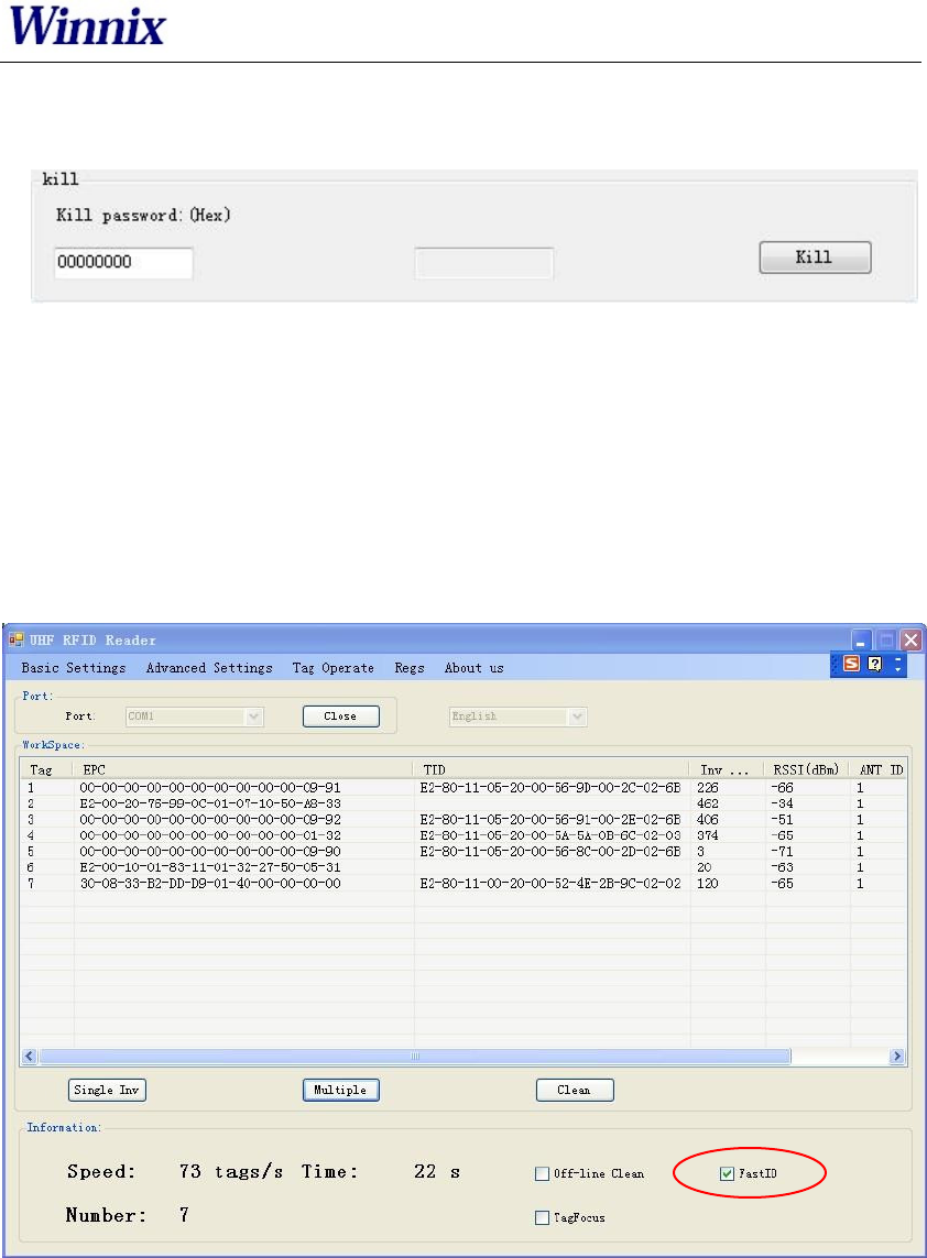
2.23 Tag Kill setting
In Tag Operate section, below is the picture for Tag Kill setting.
Picture 25 Tag kill setting
It is supported by ISO18000-6C protocol the reader could kill the tags permanently. Please
caution the killed tag could not be usable.
Tag Kill setting is usually operated with filter operation, which means you can kill the picked EPC
tags, and avoid killing un-picked tags. Steps are as following:
Find the tag on Workspace which you want to kill, double-click the EPC number, enter tag
operate interface, then you can operate.
2.24 FastID Function
Picture26 FastID Operation screen
ClickFastIDthen you can start FastID function
When you open FastID, on single inventory and continuous inventory, the EPC and TID of
the tag will be shown together.
Attention, only if the tag support FastID function, then you can use this function, if the tag
didnt support this function, you only can get EPC.
www.winnix.net
15
2.25 TagFocus Function
Picture27 TagFocus Operation screen
ClickTagFocus,then you can start TagFocus function
OEMsinformation:RealIDTechnologyCo.,Ltd.wasestablishedinDecember2012,theregistered
capitalof990millionyuan.ItisaprofessionalcompanyspecializinginRFIDsystemdesign,
equipmentdevelopmentandrelatedtechnicalservices.RealIDTechnologyCo.,Ltd.gathereda
numberofhighlyqualifiedmanagementpersonnel,first‐classproductdevelopmentelite,to
providecustomerswithfirst‐classhardwareproducts,programdesign,andcustomservices.
ChangesormodifcationsmadetotheequipmentnotexpresslyapprovedbyWinnixmayvoidthe
FCC/ICauthorizationtooperatethisequipment.
Theuseofthetransceivermoduleisauthorizedinmobileorfxedhostdevicestakinginto
accounttheconditionslistedbelow:
● OEMIntegratormustensurethattheendusermanualmaynotcontainanyinformation
aboutthewaytoinstallorremovethemodulefromthefnalproduct.
● Dependingonthefnalhostdeviceadditionalauthorizationrequirementsforthe
nontransmitterfunctionsofthetransmittermodulemayberequired(i.e.,Verifcation,or
DeclarationofConformity)TheOEMintegratorisresponsibleforensuringthataerthe
moduleisinstalledandoperationalthehostcontinuestobecompliantwiththePart15B
unintentionalradiatorrequirements.
● Theinformationonthelabelandintheusermanualisrequiredtobeincorporatedinthe
usermanualofthefnalhost.see47CFR15requirementsformoredetails(e.g.15.19/15.21
/15.101/15.105/RSSGEN/ICES)
● Additionallabelwiththewords‘ContainsFCCID:RVZHYM730’shallbeappliedandvisible
fromtheoutsideofthehostproduct.
● Themodulemustbeinstalledandusedinstrictaccordancewiththemanufacturer’s
instructionsasdescribedintheuserdocumentaonthatcomeswiththemodule
● Theendusermanualforthefnalhostproductoperatingwiththistransmittermustinclude
operatnginstructionstosatisfyRFexposurecompliancerequirements.
RadiofrequencyradiationexposureInformation:
ThisequipmentcomplieswithFCCradiationexposurelimitssetforthforanuncontrolled
environment.Thisequipmentshouldbeinstalledandoperatedwithminimumdistanceof25cm
betweentheradiatorandyourbody.Thistransmittermustnotbecolocatedoroperatingin
conjunctionwithanyotherantennaortransmitter
● Whenthefnalhostproductoperatingwiththistransmitterdeviatefromabove,installation
ofthismoduleintospecifcfnalhostsmayrequirethesubmissionofaClassIIpermissive
changeapplicationcontainingdatapertinenttoRFExposure,spuriousemissions,ERP/EIRP,
andhost/moduleauthencaon,ornewapplicationifappropriate
Feelfreetocontactusifadditionalguidanceisrequired.
ManualRequirementsaccording15.19/RSSGEN
ThisdevicecomplieswithPart15oftheFCCRules[andwithIndustryCanadalicenceexemptRSS
standard(s)].
Operationissubjecttothefollowingtwoconditions:
(1) thisdevicemaynotcauseharmfulinterference,and
(2) thisdevicemustacceptanyinterferencereceived,includinginterferencethatmaycause
undesiredoperaon.
ManualRequirementsaccording15.21Changesormodifcaonsmadetothisequipmentnot
expresslyapprovedby(manufacturername)mayvoidtheFCCauthorizationtooperatethis
equipment.
Declaration
1) Marketing
Thedevicemustbesoldtodealers.
2) Professionalinstallation
Installedbylicensedprofessionals(EUTsoldtodealerwhohireinstallers)
3) Application
Theintendeduseisgenerallynotforthegeneralpublic.Itisgenerallyfor
industry/commercialuse.
AntennaInformation
TheHY730includesanexternalantennaport.
Herearesomedesignguidelinestohelpensureantennaperformance:
● Neverplacethegroundplaneorroutecoppertracesdirectlyunderneaththeantenna
portionofthemodule.
● Neverplacetheantennaclosetometallicobjects.
● Intheoveralldesign,ensurethatwiringandothercomponentsarenotplacednearthe
antenna.
● Donotplacetheantennainametallicormetallizedplasticenclosure.
● Donotplacetheantennainametallicormetallizedplasticenclosure.
● Keepplasticenclosures1cmormorefromtheantennainanydirection.