Wintecronics LG2-01 27 MHz 2/3 CH RF Handset Transmitter and Receiver User Manual Users manual
Wintecronics Ltd 27 MHz 2/3 CH RF Handset Transmitter and Receiver Users manual
Users manual
LG2-01 Manual
Table of Contents
1. Warnings
2. Introduction
3. Product Features
4. Specifications
5. Package of Contents
6. System Connections
7. Transmitter Battery Installation
8. Transmitter Operations
9. Accessory
10. Reference

15.105 Federal Communications Commission (FCC) Requirements, Part 15
This equipment has been tested and found to comply with the limits for a class B digital device, pursuant to part
15 of the FCC Rules. These limits are designed to provide reasonable protection against harmful interference in a
residential installation.
This equipment generates, uses and can radiate radio frequency energy and, if not installed and used in
accordance with the instructions, may cause harmful interference to radio communications. However, there is no
guarantee that interference will not occur in a particular installation. If this equipment does cause harmful
interference to radio or television reception, which can be determined by turning the equipment off and on, the
user is encouraged to try to correct the interference by one or more of the following measures:
---Reorient or relocate the receiving antenna.
---Increase the separation between the equipment and receiver.
---Connect the equipment into an outlet on a circuit different from that to which the receiver is connected.
---Consult the dealer or an experienced radio/TV technician for help.
15.21 Regulatory information / Disclaimers
The users manual or instruction manual for an intentional or unintentional radiator shall caution the user that
changes or modifications not expressly approved by the party responsible for compliance could void the user's
authority to operate the equipment.
15.19(a)(3)
This device complies with Part 15 of the FCC Rules. Operation is subject to the following two
conditions:
(1) This device may not cause harmful interference.
(2) This device must accept any interference received, including interference that may cause
undesired operation.

1. Warnings
- Before you using your system, please check the power of transmitter and receiver.
- When you use the Ni-Cad batteries to power your system, DO NOT connect the power
adapter when you are operating the transmitter. To prevent accidents, overheating and short
circuits.
- Please turn on the transmitter first and then the receiver, to prevent the loss of control.
- To prevent operate the system outdoor on rainy days, the system are not designed for
waterproof.
- Please extend the antenna to the full length when operating the transmitter.
- Please check the near area that there is no two or more models using the same frequency at
the same time.
2. Introduction
LG2-01 is a pistol grip FM radio system, it allows user to select 2 or 3 channel operation mode. In
2 channel mode, it provides the D/R adjustment and D/R override. Most pistol grip radio system
only support the 2 channel for steering and throttle, but LG2-01 offers the 3rd channel to control
the extra function in 3 channel mode, like the gear change. The LG2-01 is the best choice for the
R/C cars and boats, especially for 3 channel control requirement models.
3. Product Features
- Eagle shape, full of speedy feeling, catch the other people eyes.
- 2 /3 Channel switching function, meet the varied requirements for the models.
- Dual rate for steering
- Dual rate override for steering (2 channel mode)
- Steering and throttle servo reversing
- Extra 3rd channel control (3 channel mode)
- Steering and throttle sub trim
- Exchangeable steering wheels, bundle extra small size wheel for racing
- 3 LED indicator to show the power status
- Removable crystal design for frequency channel change
- Build in the DC jack and default bundling charger for rechargeable batteries
- 7:3 travel length for throttle and brake
- BEC system with receiver for varied batteries voltage
- Receiver supports the E.S.C. (Electronic Speed Control)

4. Specification
A. Transmitter
- Modulation type: FM(FSK)
- Power requirement: 12V (AAx8)
- Current drain: 140mA
- Coding type: PPM
- Frequency: 27MHz
- RF power: 200uW
B. Receiver
- Modulation type: FM(FSK)
- Power requirement: 6V (AAx4) or BEC
- Weight: 19.5 g.
- Dimension: 45.5 x 30.5 x 22.5mm
- Current drain: 20mA except servo
C. Servo
- Power requirement: 4.8~6V
- Current drain: 8mA (at 6V/ Idle )
- Speed: 0.23sec/60 ゚(at 4.8V)
- Torque: 3.2Kg-cm (at 4.8V)
- Weight: 37.2 g
- Size: 40.4 x 19.8 x 36mm
5. Package of Contents
A. LG2-01 transmitter with antenna
B. RX-02 receiver
C. Servo x 2
D. External power switch
E. Dry battery holder
F. Neck strap
G. Charger
H. Sticker
I. Manual
J. Steering wheel (big size)
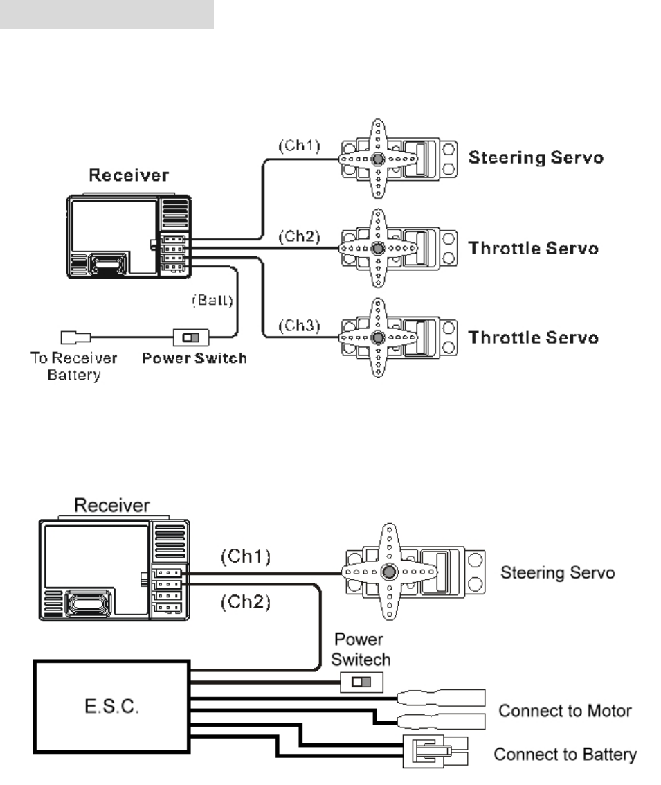
6. System Connections
Receiver and servo connections
Non-electric Model
- When you install the system in an non-electric model (or mechanical type speed control), you
should use the battery holder to supply the power for receiver
E.S.C. Installation Model
Connection Precautions
A. Installation Note
- After you installed the system, please check the receiver, servo, and battery connections,
make sure all the connections are fully inserted.
- The package contains the rubber bungs, if the slot is not in using, it can be plugged with the
bung to prevent the water splashing.
- To protect absolutely the system from water or oil damage, you can place it in a plastic bag or
waterproof box.
- Please remember this; always turn your transmitter on first and off last. Failure to do so may
result in loss of control and can damage your servos and/or linkage.
B. Receiver Note
- Keep the receiver away from motor or engine when attaching to the chassis of car or boat.
- Keep the receiver away from the power wires to prevent the interference.
- Refer you model instructions, run the antenna up the antenna tube to gain the best receiving
effect.
- DO NOT cut off the excess antenna wire, or it will shorten the operation range.
- The receiver includes a BEC (Battery Eliminator Circuit) system, which eliminates the need
for an extra receiver battery when used with a mechanical or electronic speed control. The
battery power input should not exceed 8.4V
C. Servo Note
- After you installed the servos correctly, you will need to make sure they are properly centered.
To do this, remove the servo horns and turn on your transmitter, then the power to your
receiver.
- Power on the transmitter, check that the servos are working properly.
- You will now center the trim knobs on the transmitter and replace the horns so that they are
centered.
- Be aware they may not be perfectly centered; this is OK, just get them as close as possible.
Then use the trims for fine-tuning.
D. Battery Holder Note
- Please use the AA size of dry battery or Ni-Cad battery with the holder.
- Please connect the battery holder to external power switch first and then plug the power
switch into the “BAT” slot of the receiver.
- When you use a electronic speed control or mechanical speed control with BEC, you will not
need to connect the battery.
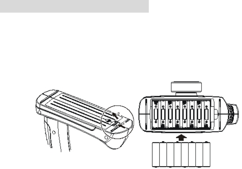
7. Transmitter Battery Installation
- Before you install the battery for transmitter, please check the transmitter power, keep it in off
position.
- Remove the cover and install the batteries as shown.
- Be careful to pay close attention to the polarity of each cell or the transmitter will not operate.
- Replace the cover back and make sure it is closed securely.
- About the battery status checking, please refer the part 8 “Transmitter Operation” to learn
about the power LED indicator.
8. Transmitter Operations
A. Antenna
- Please extend the antenna to the full length when you operating, to gain the best radio
performance.
- Be careful to handle the antenna, do not bend it.
B. Power Switch
- Stir the switch right to turn on the transmitter, and left to off it.
- Please note that turn on your transmitter first and then switch on the receiver switch to
prevent accidental runaways.
C. Power Indicator LEDs
- There are 3 LEDs to show the power status.
- Green is full power, amber is mid power and red is low power.
- When red LES is flashing, please replace the battery or charge immediately.
D. Steering Reversing Switch
- According to your model design, change the direction of the servo travel to fit the usage.
- The default position is “NOR”, if you steer right and the wheels go left, change the “ST.”
switch from “NOR” to “REV”.
E. Throttle Reversing Switch
- According to your model design, change the direction of the servo travel to fit the usage.
- You should not need to change the "THR" switch (default is “NOR”) when using an
Electronic Speed Control.
F. Steering Wheel
- Use the steering wheel to control the direction of your model.
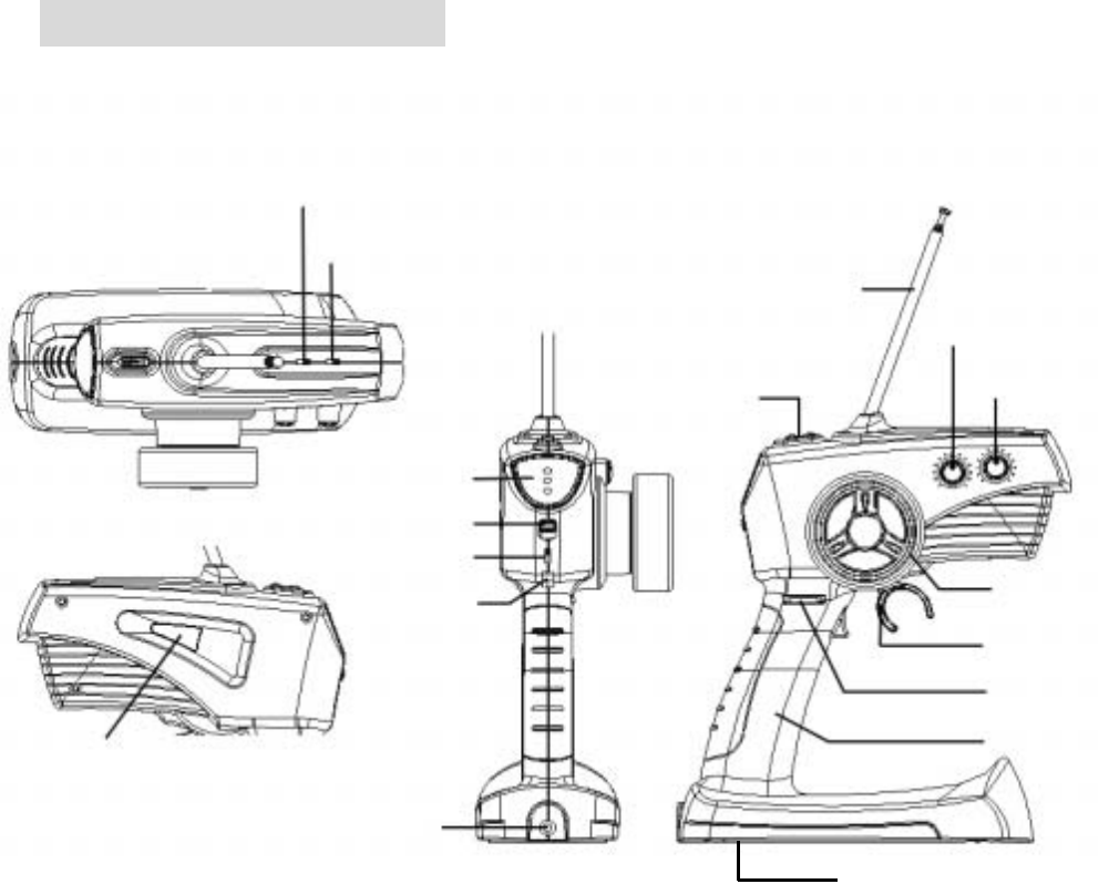
A. Antenna
D. Steering Reversing Switch
E. Throttle Reversing Switch
H. Steering Trim
I. Throttle Trim
G.Throttle Trigger
F. Steering Wheel
J. Steering Dual Rate
Holder
C. Power Indicator LEDs
O. Multi-function Switch
P. Neck Strap
Hoo
k
M. Crystal
K. Charger Jack
B. Power Switch
L.Battery Cover
N. 2/3CH Mode Switch
G. Throttle Trigger
- Use the throttle trigger to control the throttle and braking for your model.
- Pull the trigger for throttle and push it for braking or reverse. (some of the ESCs support the
Reversing function)
H. Steering Trim
- Before you use the steering trim, you should center servo horn closer to the neutral position
with the linkage, and then use the trim to fine-tune the steering.
- Adjust the steering trim to make your model running perfectly straight when the steering
wheel is centered.
I. Throttle Trim
- Use the throttle trim to adjust the braking power; this is the amount of braking that occurs
when you let go of the trigger. Be aware that too much brake may affect the servo end point
preventing maximum power.
- When using a electronic speed control, you should keep the throttle trim in the center
position.
- Do not mount the horn on the servo until you turn on the radio and center the trims.
J. Steering Dual Rate
- Use the D/R function to adjust the overall travel of the steering servo.
- Push the D/R forward with your thumb for maximum steering and pull back for the minimum
steering.
K. Charger Jack
- When you use the rechargeable batteries (ex. Ni-Cad battery), you can insert the connector of
the charger into the jack to charge the batteries.
L. Battery Cover
- Remove the battery cover to change the batteries.
M. Crystal
- Replace the crystal to change the radio frequency.
- Do not use other brand’s crystal or the transmitter won’t work properly.
N. 2 / 3 Channel mode Switch
- Use this switch to change the transmitter to 2 or 3 Channel function.
- When the mode switch set in 2 channel mode, the multi-function switch will be set in “Dual
Rate Override” trigger.
- Or the mode switch set in 3 channel mode, the multi-function switch will be set in “3rd
channel” trigger.
- About the detail operations, please refer the “Multi-function Switch” section.
- Note: When you switch the 2/3 channel mode switch, please turn the transmitter power
off first, or the setting won’t be set in. After the switch settle down, and then turn the
transmitter power on.
O. Multi-function Switch
- According to 2/3 mode switch setting, the multi-function will be set in two different function.
2 Channel mode (Dual Rate Override)
Trigger off this function, the D/R value will be set in 120%. After shutting off, the D/R
value will become to the original setting.
3 Channel mode (3rd channel switch)
- Before use this function, you should plug the 3rd servo into receiver to enable the 3rd
channel function with your model.
- Trigger this switch on, the 3rd channel servo will swing from original position to another
side.
- According to mechanical design of the model, you may switch the 3rd channel trigger
from on to off for reversing the servo direction.
P. Neck strap Hook
9. Accessory
A. Charger
- When you use the rechargeable batteries (ex. Ni-Cad battery), you can insert the connector of
the charger into the jack to charge the batteries.
- DO NOT charge the non-rechargeable batteries (ex. Dry batteries), it may cause the
unexpected explosion.
B. Sticker
- You can design any wording with the character sticker to personalize your transmitter,
receiver and servo.
Figure
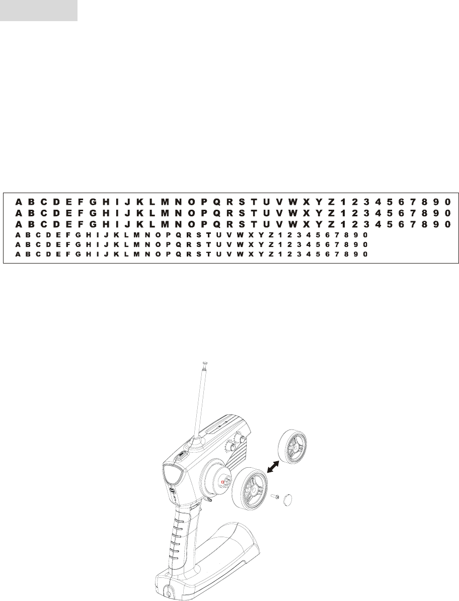
C. Steering Wheel (Big size)
- When you are racing or want to advance the sensitivity of steering, you can replace the
original steering wheel with the Big size one, it will let you operate the model smoother.
Figure
10. Reference
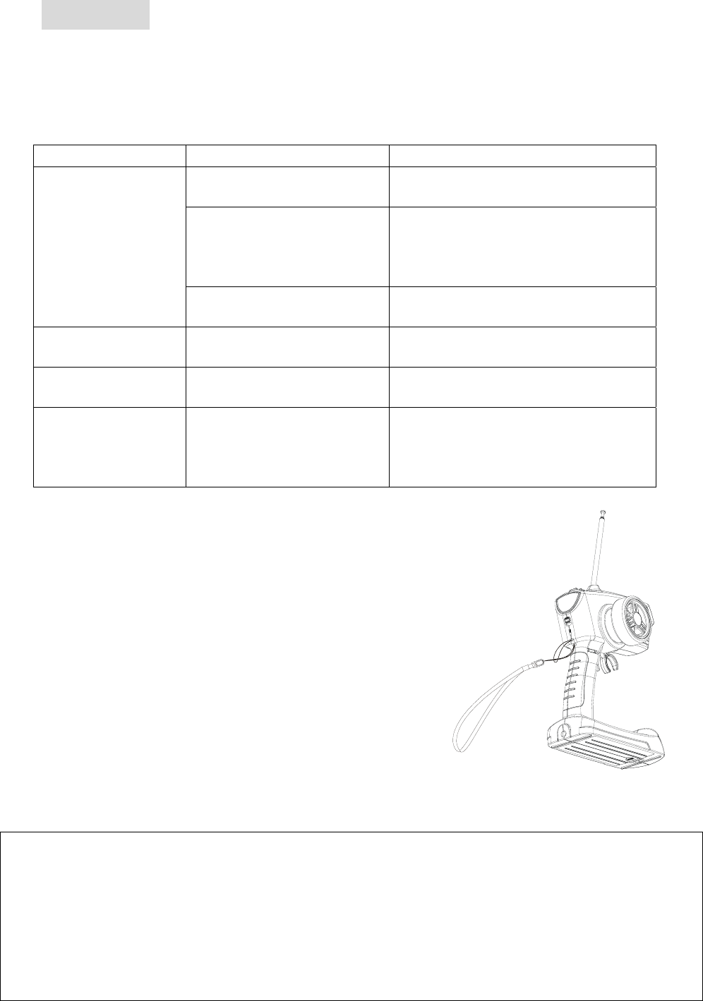
A. Troubleshooting
If your R/C system works abnormally, ex: remote range is short, transmitter malfunction, etc, please
check the table below to take the action to solve the problem, if it couldn’t solve the problem, and then
please contact your dealer to get the service.
Problem Check point Action
Batteries low Replace the batteries. Charge the
Ni-Cad batteries.
Crystal wrong, damage or
disconnected.
Please use the correct band crystal for
both transmitter and receiver. Check the
crystal connection; reinsert it into the
crystal holder tightly.
Remote range is short
Antenna disconnected.
Not extended to full length.
Screw it to the end.
Extend the antenna fully.
Servo is not running
smoothly
Receiver batteries low
Linkage binding or looseness
Replace the batteries.
Check and adjust the model.
Operation stops
intermittently
Wire disconnected.
Reinsert the connectors.
Push it tightly.
Model is glitch or
servo is running
erratically
There is another radio
operating on you channel.
The receiver antenna is near
the power wire.
Replace the crystal band.
Keep the antenna away from the power
wire.
B. User Tips
- Adjust the dual rate appropriately, it will make your
model passing the corner perfectly.
- Adjust the servo horn position and linkage so both are
parallel, it will make the servo action efficiency.
- Control your steering and throttle Nimbly, don’t push
the speed too much and overshoot when pass the
corner.
- Be careful to drive your model to prevent the crash.
Practice more on the conservative track to be familiar
with the operation, and then try the advance track.
- Have fun with your LG2-01!
警語:
根據交通部 低功率電波輻性電機管理辦法 規定:
第十四條 經型式認證合格之低功率射頻電機,非經許可,公司、商號或使用者均不得擅自變更頻率、加大功率
或變更原設計之特性及功能。
第十七條 低功率射頻電機之使用不得影響飛航安全及干擾合法通信;經發現有干擾現象時,應立即停用,並改
善至無干擾時方得繼續使用。
前項合法通信,指依電信規定作業之無線電信。低功率射頻電機須忍受合法通信或工業、科學及醫療用電波輻射
性電機設備之干擾。