Wintecronics RX61C Car Alarm System User Manual
Wintecronics Ltd Car Alarm System Users Manual
UserManual.wiki
>
Wintecronics
>
RX61C User Manual
User Manual
Navigation menu
Upload a User Manual
Namespaces
Wiki Guide
HTML
PDF
Info
Views
User Manual
Discussion / Help
Navigation
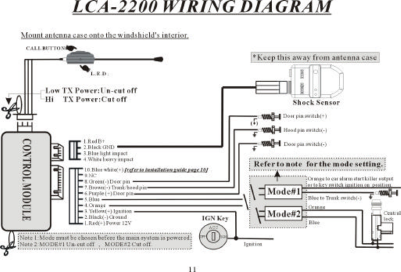
![B Type : In this type , the vehicle has neither remote-controlled central locking system or security system. Ignition switch is used to enable the main control module to operate monitoring “ON” and“Off” functions.C Type : In this type, the vehicle is installed with remote-controlled central locking system. The door lock/unlock output is used to enable the main control module to operate the monitoring ON andOff functions.※ Note:1. For A and B types , set the control module to the MODE # 1 .2. For C type, set the control module to the MODE # 2 . 【Refer to mode setting on control module on wiring diagram.】3. If mode is chosen after the main system is powered, you must set the main system at a rest . [ To do this, pull out the 10 PIN harness and re-insert it].Installation of the control moduleInstall the control module behind the dashboard, at a suitable position far from the heat source and water tank .Transmitter module/ antenna/ call button and Status LEDThe RF transmitter module is the integral part for the transmission by the control module and the push button for page-out call. The positioning of this can effect the remote transmitter range. Use thedouble-faced sticker to fix this module on either left or right upper corner of the interior of the front windshield but make sure it does not block the driver’s view and should be at easily accessibleplace for the convenience of paging out . Clean the sticker’s area thoroughly before the fixation of the module. Under “arm mode”, the status LED normally blinks slowly and acts as a warning signagainst any theft attempt. The LED will blink faster while transmitting.2 Stage Shock SensorThis senses any impact on car and reports to the main control module .It must be fixed on to the chassis or any metal surface inside the vehicle [ choose its location away from heat source, water tankand RF module to avoid interferences] . Optimize its sensitivity using its adjustment twister. Twist to 【+】 direction to make it more sensitive and to 【-】 direction to make it less sensitive. [ To testits sensitiveness , shake or strike the vehicle body with both of your palms and observe if the sensor’s light turns green for light impact and the light turns red for heavy impact. ]Hood switchThis helps the main control module to detect the hood being opened. It must be installed onto the metal being grounded. Drill a hole of 1/4 inch in diameter at the decided place for the hood switch.Make proper adjustment after installation. [ It must has negative output when the hood is opened and becomes neutral when closed.]Trunk switchMost of the vehicles have this switch. This helps main control module detect the truck being opened. It has negative output when the trunk is opened and becomes neutral when closed. [ If the trunkswitch has positive output, a relay must be added .]Door SwitchEvery vehicle has this switch. This helps the main control module detects the door being opened. [ The switch might be either positive or negative trigger depending on the vehicle] . For positivetrigger vehicle, the purple wire is used to sense door-open . But for negative trigger vehicle, the green wire is used for same purpose.Engine RunIn order for the receiver’s LCD to monitor the engine run or not [ this features is used for vehicle with remote engine start features] , the engine start circuit needs positive input to enable receiver’sLCD to show up Engine Run icon. This circuit needs connection with ignition wire. Locate the ignition wire which shows 12 V while the ignition key is turned to “ignition” or “start” position. thecontrol module uses this circuit to diagnose if the engine is running or not.※ WIRE INSTALLATION GUIDE ※10 PIN HARNESS1. Red wire: Connect this with 12 volt positive wire. Locate the positive 12V wire of the ignition switch cylinder to connect with this . This is the power supplier for main control module and isalways constant positive 12V regardless of the ignition key’s position.2.Black wire: This must be grounded and also is the main module’s ground wire.3.Yellow wire: The receiver’s LCD shows “engine run” icon when this wire has positive input. Connect this with ignition wire. Locate the positive 12V wire which will shows 12 V when the ignitionkey is turned to “ignition “ or “start “ position. The main module uses this circuit to diagnose if the engine is running or not.[ This feature is generally used for vehicle with remote engine start ]l Choice of MODE # 1 on the control module,only the orange wire is used to operate the main system “ON “ and “OFF”4.Orange wire: When this wire has constant negative input, the system enters into “lock “ mode. [ The receiver’s LCD shows up “lock” icon ] and the system enters into actual security mode 15 secafterwards .This wire is generally connected to the start kill output wire which must have negative output while its alarm system enters “ arm” mode. If the start kill wire is not available , connect567](https://usermanual.wiki/Wintecronics/RX61C/User-Guide-224171-Page-3.png)
![the orange wire with key switch ignition position wire but the disadvantage is that the LCD receiver sounds alert when the vehicle door is opened while the system enters into arm mode.5.Blue wire: When this wire has negative input, the receiver’s LCD will show up“trunk open” icon. Connect this wire with switch trigger wire.l Choice of Mode # 2 on the control module: Orange wire and blue are used to operate the main system “ON “ and “OFF” The door lock/unlock system is used to operate main system to turn “ON” and “OFF” .Connect the 4th orange wire and the 5th blue wires with the 2 wires from the central lock. The mainsystem is turned “ON” and “OFF” when remote door lock/unlock is activated. While installing ; if the lock/unlock does not conform with the lock/unlock icons on receiver’s LCD, interchange theorange and blue wire connection. For this mode, connect the trunk and hood pin wires together.6.Purple wire: If this wire gets positive input , the receiver’s LCD shows “door open” icon. If the door switch pin is positive trigger, connect this with the door switch wire. [ But if the door switchpin is negative trigger, leave the purple wire unconnected.]7.Brown wireFor mode # 1: When this wire gets negative input, the receiver’s LCD shows up “trunk open” icon. Connect this with the hood pin trigger wire.For mode # 2: When this wire gets negative input, the receiver’s LCD shows up both “ trunk open” and “ hood open” icons. Connect this with both the trunk and hood pin trigger wires.8.Green wire: When this wire gets negative input , the receiver’s LCD shows up “door open” icon. For car whose door pin trigger wire is negative, connect this with door pin wire .[ If the door pintrigger is positive, leave the green wire unconnected. ]9. Void pin10. Blue /white wire: If the mode # 2 is chosen, [ In case the door is opened with a key instead of remote control door opening , the main system might misjudge this as authorized “door open” anddisarm ] .To correct mis-adjustment problem ,locate the positive triggering wire of warning lights while remote door lock/unlock is activated (for example: parking light flash) and connect withblue/white wire.4 PIN HARNESS WIRE1. RED WIRE: This is positive output of the main system and used to supply 12 volt current for shock sensor.2. BLACK WIRE: This is the negative output of the main system and is used for ground connection with the shock sensor.3. BLUE WIRE: While the system is in arm mode; if this wire gets negative input, the receiver’s LCD shows up light impact icon.4. WHITE WIRE: While the system is in arm mode; if this wire gets negative input, the receiver’s LCD shows up heavy impact icon.5 PIN HARNESS WIREConnect the wires of RF transmitter modules with the main control modules. Cut off connection between the 4th and 5th wire [ originally is connected by the factory ] to extend the transmission rangeby increasing output power.Choice of mode # 1 or # 2 of the main control moduleThere is a black wire loop sticking out of the control case. Keep this loop intact for choice of mode # 1 . Cut this loop if mode # 2 is chosen.8910](https://usermanual.wiki/Wintecronics/RX61C/User-Guide-224171-Page-4.png)