Wiral Technologies AS 000 Wiral Lite User Manual
Wiral Technologies AS Wiral Lite
User Manual

USER MANUAL


BOOM! Thanks for purchasing Wiral
LITE and welcome to our family.
(Please take you brand new Wiral(r)
Lite slowly out of the box while
reading this imagining Morgan
Freemans voice, for a dramatic
eect)
There are those of us that like to
adventure the unexplored, go out
there with a fresh and open mind.
Those of us that go out there, with a
sense of… curiosity. We believe that
this is why you got yourself a Wiral
LITE, and we believe that this is why
you will go out there and create
videos never seen before. Because
we believe you are the future of
content creators and that the best
tools for content creations should
be available to you. Go out, be
curious, be creative, be proud and
explore the world with your Wiral
LIFE(no typo).
Go to the address or scan the QR
code below to watch a video tutorial
on how to use Wiral LITE safely:
WELCOME TO OUR FAMILY!
www.wiralcam.com/videotutorial


1. Read the complete manual before using
the product.
2. The user holding the remote controlling
the Wiral LITE is legally the operator of the
unit. The operator is responsible for safe
usage and consequences of unsafe usage of
the unit and the line. Wiral Technologies AS
is not responsible for any injury, damage of
property or harm caused by usage of Wiral
LITE and accessories.
3. Always check and follow all local
regulations and laws for operating
unmanned vehicle when using Wiral LITE.
4. Do not breach the bounds of privacy. Ask
for permission before using
Wiral LITE on private property.
5. Do not use the Wiral LITE while under the
influence of drugs or alcohol.
6. Keep control of the immediate
environment and keep Wiral LITE in line of
sight at all times when operating the unit.
Wiral LITE requires around X meters of length
for momentum to stop. Lack of attention
can result in crashing it into the end anchor
points or other obstacles.
7. Make sure the unit is powered on and the
line is tightened before mounting it on the
line. Do not loosen the line while the unit is
mounted.
8. Never exceed maximum payload of 1.5kg
(3.3 lbs)
9. Do not touch the motor when in use or
immediately aer use.
10. Stop the unit immediately if it derails.
11. Do not expose Wiral LITE for water. It is
not waterproof and cannot be used under
water.
12. Do not use Wiral LITE in wind conditions
exceeding 10 m/s, or in other severe weather
conditions.
13. Do not use in temperatures below -15°C
and above 50°C
14. Do not set up the line where it might
interfere with trac or anything that might
crash into the line (e.g. trails, roads)
15. Do not set up the line near heat source,
sharp objects (e.g. concert lights, sharp
rocks)
16. Do not set up the line on weak or
unstable anchors or anchor points that does
not have a fixed distance.
17. Always make sure the Rope Reel™ is
securely locked when tightening the rope.
18. Never overtighten the Rope Reel™ (Max
Torque Rating is X /lb X Nm).
19. Do not pull or apply pressure on a line
that is tightened.
20. Do not leave the line hanging while not
in use
21. Never use 3rd party accessories including
3rd party rope as a replacement for the
original parts.
22. Store the kit in room temperature, dry
environment and shielded from sunlight.
Maximum line strength may decrease over
time.
23. Do not use in areas with high levels of
interference (e.g radio transmission towers).
24. Only use genuine certified Wiral
replacement parts.
25. The appliance is not intended for use by
persons (including children) with reduced
physical, sensory or mental capabilities,
or lack of experience and knowledge,
unless they have been given supervision
or instruction concerning the use of the
appliance by a person responsible for their
safety
25. Always keep Wiral LITE, all accessories
and packaging out of reach of children and
infants.
SAFETY AND DISCLAIMERS
6
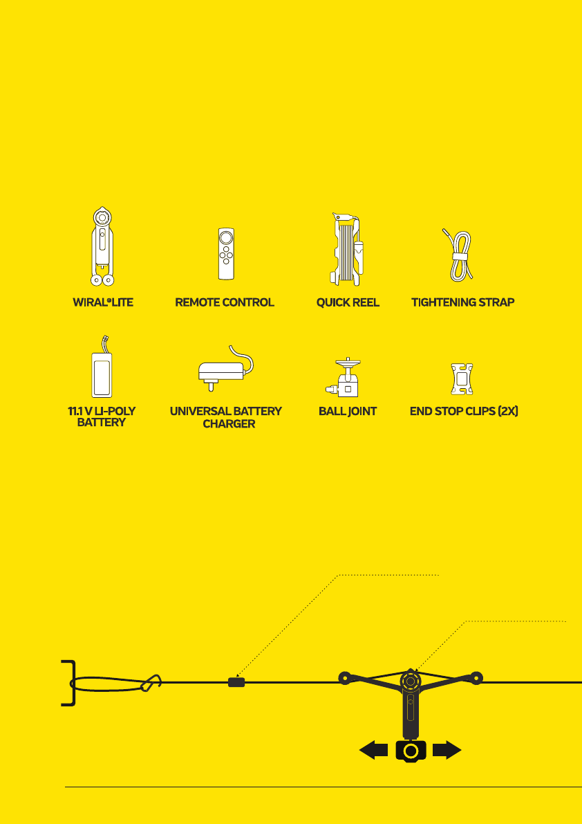
WHAT’S IN THE BOX
Please inspect the contents of your shipped package
to ensure you have received all that is listed below.
END STOP CLIP
TIGHTENING STRAP
QUICK REEL
WIRAL LITE
ROPE
REMOTE CONTROL
7
PULL
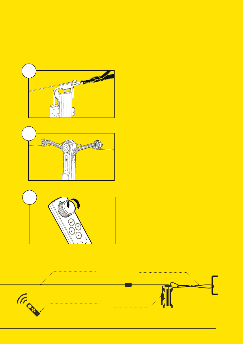
QUICK SETUP
END STOP CLIP
TIGHTENING STRAP
QUICK REEL
WIRAL LITE
ROPE
REMOTE CONTROL
1
2
3
SET UP THE
ROPE SYSTEM
READ MORE ON PAGE 8-9
READ MORE ON PAGE 10-11
READ MORE ON PAGE 12-15
PREPARE AND
MOUNT WIRAL LITE
USE THE
REMOTE CONTROL
Wiral LITE can easily be set up in less than 3 minutes. To learn
how to do it, follow the instructions on the next pages.
8
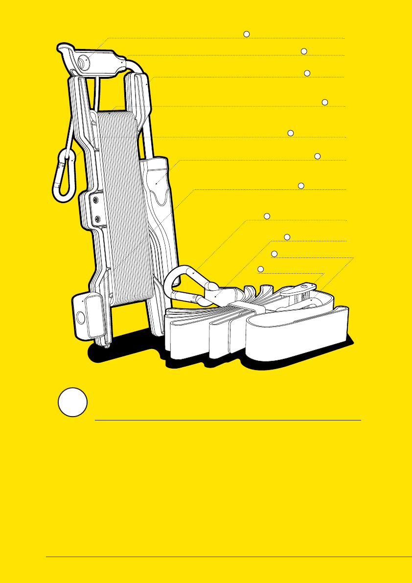
ROPE GUIDE
B
CARABINER ATTACHMENT POINT
A
ROPE
D
HANDLE
F
ROTATY KNOB
G
ROPE CARABINER
E
ROPE REEL
C
LARGE STRAP CARABINER
H
TIGHTENING STRAP
I
TIGHTENING BUCKLE
K
SMALL STRAP CARABINER
J
QUICK REEL™
The Wiral LITE kit comes with the Quick Reel™ that
makes it possible to set up the line in just a few
minutes. The Quick Reel™ consists of a reel
for handeling the rope and a tightening
strap for connecting and
tightening it.
1
9
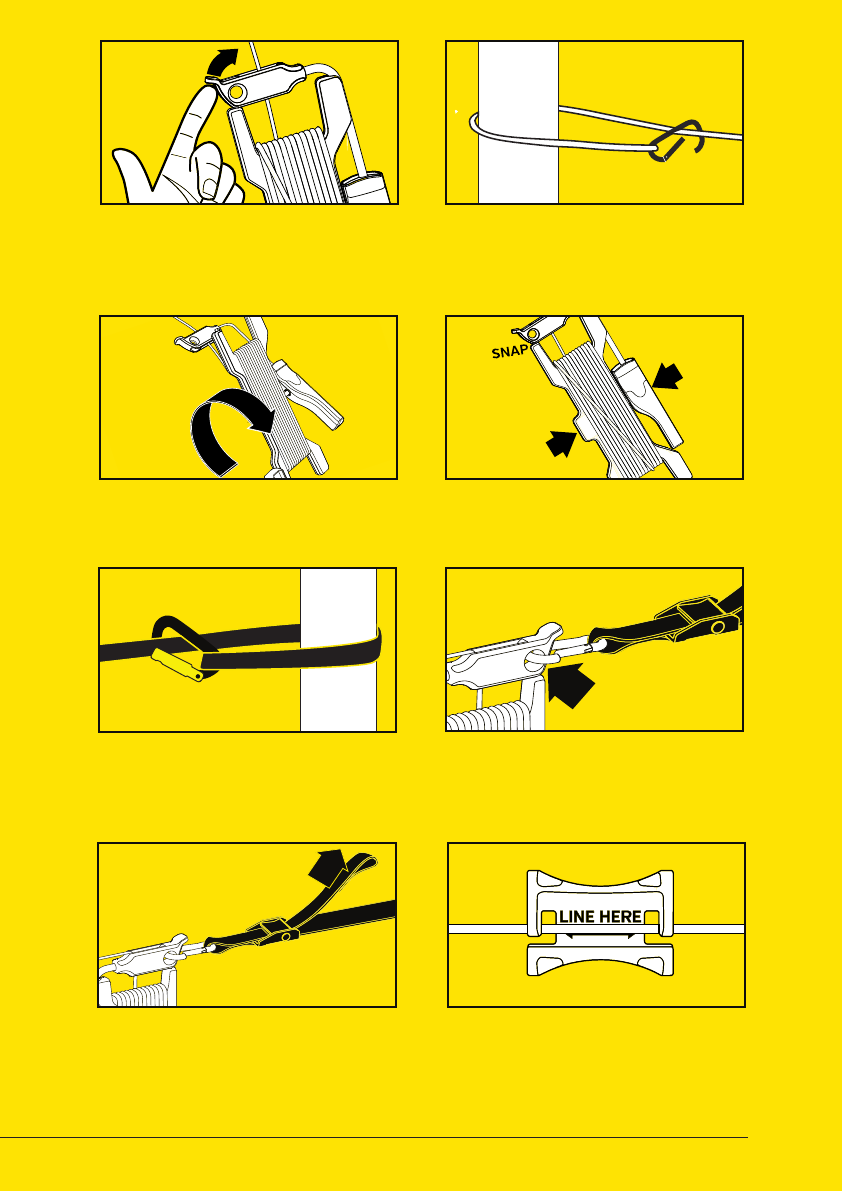
01 UNLOCK QUICKREEL™
03 UNWIND ROPE
05 FASTEN STRAP
07 TIGHTEN STRAP 08 MOUNT END STOPS
Press rope guide to unlock Quick
Reel™ and unwind the rope.
Unwind the rope untill you are close
to the next attachment point.
Place the tightening strap around
the second attachment point, and
attach the large strap carabiner.
Tighten the system by pulling the
end of the strap with a maximum
load of 40 kg.
Mount the physical end stops close
to the attachment point on each side.
See next page.
Put rope carabiner around attach-
ment point and attach to the rope.
See number marks on the strap.
Lock the Quickreel™ when you are
close to the second attachment point.
Connect the small strap carabiner
to the Quick Reel™ rope guide.
02 ATTACH CARABINER
04 LOCK QUICKREEL™
06 ATTACH STRAP
PULL
PULL
PUSH
PUSH
10
ROPE
END STOP CLIP
Minimum 3 m from the end
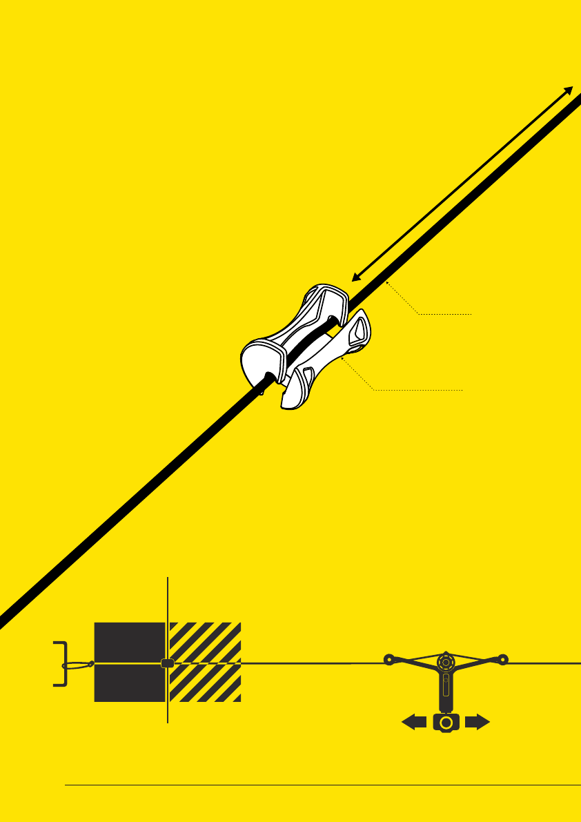
MOUNTING OF END STOP CLIPS
The kit includes two end stop clips. The clips should be
mounted on to the rope in a recommended distance from
each attachment point. The distance can be found in
the table on the next page. This will help avoiding
Wiral LITE crashing into the attachement
points. When the end stop is mounted,
it will either derail or stop
the unit before it is
reaching the end
of the line.
BREAKING
DISTANCE
END
STOP
CLIP
SAFETY
ZONE
BREAKING
DISTANCE
END
STOP
CLIP
SAFETY
ZONE
11
BREAKING
DISTANCE
END
STOP
CLIP
SAFETY
ZONE
BREAKING
DISTANCE
END
STOP
CLIP
SAFETY
ZONE
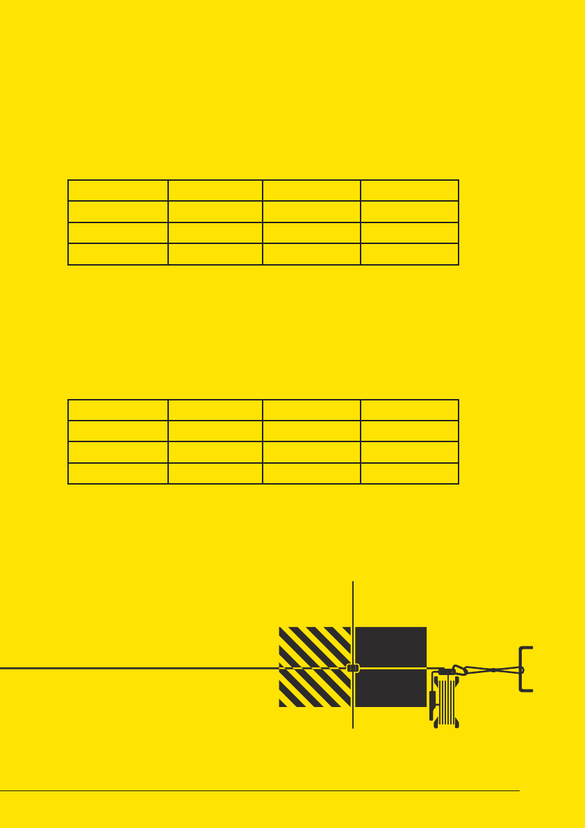
BREAKING DISTANCE AND SAFETY ZONE
SAFETY ZONE
BREAKING DISTANCE
The end stop clip should be mounted with a safety zone between it
self and the end of the line to avoid Wiral LITE from crashing into the
attachment point. The length of the zone will vary with the weight of the
camera used.
Maximum breaking distance of Wiral LITE will be dierent based on the
weight of the camera that is used.
0 - 500 g 500 - 1000 g 1000 - 1500 g
Horizontal
30° Incline
30° Decline
*The values are estimates, and may vary with environmental conditions.
0 - 500 g 500 - 1000 g 1000 - 1500 g
Horizontal
30° Incline
30° Decline
*The values are estimates, and may vary with environmental conditions.
12
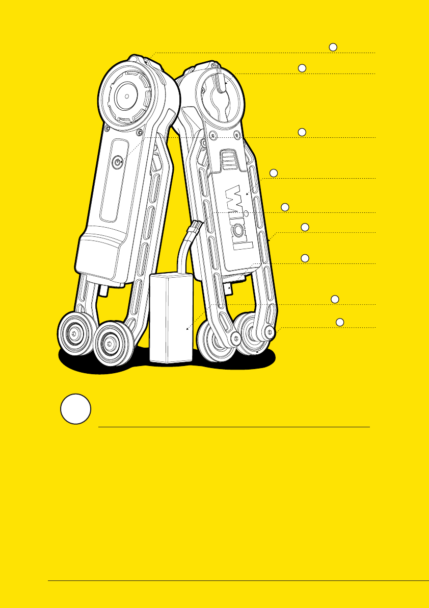
MAIN UNIT
LOCK PIN
A
ON / OFF BUTTON
C
BATTERY COMPARTMENT
D
LOCK PIN PULLER
B
BATTERY
H
PULLEY
I
CAMERA MOUNT
G
CAMERA MOUNT
F
BATTERY CONNECTOR
E
Aer mounting the line, it is time to prepare
the main unit, including the batteries
and the camera that is going
to be attached.
2
13
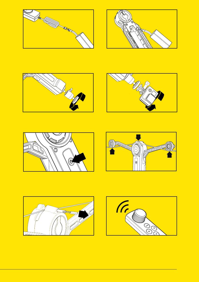
01 CHARGE BATTERY
04 MOUNT CAMERA
02 INSERT BATTERY
07 CLOSE LOCK PIN 08 CONNECT TO REMOTE
Charge battery using the charger
included in the kit. Read more
on page 18 - 19.
Mount your camera on to the
universal mount screw.
Insert battery into Wiral LITE and
connect it to the power plug. The
unit automatically turns on.
Secure the unit by opening the lock
pin, let the line pop into place. Make
sure that the line is place in the
groove.
If the remote is switched on, the
remote will connect automatically.
Mount the ball joint to be able to
point your camera in any angle.
Mount the unit on the line by placing
the line between the two pulleys and
the drive wheel.
Power on by pressing the power
button. A light in the button
indicates if it is on.
03 MOUNT BALL JOINT
06 MOUNT ON LINE
05 POWER ON
14
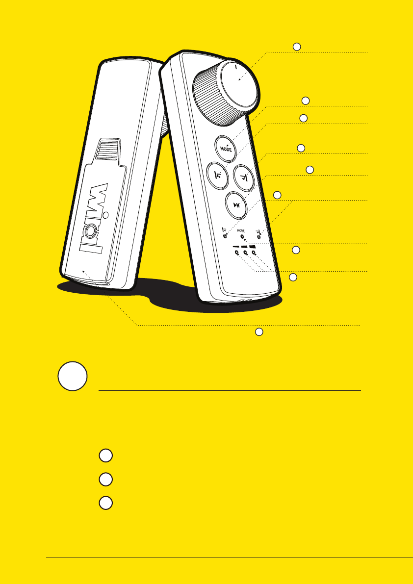
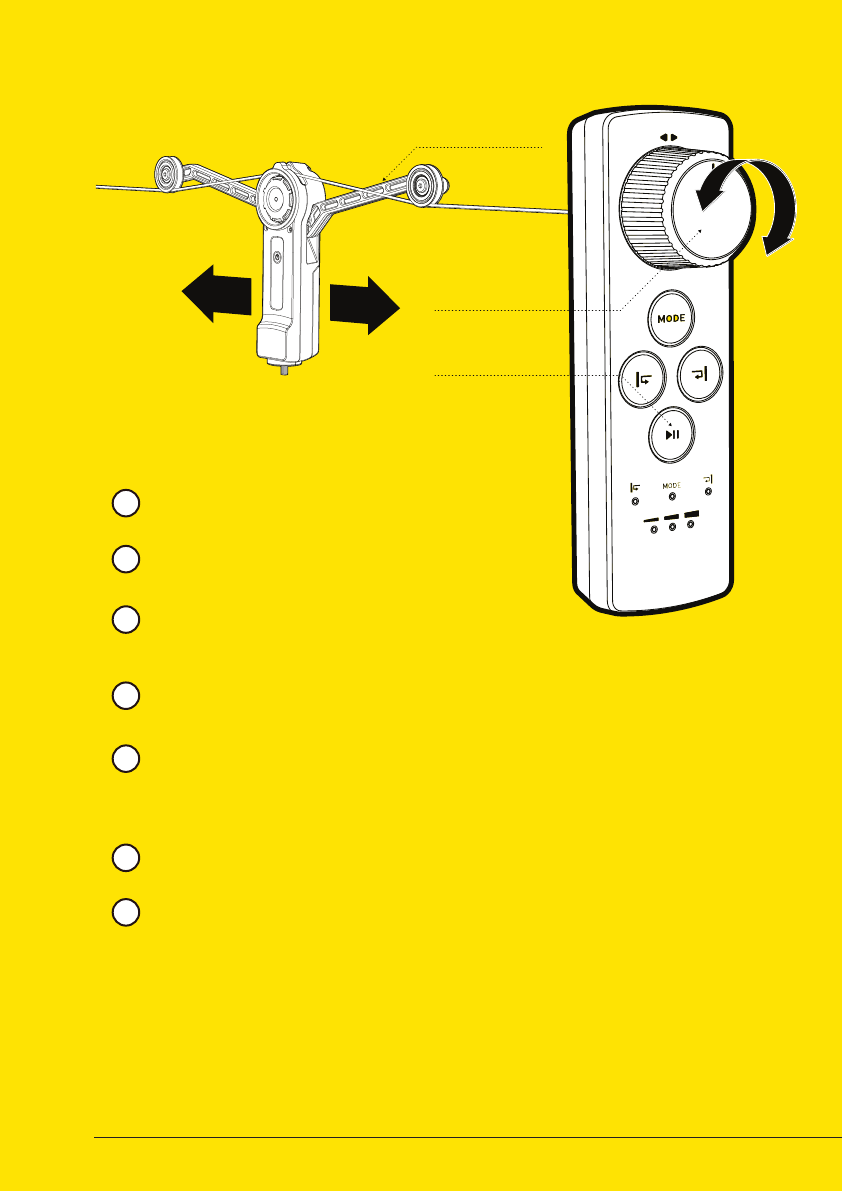
CONTROL WHEEL
MODE BUTTON
SET END STOP 1
SET END STOP 2
PLAY / PAUSE
MODE INDICATOR
END STOP INDICATORS
BATTERY COMPARTMENT
SPEED & BATTERY
INDICATOR
A
B
C
D
E
F
G
H
I
REMOTE CONTROL
Normal Mode: Control the speed from 0 to 0.7 m/s directly by
turning the speed wheel. (See more on page 16)
Wiral LITE can be operated by using the remote control included in the
kit. The remote control can control speed and acceleration, set digital
end stops, and give feedback through six LED lights. Controlling the
unit can be done in three dierent modes:
Sport Mode: Control the speed from 0 to 9 m/s directly by
turning the speed wheel. (See more on page 17)
Time lapse Mode: The unit moves slowly back and forth
between the electronic end stops in speeds up to 0.01 m/s. (See
more on page 18)
1
2
3
3
15
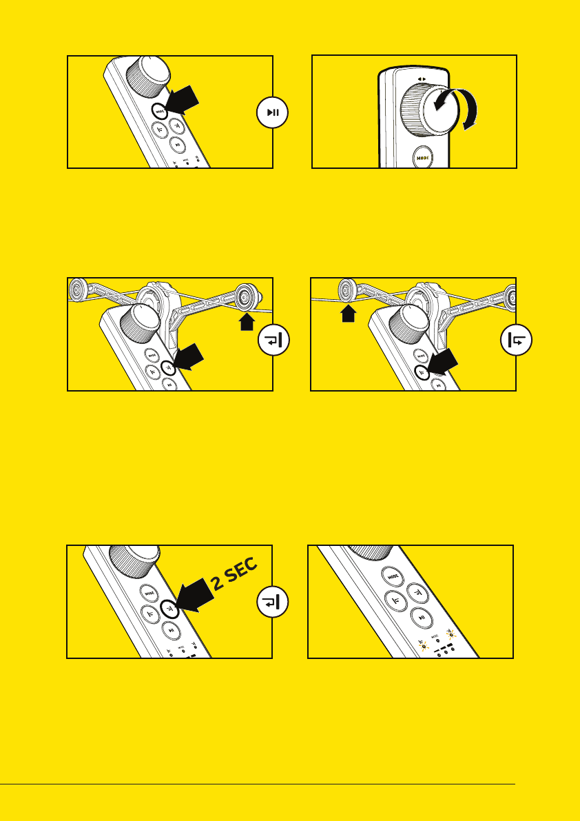
01 POWER ON
03 SET DIGITAL END STOP
02 CONTROL MOVEMENT
04 SET SECOND END
06 END STOPS NOT SET
05 REMOVE END STOP
Press the Mode Button to turn on
the remote control. The Mode LED
will turn on.
Set digital end stops by moving
the main unit to the point you
want it to automatically stop and
press the end stop button. The
yellow end stop button will set a
digital end stop in the direction of
the arm marke with a yellow stripe.
Rotate the Speed Wheel to move
the main unit. Rotating towards
the yellow arrow, will move the
main unit in direction of the arm
marked with a yellow stipe.
Move the main unit to the second
point you want it to automatically
stop and press the opposite end
stop button. The main unit will
now only move in between theese
points. Be aware that the end stops
might dri. They should be reset
aer emergency stops.
Setting digital end stops is highly
recommended. In automatic
mode the indicators will blink if
the end stops are not set.
Remove end stop by holding the
end stop button for 2 seconds.
To replace an end stop, just click
the end stop where you want to
place it.
16
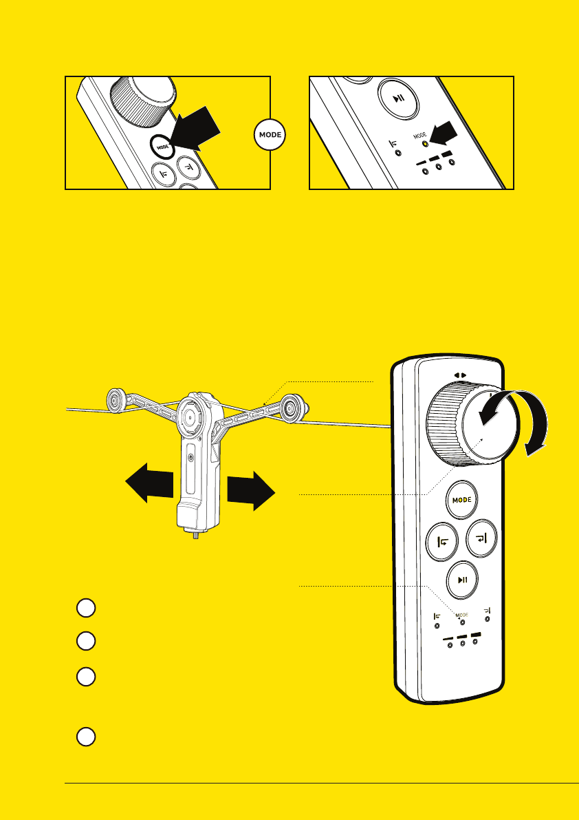
DIRECTION
MARKS
ON ARM
SPEED WHEEL
MODE INDICATOR
NORMAL MODE
CHANGE SPEED MODE
Control the speed from 0 to 0.7 m/s
directly by turning the speed wheel.
When in Normal Mode, the mode
indicator will fade slowly in and out.
Moving the speed wheel clockwise
(towards the yellow arrow) will make the
main unit move towards the side with
yellow print.
When the speed wheel is released, the
unit will stop.
01 CHANGE MODE 02 MODE INDICATION
Remote is automatically set to
normal mode when turned on.
Change modes by pressing the
mode button.
Normal Mode: Mode indicator LED
is blinking slowly.
Sport Mode: Mode indicator LED
is blinking fast.
Time Lapse Mode: Mode indicator
LED is continously lit.
2
1
3
4
17
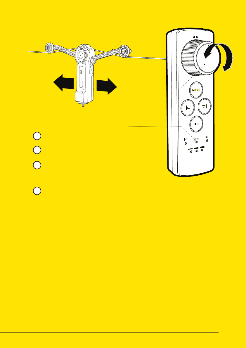
DIRECTION
MARKS
ON ARM
SPEED WHEEL
MODE INDICATOR
SPORT MODE
Control the speed from 0 to 9 m/s
directly by turning the speed wheel.
When in Sport Mode, the mode
indicator will fade quickly in and out.
Moving the speed wheel clockwise
(towards the yellow marks) will make the
unit move towards the side with yellow
print.
When the speed wheel is released, the
unit will stop.
2
1
3
4
18
DIRECTION
MARKS
ON ARM
SPEED WHEEL
MOVE / PAUSE
BUTTON
Control the acceleration by turning the
speed wheel.
When in Time Lapse Mode, the mode
indicator is continously lit.
Moving the speed wheel clockwise
(towards the yellow marks) will accelerate
the unit towards the side with yellow print.
When releasing the wheel, the unit will
continue in the same speed.
2
1
3
4
TIME LAPSE MODE
Pause the unit by pressing the move /
pause button on the remote. The speed
can be adjusted both in paused and
moving state.
To reset the speed to zero, click the
play/pause button twice.
Unit restarts when play/pause button
is pressed for the second time
5
6
7
19
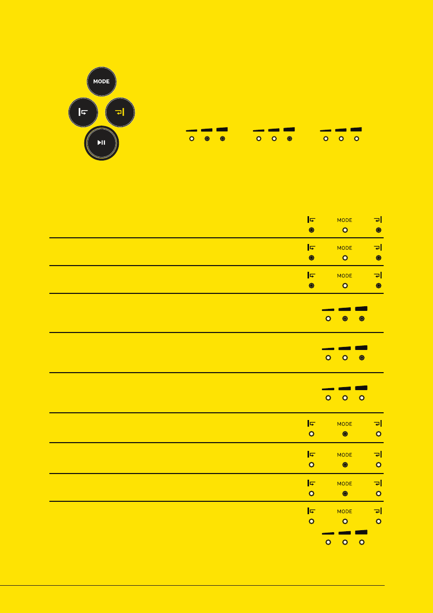
CHECK BATTERY STATUS
LED STATES
NORMAL MODE
SPORT MODE
END STOP 1 AND 2 SET
END STOP HIT
TIME LAPSE MODE
END STOP NOT SET
NOT CONNECTED
LOW SPEED (BLINKING FASTER AND FASTER)
MEDIUM SPEED (BLINKING FASTER AND FASTER)
HIGH SPEED (BLINKING FASTER AND FASTER)
Mode indicator is fading slowly in and out.
Mode indicator is fading quickly in and out.
When end stop indicators are lit, digital end stops are set
Pulsating LEDs when the unit is place on a set end stop
Mode indicator is continously lit.
I digital end stops are not set in Time Lapse Mode, LEDs will blink
If the remote is not connected to the main unit, all six LEDs
will blink at the same time.
0 - 16 meter per hour in Time Lapse Mode
16 - 32 meter per hour in Time Lapse Mode
32 - 48 meter per hour in Time Lapse Mode
To check the battery status of the main unit, hold the
play / pause button for 2 seconds. The status will be
displayed in the LED below.
BATTERY LEVELS
LOW
7 - 25 % 25 - 60 % 60 - 100 %
MEDIUM FULL
20
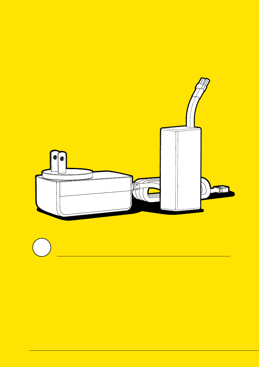
BATTERY/CHARGER
Wiral LITE is using a 11.1V rechargeable LiPo battery, that
can be recharged by using the charger included in
the kit. Be sure to read the instructions for
use on the next page before using
both the battery and
the charger.
4
21
Risk of explosion if battery is
replaced by an incorrect type.
Dispose of used batteries according
to the instruction.
CAUTION
1. Read this whole document (Wiral
LITE User Manual) before using or
charging the battery.
2. Never puncture, deform,
disassemble, shock or short circuit
the battery.
3. Stop using or charging the battery
if it swells up, the temperature
exceeds 60°C, it leaks or anything
abnormal happens.
4. Keep battery out of reach of
children.
5. Never use a wet battery.
6. Keep away from heat and fire.
SAFETY AND DISCLAIMERS
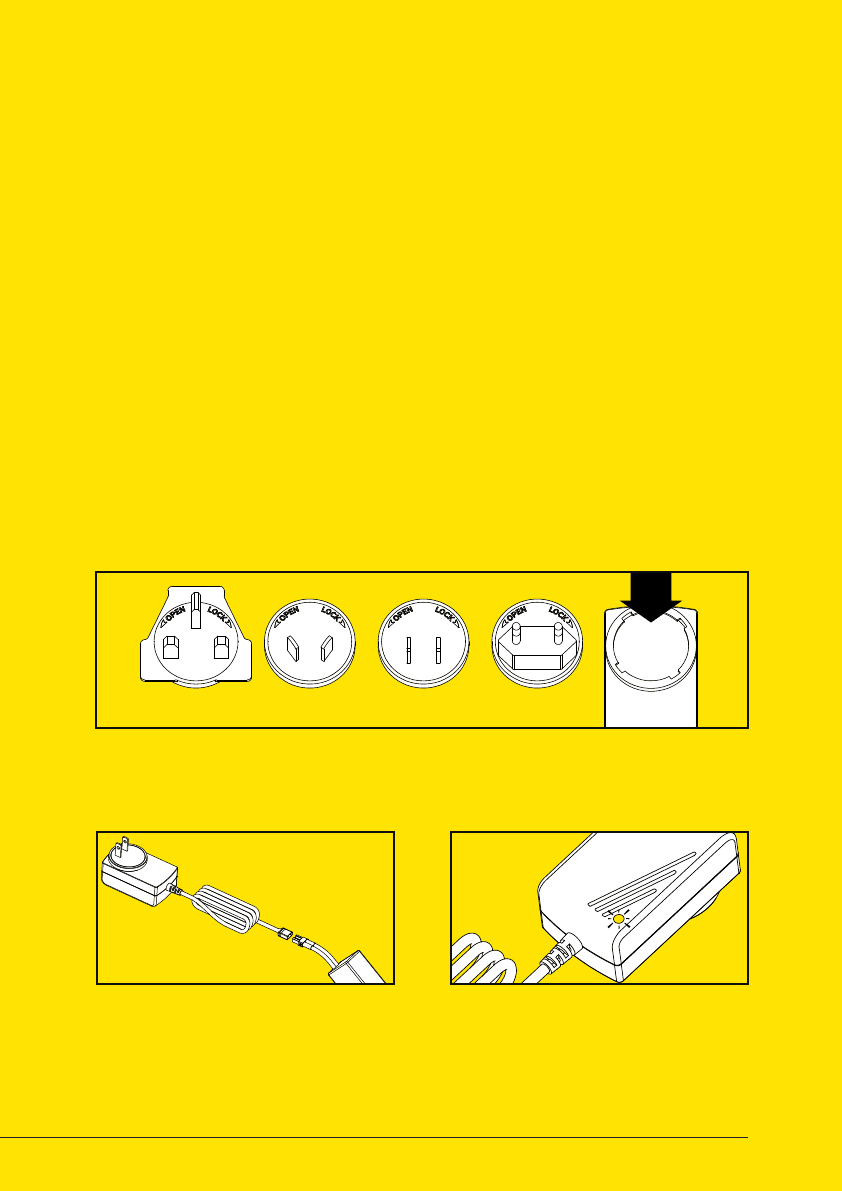
01 SELECT AND MOUNT PLUG
03 WAIT FOR GREEN LIGHT02 CONNECT BATTERY
The charger comes with four dierent interchangeable plugs. Select the
correct one for your area, and insert it into the charger.
When the battery is fully charged,
the LED indicator will change from
red to green. The battery is now
ready to use.
Connect the battery to the
charger, and plug the charger into
a power outlet.
ULSAAUK CE
7. Only use the original Wiral LITE
charger.
8. The user takes the full
responsibility of using this battery.
Manufacturer: ABP Group Ltd.
Input: 110-240 V
0.5 A max
Output: 12.6 V
1000 mA
SPESIFICATIONS

When running Wiral LITE with high loads and
in high speed for a longer period, the main
unit might get warm. To protect the product
from possible damages, it will automatically
slow down the speed for a short period to
cool down. If the problem continues, the unit
will stop.
When using Wiral LITE over time, the rope
will wear and tear. To avoid to much damage
on the rope, there are some precautions that
can be taken.
1. Do not use steeper lines than 30 degrees.
2. If hitting obstacles, the support pulleys
might derail. Be sure to place them in the
correct position before you continue.
3. When mounting Wiral LITE, be sure that
the line is placed in the drive wheel groove. If
not, the line will be damaged.
If you are experiensing connection or control
errors while using Wiral LITE, a solution
could be to do a factory reset to recalibrate
the unit. The reset is a quick and simple
operation:
1. Press and hold the on / o button on the
main unit while connecting the battery.
2. If done correctly, the motor should start
running slowly to calibrate the unit.
3. When the motor stops, the unit is ready to
use.
OVERHEAT PROTECTION
AVOID ROPE WEAR
WIRAL LITE FACTORY RESET

If you need more information about Wiral
and Wiral LITE, check out
www.wiralcam.com
To find all information on using Wiral
LITE, such as FAQ, tutorials and support
information, go to
www.wiralcam.com/support
To read more about warranties, and general
legal information for Wiral, visit
www.wiralcam.com/legal
USEFUL LINKS

www.wiralcam.com
© Wiral Technologies AS. All rights reserved.
This content is subject to change.
Download the latest version at
www.wiralcam.com/support