Wireless Cables ACC1300 Bluetooth Serial Interface User Manual
Wireless Cables Inc. Bluetooth Serial Interface Users Manual
Contents
- 1. User Manual
- 2. user manual update
User Manual
AIRcable User Manual
AIRcable Serial
Model 1302
Wireless Bluetooth to Serial Adapter
User Guide
Rev 0.95
December 7, 2004
Thank you for purchasing an AIRcable. Your satisfaction is very important to us, so please read this guide
before installing your AIRcable modules. We’d appreciate your feedback.
For more information and instructions or for support please visit our website at http://www.aircable.net
The AIRcable product is a Bluetooth to serial adapter for cable replacement functions with user accessible
command line for configuration. The AIRcable product is Bluetooth 1.1 certified.
A
IRcable modules are intelligent and run firmware-based onboard Bluetooth connection software. There is
no need to install and configure extra software to establish a wireless connection. Because the AIRcable is
designed to replace physical connections, you can run the same software that would support a physical
cable.
Each module has a button accessible through a hole in the device which is used to pair two modules to become a point-to-point
“
Wireless Cable™”. During this pairing process, make sure no other Bluetooth device is discoverable within range (approx. 10 meters).
Each module has one power LED (green) which shows that the firmware is running correctly and a connection LED (blue) that shows
the status of a connection. The connection LED is on solid if a connection to another device is active. Otherwise it is blinking or it is off.
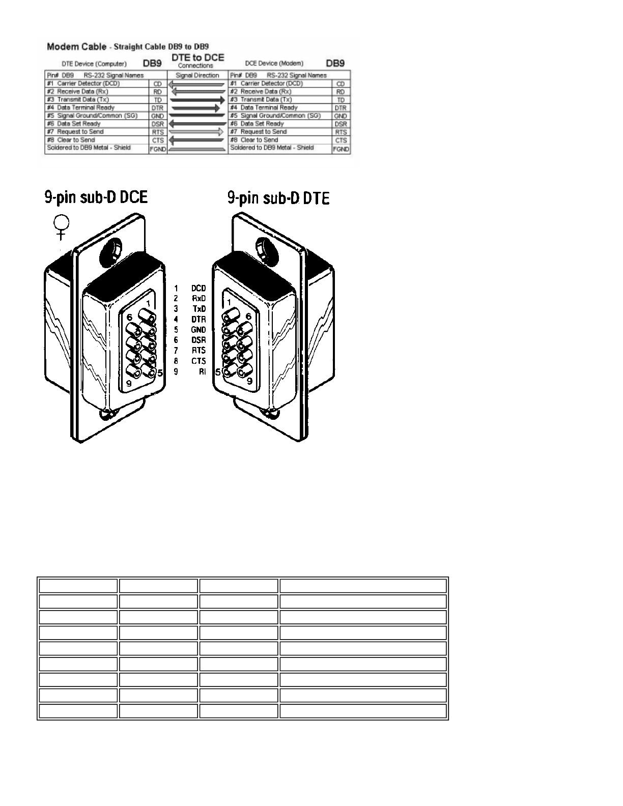
The AIRcable Serial is fully Bluetooth 1.1 certified and is compatible with all other Bluetooth 1.1 compatible devices. The AIRcable
Serial is compilant with RS-232 serial industrial standard EIA-232-E. There are two different versions available: The DTE has a Sub-D 9
pin female connector and the DCE has a Sub-D 9 pin male adapter.
The AIRcable Serial supports all modem control signals, including DTR, DSR, and DCD. Data flow control is implemented using
RTS/CTS handshake. Data mode by default is 8 bit, no parity, one stop bit.
NOTE: Because the devices implement hardware handshake, the
RTS/CTS lines have to be connected
or it
must be switched
off
. If your device does not support hardware handshake you must switch off hardware handshake with the 4th switch on the AIRcable
switch (down) in order for the AIRcable Serial to work properly.
Pin 9 can also be used for powering the AIRcable Serial module. Apply 5-15V DC, plus to pin 9, GND is pin 5 instead of using an
external power adapter.
Pa
g
e 1 of 7AIRcable User Manual
Baudrate Selection and Switches
The AIRcable Serial provides switches accessible from the top to select the baud rate. Switch up is on or '1'. Down means off or '0'.
The 4th switch is for hardware handshake. Up means hardware handshake is switched on, down means off.
SW1 SW2 SW3 Baud Rate
0 0 0 31.25 kbit/s
0 0 1 19.2 k
0 1 0 4.8 k
0 1 1 56.7 k
1 0 0 4.8 k
1 0 1 38.4 k
1 1 0 9.6 k
1 1 1 115.2 k
Pa
g
e 2 of 7AIRcable User Manual

Configuration
When you receive an AIRcable Serial, the device must be configured.
A
IRcable devices support these modes:
zCable Mode
zService Mode
zManual Mode
Cable Mode
In cable-mode, two AIRcable devices are paired together and create a bond so no other device can interfere.
To pair two AIRcables use this simple procedure:
1. Press and hold the pairing button for 5 seconds. The AIRcable module automatically configures itself and starts in slave mode.
The power LED (green) will be on again and the connection LED (blue) starts flashing rapidly.
2. Do this on both devices that are going to be paired.
3. On one device press the pairing button again (short click) to change the mode to master.
At this time the two devices will find each other, pair and establish a connection.
4. The pairing information has been stored in flash and the two AIRcable modules will connect automatically when they are
powered on. No other device can connect to either AIRcable.
A
dvanced Modes
The AIRcable Serial can be set into various advanced modes. Use the command line interface to change into these modes.
zService-Slave mode
zService-Master mode
zManual mode
Using the Command Line Interface
The command line interface is available through the serial interface before the AIRcable device is connected. This means that the
connection LED must be either blinking or off.
The serial parameters for the command line interface are fixed at:
• 115200 baud (AIRcable for Motorola is at 57600 baud)
• no parity, one stop bit, 8 bit data, hardware handshake enabled
Use a serial null-modem cable to plug the AIRcable Serial with a male type DB9 connector into a PC.
Each command starts with a “^A” (control-A or 0x1) character, then follows one of the commands listed below in all caps letters and
finishes with a single <CR> (carriage return or 0xd). The command has to be completed within 3 seconds. Otherwise the received
characters are deleted and ignored. All commands respond with an "OK".
Be aware that some commands in some states require the device to reset. They are marked with (*). This process will take a few
seconds during which the AIRcable will not respond to any commands. The power light will go out briefly.
Service-Slave Mode
In the Service-Slave Mode, the AIRcable allows other Bluetooth devices to connect to it. This mode can be used to allow a Palm with
Bluetooth or a Laptop with Bluetooth support to connect. The main advantage of this mode is that it allows several devices to connect
to it as oppose to the previously described point-to-point cable modes.
Pa
g
e 3 of 7AIRcable User Manual

In order to switch the AIRcable module into “Service-Slave Mode” use the command line interface detailed below. This is just an
example. Please adjust the commands to the situation you need, including your security needs.
• Reset the AIRcable to the factory default value and delete all pairing information
"^A Z <CR>
• Change the name of the device
”^A N AIRcable <CR>”: set the name to AIRcable. The name has to be exactly 8 characters long. Use spaces to fill up.
• Configure the PIN number. Either a fixed 2-5 digit number or an automatically generated 5 digit ID that will be added to the name to
uniquely identify multiple AIRcables.
”^A P 1234 <CR>”: set pin number to 1234, require authentication
”^A PU <CR>”: generate a unique 5 digit pin number and append it to the name
”^A PD <CR>”: disable authentication, the AIRcable allows connection without PIN. It will keep the pin number and the name.
• Configure the supported Bluetooth profiles (see details below):
”^A DDS <CR>”, set discoverable SPP profile.
• Switch to mode to “Service-Slave Mode”
”^A A3 <CR>
Service-Master Mode
The Service-Master Mode is the counter part to the Service-Slave Mode. It can be used as a master to connect to several Bluetooth
devices which are in range, one at a time. The advantage is that it does not require pairing or bonding with the other end. It is a truly
automatic-connect to many other Bluetooth devices. Certainly you can configure automatic pairing with a PIN number of your choice.
For example, it can connect to Bluetooth scanners without pairing it to a particular one. In this case the Service-Master AIRcable would
be configured with the PIN number of the scanner (often “0000”) with authentication enabled and it will automatically connect to the
first scanner it finds. You can change the scanner without changing the configuration.
The Bluetooth Service-Master Mode can also be used to connect to a number of AIRcable devices in Service Mode. This is designed for
field usage where the AIRcable Service modules are stationary and the AIRcable Master-Service is mobile going from one Service
module to another. Again this is an example. Adjust to your needs.
• Configure the PIN number that corresponds to the devices you want to connect to, either a fixed 2-5 digit number or an automatically
generated 5 digit ID that will be added to the name to identify the AIRcable.
”^A P 0000 <CR>”: set pin number to 0000, require authentication
• Disable authentication if the devices you are connecting to don’t require authentication: “^A P D <CR>”
• Switch to mode to “Service-Master Mode”
”^A A4<CR>
Manual Mode
The manual mode is designed to give Bluetooth support to devices that cannot run a full Bluetooth stack. The command line interface
is a collection of the simple most common Bluetooth commands. It allows the discovery of other devices, pairing, inbound slave and
outbound master connections and disconnect by software.
Y
ou should understand Bluetooth before you can use the manual mode. Please contact us if you have any questions.
Disconnect by Software
Once a connection is established the command line interface is no longer available since all input and output is routed through
transparently to the other end.
In this mode it is possible to disconnect a link programmatically. Depending on the type of device (DTE, DCE or USB) your software
would disable either the DTR or the DSR line, whichever is an input on the AIRcable side.
zOn the AIRcable Serial DCE (module with male type DB9 connector) the input pin is pin 6 of the DB9 connector (DSR). Once
this pin becomes inactive, the connection is dropped.
zOn the AIRcable Serial DTE (module with female type DB9 connector) the input pin is pin 4 of the DB9 connector (DTR). Once
Pa
g
e 4 of 7AIRcable User Manual
this pin becomes inactive, the connection is dropped.
zOn the AIRcable USB module, the program should use the DTR line to disconnect the link.
zOn the AIRcable for Motorola, close the port and it will automatically disable DTR and disconnect.
List of commands
“H” Shows status of the AIRcable
“B” Print its own BT address: “ADDR: 1A2B3C4D5E6F”
“O” Print or set “Class Of Device”.
Example: “OC20104” sets class of device to INFO+MODEM+NET, major PC, minor
DESKTOP, see "Bluetooth Assigned Numbers" documentation (*)
“P” Display PIN number: "PIN: 12345"
“P12345” Set PIN number to “12345”, and enable authentication. Pin number can be
between 2 and 5 digits long.
“PD” Disable authentication but keeps the PIN number if another device asks for it. For
slave mode only.
“PU” This command creates a unique 5 digit PIN number and appends it to the name.
"E" Disable encryption mode: "encryption disabled"
"E1" Example: enable encryption mode.
“N” Returns the name of the device: "AIRcable"
“NAIRcable” Set name to AIRcable, name has to be exactly 8 characters, fill up with space if
required name is shorter.
“I” Do an inquiry scan for default 11 seconds. The following commands are useful
only in manual mode. Upon start it will respond with: "INQUIRING". At the end it
will print "OK".
“I90” Do an inquiry scan for 90 seconds, number must be between 1 and 90 seconds.
The result for example looks like: “1A2B3C4D5E6F, class 0xC20104, name
AIRtag 12345”.
“CS1A2B3C4D5E6F” Connect as master command. Use authentication as configured. Example: connect
to this BT address at port serial. Second letter specifies the port to connect to: S-
serial D-dialup L-lan or O-obex. The command responses with "CONNECTING",
then "CONNECTED" or "FAILED".
“R1A2B3C4D5E6F” Manual pair request. This pairs the AIRcable with the partner specified with the
address. It uses the PIN number configured. The the AIRcable stores the link key
it receives to be used in a subsequent connect command. The command
responses with "PAIRING" and then "OK" or "FAILED".
"L" Read the link key that was stored by previous commands.
"L1234567890ABCDEF..." Set the link key. These are 32 hex numbers.
“D” Display the services enabled, it is a hex number that is or’d from these services:
serial 0x8, dialup 0x4, lan 0x2, obex 0x1.
“DDSDLO” Set discoverable mode and advertise SPP (serial), DUN (dial-up), LAN, OBEX
profiles. First specify if the device should be discoverable “D” or not “U”, then
select the profiles: S-serial D-dialup L-lan or O-obex. (*)
“DU” Make device undiscoverable, keep the selected profiles.
“S” Slave connect command. This is a one time slave command for 11 seconds. After
that the devices is in manual mode again. The command responses with "OPEN"
and then "CONNECTED" or "FAILED".
“S20” Start slave connect for 20 seconds. If authentication is enabled the PIN number
configured is being used. You can specify up to 90 seconds.
“A” Display automatic mode (manual=0, master=1, slave=2, service=3, service-
master=4)
“A0” Manual mode
“A1” Cable-slave mode. The AIRcable becomes discoverable and will be in pairing
mode if no pairing information has been stored. Then it will be not discoverable
and will allow connections only from the paired partner. In this mode, only the
Pa
g
e 5 of 7AIRcable User Manual
Note that the (*) in the description means that this command may reset the processor. Wait for 3 seconds before issuing another
command.
Operational Specification
Range: 10m in open office conditions
Electrical Requirements:
Power consumption
SPP profile is active.
“A2” Cable-master mode: do inquiry first, then pairing with the configured PIN number,
then connect as master (not discoverable).
“A3” Service-slave Mode: Use the authentication, profiles, pin number and name
configured before. (*)
“A4” Service-master mode. If authentication is enables it first discovers a partner, tries
to pair with it and makes a connection. If authentication is disabled, it discovers a
partner and tries to connect to it. It uses the PIN number configured before.
"U" UART configuration command. Display the settings in hex: "UART: 0x6". It is an
add up of the following: external switches enabled: 6, even parity: 4, odd parity:
2, two stop bits: 1.
“UN1E” Configure the UART: First letter is parity: none=N, E=even, O=odd. Second is
number of stop bits: 1=one, 2=two. Third letter enables the external baud rate
switches: external=E, internal=I.
“UE2I” Example 2: Even parity, 2 stop bits, internal baud rate settings.
"UO1E" Example 3: Odd parity, 1 stop bit, external switches enabled.
"T" Display the baud rate of the UART after a connection has been established.
"BAUD: 0" means that the external switches determine the baud rate.
"T472" Set the baud rate while connected to this value. It is a 3 digit decimal value with
leading zeros to this formula: baud * 0.004096. Example: set baud to 115200. (*)
"K" AIRcable USB only: command to configure hardware handshake
"K1" Disable hardware handshake, this is for poorly written MS applications.
Use the dip switches on the AIRcable Serial modules.
“Z” Remove pairing information and go into manual mode (*)
“X0” Disable debug mode
“X1” Switch debug mode on, print status information
“Y” Send a “cancel” command to abort any ongoing activity.
"K" AIRcable USB has the ability to switch off hardware handshake. Use "K1" to
disable hardware handshake and "K0" to enable hardware handshake.
"F" Display the sniff max interval: "SNIFF 0x0"
“F000” Specify the maximum sniff interval for slave connections. “000” means, sniff is off,
“540” is the maximum. The three digits are in hex specifying the number of slots.
"V" Display the page scan interval window: PAGESCAN INTV/WIND: 0x800/0x12"
"V08000012" Set the page scan interval to 0x0800 and the window to 0x0012
VCC power supply 5V 12V
VIH high level input 2.0V 12V
VIL low level input -12V 0.8V
VOH high output level 3V
VOL low output level -3V
Pa
g
e 6 of 7AIRcable User Manual

Dimensions
Length: 55mm, Width: 37mm, Hight: 17mm, Weight: 19g, Housing: ABS
Physical Connectors
External power: 1.3mm power plug, DB9 connector
Environmental Requirements
Operating temperature: -20° to 85°C, Humidity: 5% to 95% non condensing, storage temperature -40° to 95°C
Regulatory Compliance
The Socket Bluetooth module is designed to be compliant with the rules and regulations in locations where they are sold and will be
labeled as required. This product is type approved — users are not required to obtain license or authorization before using.
Radio Frequency Interference Requirements
This device complies with part 15 of the FCC rules. Operation is subject to the following conditions: (1) This device may not cause
harmful interference, and (2) this device must accept any interference received, including interference that may cause undesired
operation.
This equipment is also ETS 300 328, ETS 300 826 and C-TICK compliant. These limits are designed to provide reasonable protection
against harmful interference when the equipment is operated in a commercial environment.
This equipment generates, uses, and can radiate radio frequency energy and, if not installed and used in accordance with the
instruction manual, may cause harmful interference to radio communications. Operation of this equipment in a residential area is likely
to cause harmful interference, in which case the user will be required to correct the interference at his or her own expense.
This equipment generates and radiates radio-frequency energy. To comply with FCC RF exposure compliance requirements, the
following antenna installation and device operating configurations must be satisfied: (1) Users are not permitted to make changes or
modify the system in any way, and (2) connecting external antennas to the card is prohibited. Changes or modifications not expressly
approved by the party responsible for compliance could void the user’s authority to operate the equipment.
If this equipment does cause harmful interference to radio or television reception, which can be determined by turning the equipment
off and on, the user may try to correct the interference by one or more of the following measures:
zReorient or relocate the receiving antenna of the radio or television.
zIncrease the distance separating the equipment and the receiver.
zConnect the equipment to an outlet on a different branch circuit than that of the receiver.
zConsult the dealer or an experienced radio/TV technician for help.
The user may find the following booklet helpful: How to Identify and Resolve Radio-TV Interference Problems. This booklet is available
from the U.S. Government Printing Office, Washington, D.C. 20402
Connected 42 73 mA
Connected standby 352 mA
Waiting to connect 42 55 mA
Waiting to connect standby 221 mA
Pa
g
e 7 of 7AIRcable User Manual