Wireless Cables ACC1300 Bluetooth Serial Interface User Manual AIRcable
Wireless Cables Inc. Bluetooth Serial Interface AIRcable
UserManual.wiki
>
Wireless Cables
>
ACC1300 User Manual
>
user manual update
Contents
1.
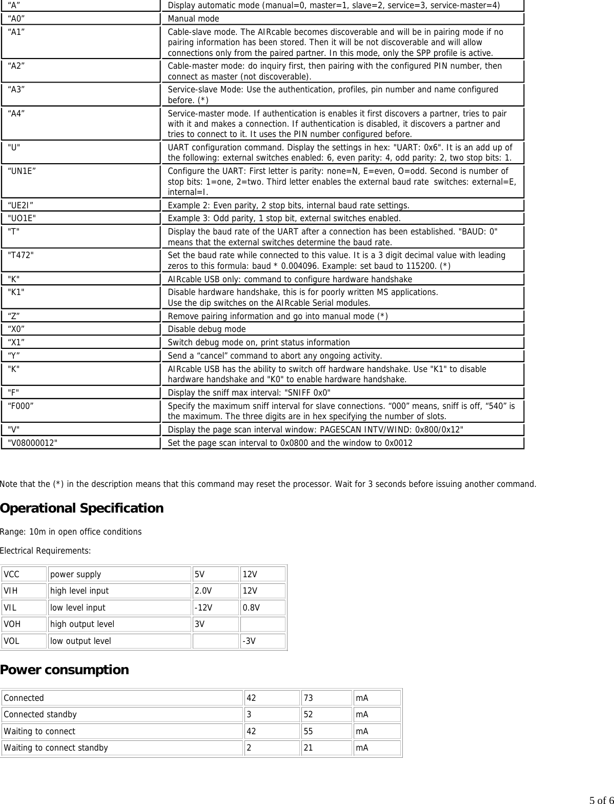
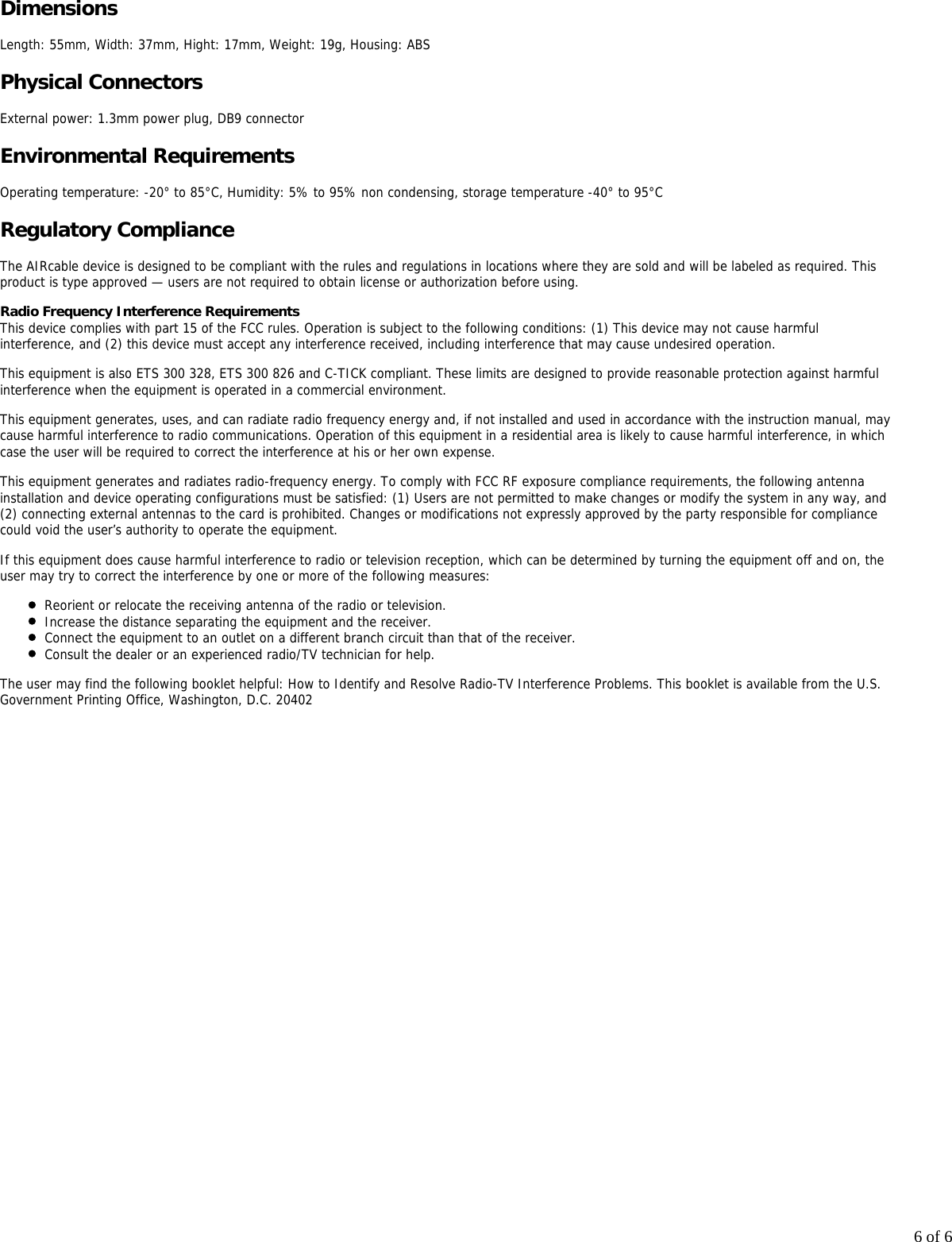
User Manual
2.
user manual update
user manual update
Navigation menu
Upload a User Manual
Namespaces
Wiki Guide
HTML
PDF
Info
Views
User Manual
Discussion / Help
Navigation