Wireless Matrix MBS2A Mobile base station with L-Band Sat, GSM and WLAN User Manual Style Guide
Wireless Matrix Corporation Mobile base station with L-Band Sat, GSM and WLAN Style Guide
Contents
- 1. Installer Guide
- 2. Users Manual
- 3. Users Guide
Installer Guide

Wireless Matrix Corporation Document Number MBUD-0085v1b
12369-B Sunrise Valley Drive, Reston, VA 20191 Version 1.0b
Phone : (703) 262-0500 March 04, 2004
FAX : (703) 262-0380
www.wirelessmatrixcorp.com
Wireless Matrix
MBS2 Installation Guide

Wireless Matrix MBS2 Installation Guide Document MBUD-0085v1b
MBS2 Installation Guide
Copyright © 2004 Wireless Matrix Corporation. All rights reserved.
Printed in the United States of America
This document is proprietary to Wireless Matrix Corporation. Do not reproduce, use or disclose
without permission.
We have made every effort to ensure the accuracy of all information contained in this document.
However, Wireless Matrix Corporation makes no expressed or implied warranty or representation
based upon the enclosed information.
Revision History:
Version 1.0b 3/04/04 Initial Version
March 04, 2004 Page ii

Wireless Matrix MBS2 Installation Guide Document MBUD-0085v1b
Wireless Matrix MBS2 Installation Guide
TABLE OF CONTENTS
REGULATORY STATEMENTS ....................................................................................................................... IV
OTHER SAFETY PRECAUTIONS .................................................................................................................... V
INTRODUCTION............................................................................................................. 1
TECHNICAL SUPPORT................................................................................................. 1
USER INFORMATION ................................................................................................... 1
PRE-INSTALLATION CONSIDERATIONS ............................................................... 1
GENERAL CONSIDERATIONS........................................................................................................................ 2
PERFORMANCE CONSIDERATIONS ............................................................................................................... 2
SPECIAL MOUNTING RECOMMENDATIONS .................................................................................................. 2
INSTALLATION OVERVIEW ...................................................................................... 3
INSTALLATION ............................................................................................................................................ 3
SYSTEM CONNECTIONS ............................................................................................. 3
INSTALLATION INSTRUCTIONS .............................................................................. 4
ANTENNA INSTALLATION ............................................................................................................................ 4
WIRELESS MATRIX MBS2 INSTALLATION PROCEDURES ............................................................................ 5
WIRELESS MATRIX MBS2 SYSTEM VERIFICATION LIST ............................................................................. 9
POTENTIAL PROBLEMS .............................................................................................................................. 10
WARRANTY................................................................................................................... 11
RETURN POLICY ......................................................................................................... 12
APPENDIX - WIRELESS MATRIX MBS2 COMPONENT LIST........................... 15
March 04, 2004 Page iii
Wireless Matrix MBS2 Installation Guide Document MBUD-0085v1b
Regulatory Statements
Read and understand the entire manual and follow the safety instructions.
The following regulatory approvals apply for the Mobile Base Station 2 (MBS2):
• FCC
• IC
• PTCRB
FCC Part 15 Compliance
This device complies with Part 15 of the FCC Rules. Operation is subject to the following two conditions:
1. This device may not cause harmful interference
2. This device must accept any interference received, including interference that may cause
undesired operation.
Modifications not expressly approved by Wireless Matrix USA, Inc. could void the user's authority to
operate the equipment.
NOTE: This equipment has been tested and found to comply with the limits for a Class B digital
device, pursuant to Part 15 of the FCC Rules. These limits are designed to provide
reasonable protection against harmful interference in a residential installation. This
equipment generates, uses and can radiate radio frequency energy and, if not installed and
used in accordance with the instructions, may cause harmful interference to radio
communications. However, there is no guarantee that interference will not occur in a
particular installation. If this equipment does cause harmful interference to radio or
television reception, which can be determined by turning the equipment off and on, the
user is encouraged to try to correct the interference by one or more of the following
measures:
• Reorient or relocate the receiving antenna.
• Increase the separation between the equipment and receiver.
• Connect the equipment into an outlet on a circuit different from that to which the
receiver is connected.
• Consult the dealer or an experienced radio/TV technician for help.
The MBS2 satellite radio emits radio frequency (RF) energy when transmitting. The MBS2 must be
installed in a manner that provides a minimum separation distance of 20 cm or more between the antenna
and persons to satisfy FCC RF exposure requirements for mobile transmitting devices.
Operators should maintain a safe distance from radio when transmitting. Wireless Matrix recommends
installing the MBS2 device with a safe distance of 51 cm or more. The safe distance of 51 cm is measured
from the center of the antenna beam with respect to the FCC OET Bulletin 65, Edition 97 01 “Evaluating
Compliance With FCC Guidelines for human Exposure to Radiofrequency Electromagnetic Fields”. The
51 cm distance should be maintained under the following conditions:
• The antenna is powered on and transmitting. The MBS2 transmits only when the computer in the
vehicle sends messages to the host computer.
• A person is blocking line-of-sight to the satellite during transmission. A person on or above the
vehicle roof and within 51 cm of the unit could interfere with the MBS2 transmission path.
March 04, 2004 Page iv

Wireless Matrix MBS2 Installation Guide Document MBUD-0085v1b
Other Safety Precautions
Read and understand the complete Installation Guide, including the Safety Precautions, prior to using the
MBS2 Modem.
The MBS2 is a radio unit used to receive and transmit data. When in operation, the MBS2 transmits and
receives RF signals to and from a Geo-stationary orbital satellite.
The MBS2 must be used in accordance with the safety guidelines stated in this document. Failure to
comply could result in physical harm and can be a hazard to the health of the operator of this unit.
WARNING!
The following safety precautions must be observed during all phases of the operation, usage, service or
repair of the MBS2 unit.
1. The MBS2 must be operated at the voltages described in the unit technical documentation.
2. The MBS2 must not be mechanically or electrically changed or modified. Use of all connectors
should follow the guidance of the MBS2 technical documentation.
3. Replace fuse with same type and rating for protection against fire and damage.
4. The MBS2 is a Radio Frequency (RF) generating device. Do not operate the unit when anyone is
in the vicinity noted in the Safety Information section of this guide. This could result in personal
injury.
5. Do NOT operate the MBS2 unit in areas where explosives are in use as the RF frequency could
interfere with the operation, causing hazardous conditions. Do NOT operate the MBS2 unit in
areas where two-way radio communications is prohibited.
6. Use discretion when determining the MBS2 installation point. After installation, ensure that all
systems are functioning properly. Consult vehicle dealer for further information.
WARNING!
1. Replace fuse with same type and rating for protection against fire and damage.
2. The Wireless Matrix MBS2 is a RF generating device. Do not operate the unit when anyone is in
the vicinity noted in the Safety Information section of this guide. This could result in personal
injury.
3. Do NOT operate the MBS2 unit in areas where explosives are in use as the RF frequency could
interfere with the operation, causing hazardous conditions. Do NOT operate the MBS2 unit in
areas where two-way radio communications is prohibited.
4. Use discretion when determining the MBS2 installation point. After installation, ensure that all
systems are functioning properly. Consult vehicle dealer for further information.
CAUTION!
1. READ THIS MANUAL IN ITS ENTIRETY!
2. Keep all original Packing Materials.
3. Use caution when installing screws or drilling through the body of the vehicle to avoid puncturing
critical areas.
4. Install included grommets and weather sealant to protect cable integrity and weatherproofing the
area of penetration.
5. Follow the instruction enumerated in the Installation Section of this guide to ensure proper
hardware installation.
6. Ensure that the MBS2 is installed in an area with sufficient overhead clearance where it will NOT
collide with any other surfaces and in a location that will NOT affect the RF transmission.
March 04, 2004 Page v
Wireless Matrix MBS2 Installation Guide Document MBUD-0085v1b
7. Pay close attention to the electrical power installation requirements described in this guide.
Failure to comply with the described section could result in serious damage to the electrical
system of the vehicle.
.
March 04, 2004 Page vi

Wireless Matrix MBS2 Installation Guide Document MBUD-0085v1b
MBS2 Installation Guide
INTRODUCTION
This guide explains procedures for installing the Wireless Matrix Mobile Base Station 2 (MBS2) modem.
The guide does not provide detailed installation instructions for every type of vehicle. Instead, because of
the variety of available vehicle makes and models, it outlines the installation process and allows the
installer to choose appropriate options.
Though the installation process is straight forward, it is important to plan your installation carefully. By
planning your installation, you can avoid potential problems and determine the best approach to installing
the Wireless Matrix MBS2. Be aware that changes to a component’s position or mounting method may be
necessary because of vehicle differences that we could not anticipate when writing this guide. Try to
predict installation variations by reviewing the Installation Instructions section of this guide before
installing the Wireless Matrix MBS2 hardware.
This guide is broken into three different sets of installation instructions, covering the steps for installation
on the basis of the communications configuration of the MBS2 unit. As there are divergent steps in wiring
and other installation elements associated with each of the configurations, each section will be all-inclusive
for the installation of the configuration identified.
TECHNICAL SUPPORT
Technical support is provided through your service provider. They will provide information and answers to
questions about the hardware and software described in this guide. Please reference your Problem
Escalation Guide for your technical support listing.
USER INFORMATION
The Wireless Matrix MBS2 is a combination of communication hardware that, when connected to the
Client Side Computer (CSC), provides the most sophisticated communication functionality currently
available. The Wireless Matrix MBS2 consists of an antenna and a power-data cable. Before shipping,
Wireless Matrix will configure and commission the Wireless Matrix MBS2 on its Mobile Data Services
network for your account.
PRE-INSTALLATION CONSIDERATIONS
You should perform a pre-installation evaluation before installing any Wireless Matrix MBS2 components.
A pre-installation evaluation will provide information about how and where to install the Wireless Matrix
MBS2 and will help identify potential installation problems. During the pre-installation evaluation, you
should estimate available space for component placement, cable routing and inspect the vehicle’s roof to
determine its suitability for an antenna installation. After completing a pre-installation evaluation, you
should know where to locate components, how to route cabling and what antenna shelf or antenna bracket
type to use for the particular installation.
Contact your vehicle dealer for information about obtaining an Original Equipment Manufacturer (OEM)
antenna shelf or bracket. Wireless Matrix antenna brackets are also available.
March 04, 2004 Page 1
Wireless Matrix MBS2 Installation Guide Document MBUD-0085v1b
General Considerations
• Check for wires or obstructions at the opposite side of any panel in which you intend to drill.
• Stay at least 20 inches away from an operating antenna when you are above the level of the
antenna base.
• Do not remove the antenna cover. Removing the antenna cover will void the product warranty.
• Do not paint the antenna. Paint on the antenna will void the product warranty. Paint may also
interfere with signal transmission or reception.
• Avoid stretching or pinching the power-data cable when tilting the cab of a cab-over vehicle.
Performance Considerations
• The antenna mount must support the antenna weight and wind force created by vehicle motion.
• An “unobstructed line of sight” from the antenna to the satellite is essential for reliable
communications.
• Avoid tight bends and kinks in the power-data cable; the tightest allowable bend radius is 2-
inches.
• Avoid installing equipment in places that may obstruct the driver’s view or restrict access to
vehicle controls.
• Metal air dams, metallic paint or air dams made out of fiberglass with embedded metal may cause
antenna interference and will limit antenna placement options.
Special Mounting Recommendations
• Mount the antenna as far forward as possible and center it between the sides of the vehicle. If
centering the antenna (side to side) is not possible, move it toward the driver’s side to minimize
potential damage by contact with limbs from roadside trees.
• Ensure that the top of the antenna is no higher than the legal 13 1/2-foot limit.
• Secure the power-data cable with cable clamps every 12 to 18-inches and keep it at least 12-inches
from the nearest exhaust stack.
• Ensure that cables will not rub against sharp objects or edges.
• Avoid attaching Wireless Matrix MBS2 components to parts that could pull, strain, or otherwise
cause damage.
• Avoid positioning Wireless Matrix MBS2 components such that accidental damage may occur
during entry or exit of the vehicle.
March 04, 2004 Page 2

Wireless Matrix MBS2 Installation Guide Document MBUD-0085v1b
INSTALLATION OVERVIEW
Installation
Installing the Wireless Matrix MBS2 is not difficult, but you must consider the variables involved, such as,
the truck type and location of existing equipment. Installation time can vary depending upon the installer’s
experience and the vehicle design. While a single individual can perform most installation operations,
certain procedures may require the help of a second person. Wireless Matrix offers an installation training
program, or can recommend installation vendors in your area who can performs the installation.
Some of the following procedures may require a choice between several hardware options. Some options
are not suitable for some installations, so Wireless Matrix recommends that you verify vehicle integrity
with the vehicle OEM to ensure that the vehicle structure can support the Wireless Matrix MBS2
components. Also, verify that you have the parts and tools necessary to complete the installation.
To install the Wireless Matrix MBS2, follow these steps:
1. Select location for mounting the antenna. Assess cable routes while considering antenna
placement.
2. Determine the type of bracket to use, and contact the vehicle OEM for bracket availability.
3. Determine if the proper Wireless Matrix MBS2 installation requires temporary removal of
vehicle components.
4. Install the shelf or bracket.
5. Install the antenna.
6. Install the power-data cable.
7. Secure all cables to rigid mounts with cable restraints.
8. Verify operation of the Wireless Matrix MBS2.
SYSTEM CONNECTIONS
The Wireless Matrix MBS2 connects to the CSC in a variety of ways, depending on configuration. It can
connect by either a DB9 straight through power extension cable or directly to the DB9 connector on the
supplied power-data cable. It can also connect via 802.11b protocol, or via Ethernet connection.
March 04, 2004 Page 3

Wireless Matrix MBS2 Installation Guide Document MBUD-0085v1b
INSTALLATION INSTRUCTIONS
The following instructions explain the processes for installing the antenna, power-data cable and the power
extension cable. The installation process may vary slightly if the vehicle’s design or accessories will not
permit the execution of the steps outlined below.
Antenna Installation
Ensure there is not a height obstruction. Mount the antenna so that it is level. The highest point of any
peripheral metal object must fall below an ascending 15-degree angle that begins at the horizontal and
vertical center of the antenna; see figures 1 and 2. Wireless Matrix recommends placing other antennas,
e.g., CB or cellular, at least 3-feet from the antenna mount.
Figure 1. Maximum Obstruction Height
Figure 2. Typical Antenna Mount Location
March 04, 2004 Page 4
Wireless Matrix MBS2 Installation Guide Document MBUD-0085v1b
Wireless Matrix MBS2 Installation Procedures
The average time for the Wireless Matrix MBS2 installation is about an hour.
1. The Wireless Matrix MBS2 is mounted using 1/4-inch x 20 tpi (threads per inch) bolts
screwed into its base. The threaded portion in the base is a maximum of 1/2-inches deep. To
prevent damage during installation, care should be taken that the thread engagement of the
mounting bolt be 1/2-inch or less.
2. Locate the desired installation location on the vehicle (ideally on an area where the antenna
will be exposed from all angles, as described in Antenna Installation section of this guide).
3. Place a piece of duct tape over the area to drill, for the antenna mount bolts and cable access
(this will prevent the drill bit from sliding and damaging the roof surface).
4. Place the antenna mount’s (refer to the appendix for the Wireless Matrix part number)
mounting bracket on the desired location and mark the four drilling points (use bracket as a
template for bolt locations).
NOTE:
Avoid drilling through wires, mounted fixtures or equipment. Secure the bracket
to vehicle supports or framing.
5. Drill the four 5/16-inch holes for the antenna mount, as marked by the template, and an
additional 1/2-inch hole at a selected location for cable access.
6. Install the antenna mount’s (refer to the appendix for the Wireless Matrix part number)
antenna bracket with its corresponding mounting hardware.
7. Install the Wireless Matrix MBS2 to the antenna mount’s (refer to the appendix for the
Wireless Matrix part number) mounting plate with the three 1/4-inch mounting bolts and
washers.
8. Assemble the antenna mount’s (refer to the appendix for the Wireless Matrix part number)
mounting plate to the mounting bracket and secure with the mounting hardware.
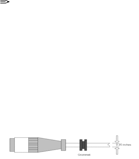
9. Place the 1/2-inch grommet into place (around the cable hole) to protect the cable from
damage.
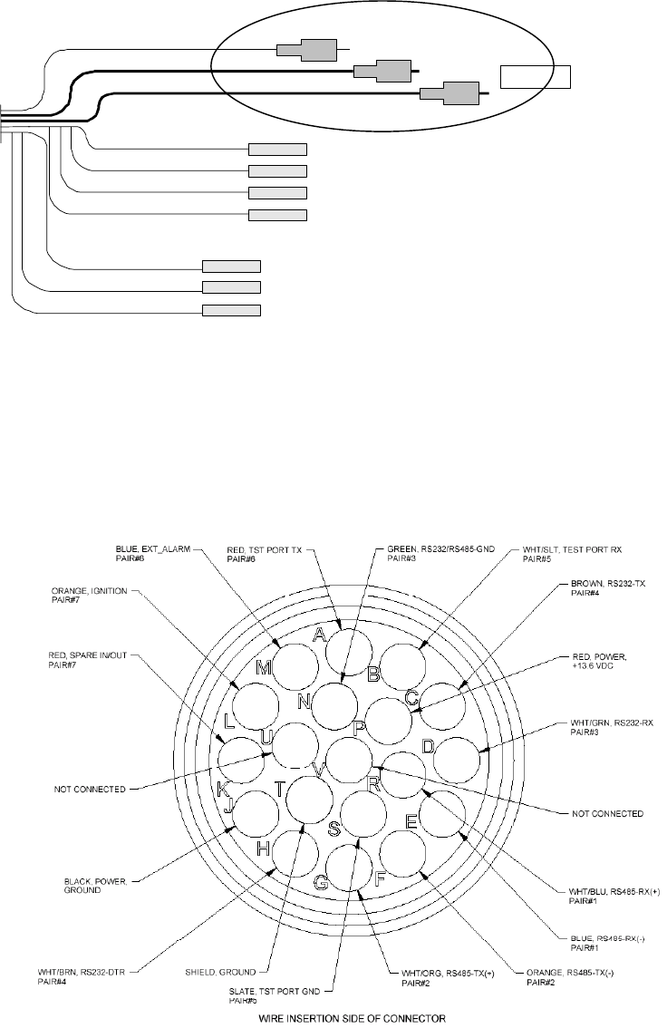
10. The Wireless Matrix MBS2 power-data cable is supplied without the DB9 bodies and shells
installed. Figure 3 displays the wiring diagram for this cable.
Power-Data Cable
March 04, 2004 Page 5
Wireless Matrix MBS2 Installation Guide Document MBUD-0085v1b
#22 Orange
/
/Red
#14 Black
#14 Red
IGN
Gnd +13.6 V
#22 White /Green
#22 Brown
#22 White
/Brown
#22 Green
RXD
TXD
DTR
GND
#22 White
/Slate
#22 Red
/Blue
#22 Slate
/White
OBC Port
contacts to be
inserted in
connector
Female D-sub Crimp
Contacts
PIN #2
PIN #3
PIN #4 OR 7
PIN #5
Test Port
contacts to
be inserted
in connector
PIN #2
PIN #3
PIN #5
RXD
TXD
GND
MBS2 Power-Data Cable (Detail)
Figure 3. Power-Data Cable Configuration Diagram
11. The shells and bodies are supplied separately and are attached to the cable after the unit cable is in
place. This allows the cable to be inserted through a smaller opening in the vehicle chassis.
Figure 4 displays the pinout of the factory-assembled connector that connects to the Wireless
Matrix MBS2.
Figure 4. Wireless Matrix MBS2 Connector Configuration Diagram
March 04, 2004 Page 6
Wireless Matrix MBS2 Installation Guide Document MBUD-0085v1b
NOTE:
The RS-422 transceiver in the MBS2 unit is disabled when the MBS2 is installed
for use in RS-232 mode. As a result, it is acceptable to cut back the unused RS-
422 wires if desired.
Green
4
5
3
2
1
9
8
7
6
Brown
White/Green
White/Brown
Slate/White
4
5
3
2
1
9
8
7
6
Red/Blue
White/Slate
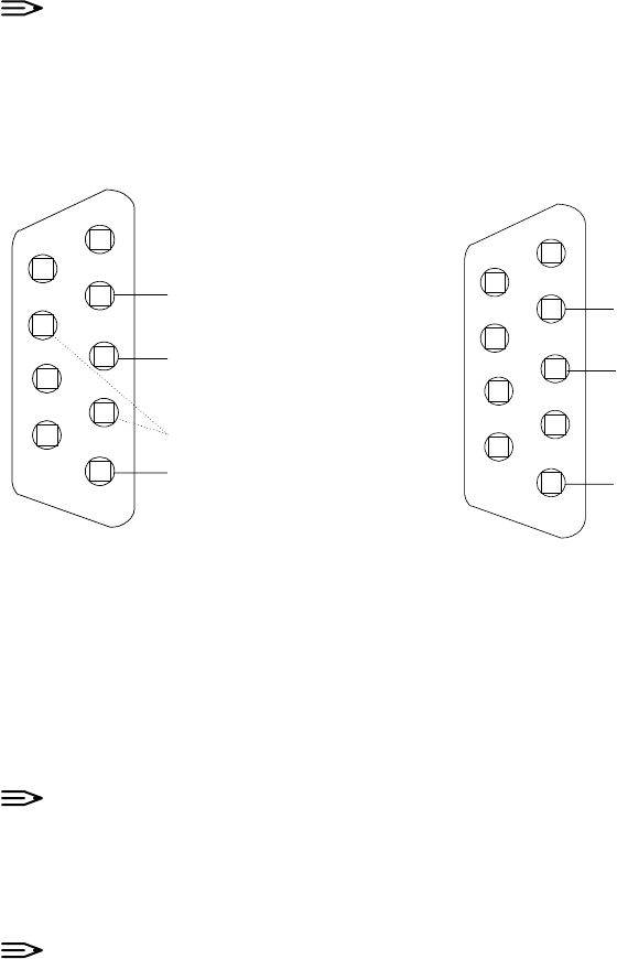
CSC Connector Test Port (Diagnostics) Connector
Figure 5. MBS2 DB9 Connectors
12. See figure 5 for the pin insertion locations. If the DB9 contacts must be removed for any reason,
use Amp tool No. 91285-1 or equivalent.
NOTE:
The DB9 Connector diagram in Figure 5 is looking at the back of the connector.
The backside is considered to be the side with the black plastic protruding and the
two pair twisted cable is to be inserted from this side. The front of the DB9
Connector only has the metal housing protruding.
NOTE:
Some hardware does not support DTR. For this hardware, the white/brown pin
should be routed to Pin 7 (RTS).
13. The CSC connector (see figure 5) is the port used by the Wireless Matrix MBS2 to
communicate with the Client Side Computer (CSC). This port allows the communication
between the Wireless Matrix MBS2 and the CSC to take place.
The CSC is a DB9 Female connector that uses four leads of the power-data cable (19 pin,
cannon connector) with the pin-out configuration as displayed in figure 5.
The Test Port (Diagnostics) connector (see figure 5) is the port used by the Wireless Matrix
MBS2 to communicate with the On Board Computer (OBC) module located within the CSC
for test and diagnostic purposes only. This port allows diagnostics capabilities between the
Wireless Matrix MBS2 and the user interface, such as HyperTerminal.
The Test Port is a DB9 Female connector that uses three leads of the power-data cable (19
pin, Cannon connector) with the pin-out configuration as displayed in figure 5.
March 04, 2004 Page 7
Wireless Matrix MBS2 Installation Guide Document MBUD-0085v1b
14. Run the antenna power-data cable (the end without connectors) from the top of the roof in to
the cabin through the grommet, and route the cable in the inside of the vehicle as desired to
reach the constant 12-volt power source.
15. Connect the power-data cable to the Wireless Matrix MBS2 by matching the connector
grooves and twisting the connector to its locked position.
16. Once the desired length of cable is exposed, use an outside clear silicone sealant to seal and
weatherproof the opening.
17. Select the point of access from the engine compartment into the cabin and drill (if necessary)
a 1/2-inch hole to run the power extension cable into the cabin.
18. From the engine compartment, identify the constant 12-volt power source (a direct lead from
the battery’s positive connector can be used).
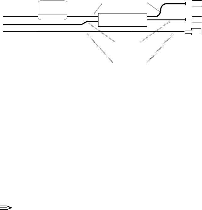
19. Install the fuse lead of the power extension cable (red, 10 to 12 AWG, lead) and connect to
the positive battery lead or selected constant 12-volt power source (see figure 6).
March 04, 2004 Page 8
Wireless Matrix MBS2 Installation Guide Document MBUD-0085v1b
Battery / Ign Cable
To Battery Pos
To Battery Neg
To Ignition
Battery Neg
Black No 10 to 12 AWG
Battery Pos.
Red No 10 to 12 AWG
Ignition
White
No 18 AWG
Recommended Battery/
Ignition Cable
5 Amp
Fuse
Figure 6. Power Extension Cable Installation Diagram
20. Connect the ignition sensor (white, 18 AWG lead) to its corresponding ignition fused
connector at the vehicle’s distribution box using a fuse connector.
21. Select a common grounding point and connect the negative, grounding-wire lead (black, 10 to
12 AWG lead) to its ground (the negative battery lead can be used).
22. Connect the positive (red, 12 AWG lead) and the negative (black, 12 AWG lead) of the power
extension cable to the corresponding positive and negative leads of the power-data cable.
23. Connect the separate ignition extension cable (white, 18 AWG lead) to the corresponding
ignition sensor on the power-data cable (orange/red, 22 AWG lead).
24. Once the power-data cable is installed, assemble the DB9 connectors for the CSC and Test
Ports (use the Cable Configuration Diagram, Figure 5).
NOTE:
A DB9 Male to DB9 Female extension cable may be used from the CSC DB9
connector on the power-data cable to reach the 9-pin serial connector on the CSC.
25. Connect the CSC DB9 connector to the 9-pin serial communications port on the CSC.
26. Follow the steps included in the Wireless Matrix MBS2 System Verification List section of
this guide.
Wireless Matrix MBS2 System Verification List
To verify the Wireless Matrix MBS2 System is operational; follow this checklist:
1. Move the vehicle to an area where there are no obstructions to the southern exposure for the
Wireless Matrix MBS2.
2. Check the cable connections going from the CSC to the Wireless Matrix MBS2 and verify
they are securely connected.
3. Verify the power source output is 11 to 16 volts.
4. Attempt to send a message to the host or have the host send a message to the vehicle.
March 04, 2004 Page 9

Wireless Matrix MBS2 Installation Guide Document MBUD-0085v1b
Potential Problems
The most common problems with the CSC are power connections and configuration. PLEASE consult
your information services department for details in configuring your CSC.
Table 1 lists potential problems with the CSC and suggestions to correct the problems.
Symptom Suggestions
The CSC does not power up. a. Check that the power cable is properly connected
to the antenna and the power source.
b. Using the multi meter, verify power is 11-16 volts
when the vehicle is on.
c. Check the power fuse, and ensure it is connected
properly.
d. Check that the vehicle ignition is on and the
ignition sensor is connected properly.
e. Check that the CSC is powered on.
f. If the problem persists, test the cable for continuity
and/or damage.
Power is on, but the CSC
application will not connect to
the remote host.
a. Check that your CSC is connected to the CSC
DB9 connector, NOT THE TEST PORT.
b. Check that the Wireless Matrix MBS2 cable is
properly connected.
c. Contact your service provider and verify the
following:
i. The correct address is configured in the CSC.
ii. The address in the CSC corresponds
with the X.121 and IP address of the Wireless
. Matrix MBS2 unit. This address is located on a
. label on the Wireless Matrix MBS2.
iii. The Wireless Matrix MBS2 unit is commissioned
and authorized for use.
Table 1. Symptom and Suggestions for Potential Problems
March 04, 2004 Page 10

Wireless Matrix MBS2 Installation Guide Document MBUD-0085v1b
WARRANTY
Wireless Matrix warrants that upon shipment to Customer from supplier’s facility and for the Warranty
Period, hereinafter defined, the Equipment shall be free from defective materials and faulty workmanship
and capable of accessing the Service ("Good Working Order"). The warranty provided herein shall not
apply to (i) hardware normally consumed in operation such as fuses, cables, or mounting brackets, (ii)
defects which, due to no fault of Wireless Matrix, are the result of improper use or maintenance of the
Equipment, (iii) improper operation of the Equipment used with other equipment, (iv) Equipment which,
due to no fault of Wireless Matrix, has been subjected to any kind of detrimental exposure or has been
involved in any accident, fire, explosion, Act of God, or any other cause not attributable to Wireless
Matrix, (v) any Equipment which has been altered or repaired by any party other than Wireless Matrix
without Wireless Matrix’s prior consent, (vi) any Equipment sealed against the weather whereby the seal
has been broken without Wireless Matrix’s prior consent, or (vii) any Equipment hardware or software,
including any revisions provided by Wireless Matrix, which has been improperly stored, installed or
implemented. Customer shall de-install and return (unless otherwise directed by Wireless Matrix) the
failed Equipment to Wireless Matrix. Wireless Matrix shall return the Equipment, or a new or
reconditioned unit, at Wireless Matrix’s option, free of charge to Customer via best way ground, unless
otherwise specified by Customer (with additional costs thereof to Customer’s account), during the one year
from shipment ("Warranty Period"). Wireless Matrix's warranty obligation is limited to restoring the
Equipment to Good Working Order. The repaired or replacement Equipment is warranted for the
remainder of the original Warranty Period.
March 04, 2004 Page 11

Wireless Matrix MBS2 Installation Guide Document MBUD-0085v1b
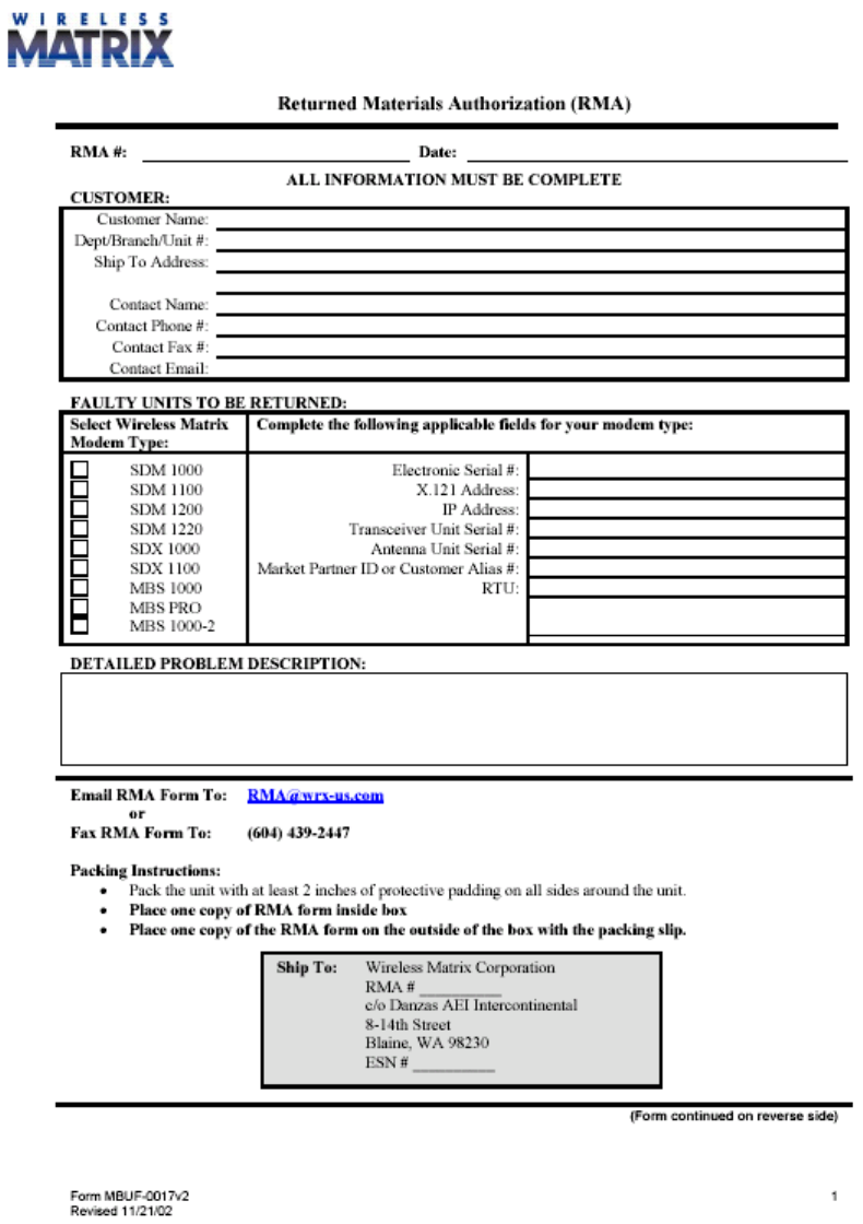
RETURN POLICY
If the troubleshooting process in the Potential Problems section of this guide determines the modem to be
defective, return the unit to Wireless Matrix for repair. Contact your service provider and request a Return
Material Authorization (RMA) number. To receive an RMA number, be prepared to provide:
1. Customer Address
2. Contact Name and Phone Number
3. Serial Number
4. P.O # (If unit is out of Warranty)
5. Brief description of the problem
Please fill out the RMA form included in this manual and send it in the box with the unit. To speed the
handling process, please also mark the RMA number on the shipping label. Please return the unit in its
original packing to avoid damage. Ship the unit to:
Wireless Matrix Corporation
c/o Danzas AEI Intercontinental
8-14th Street
Blaine, WA 98230
ATTN: RMA #___________
March 04, 2004 Page 12
Wireless Matrix MBS2 Installation Guide Document MBUD-0085v1b
March 04, 2004 Page 13

Wireless Matrix MBS2 Installation Guide Document MBUD-0085v1b
RMA form (continued)
RMA Form
BELOW IS FOR COMPLETION BY WIRELESS MATRIX
Dead on Arrival In Warranty Out of Warranty
Replacement Unit(s)
Transceiver Serial # Antenna Serial #
Date Received Failure Type (Category & Code) Date Shipped
Problem Description and Actions Taken (Factory use Only) Date/Tech Initials
(please supply Purchase Order)
March 04, 2004 Page 14

Wireless Matrix MBS2 Installation Guide Document MBUD-0085v1b
March 04, 2004 Page 15
APPENDIX - WIRELESS MATRIX MBS2 COMPONENT LIST
Wireless Matrix MBS2 Component Name Part Number
Wireless Matrix MBS2 Modem
906-xxx-xxxx
or
907-xxx-xxxx
Wireless Matrix MBS2 Cable Assembly Kit 800-120-0048
1/2-inch Grommets
Antenna Mount, Low Profile with 1/4-inch Bolt and Nuts
(Optional equipment)
Regular 03-03-037
Adjustable 03-03-071
Low Profile 03-03-075
This Manual
Required Components
Cordless Drill
Cable Connectors and Butt End Connector
5/16-inch and 1/2-inch Drill Bits
Clear Silicone - Outdoor Sealant
Socket Set
Laptop (CSC)
Recommended Tools & Supplies
RS-232 Pin Tool AMP 91285-1
Wire Stripper
Wire Cutter
Split Loom (Wire Organizer)
DB9/Male to DB9/Female, 4-foot (CSC, DB9 Straight Through
Extension Cable)
Cable Ties (Tie Wraps)
Duct Tape
Multi-Meter (for Power and Continuity Testing)
Crimp Tool