Wireless Seismic 00101 Wireless Remote Unit User Manual
Wireless Seismic, Inc. Wireless Remote Unit Users Manual
Users Manual

Preliminary
RT 1000
Deployment Guide
February 21, 2011
R01
Part Number: 90-0004
When Real-time Matters
Wireless Seism ic, I nc.
361 Cent ennial Parkway, Suit e 230
Louisville, CO 80027
720.242.9916

Preliminary
To order additional copies of t his docum ent , send an em ail t o your sales representat ive
requesting t he following:
Part Num ber: 90- 0004- PDF
Part Num ber: 90- 0004- Paper
© 2010- 2011 Wireless Seism ic, I nc. All rights reserved.
All other brands, com pany nam es, product nam es, t radem ark s or serv ice m arks referenced in t his m at erial are t he
propert y of their r espect ive owners, who m ay or m ay not be affiliated wit h, connect ed t o, or sponsored by Wireless
Seism ic, I nc.
Wireless Seism ic, I nc.'s t radem arks, registered t radem arks or t rade dress m ay not be used in connect ion wit h any
product or ser vice t hat is not t he pr opert y of Wireless Seism ic, I nc., in any m anner t hat is likely t o cause confusion
am ong custom ers, or in any m anner t hat disparages or discr edit s Wireless Seism ic, I nc. The products and ser vices
described in t his m aterial m ay not be available in all r egions.

Preliminary
RT 1000 v1.0 3 Deploym ent Guide R01
© 2010- 2011 Wireless Seism ic, I nc. All r ight s reserved.
Table of Contents
1. Overvie w . . . . . . . . . . . . . . . . . . . . . . . . . . . . . . . . . . . . . . . . . . . . 7
1.1 About this Guide . . . . . . . . . . . . . . . . . . . . . . . . . . . . . . . . . . . . . . . . . . 7
1.2 Who Should Use t his Guide. . . . . . . . . . . . . . . . . . . . . . . . . . . . . . . . . . . 7
1.3 Other Docum ents . . . . . . . . . . . . . . . . . . . . . . . . . . . . . . . . . . . . . . . . 12
1.4 Get t ing Help . . . . . . . . . . . . . . . . . . . . . . . . . . . . . . . . . . . . . . . . . . . . 12
2. Layout . . . . . . . . . . . . . . . . . . . . . . . . . . . . . . . . . . . . . . . . . . . . . . 13
2.1 Overview . . . . . . . . . . . . . . . . . . . . . . . . . . . . . . . . . . . . . . . . . . . . . . 13
2.2 Mobilization . . . . . . . . . . . . . . . . . . . . . . . . . . . . . . . . . . . . . . . . . . . . 13
2.2.1 Prerequisites . . . . . . . . . . . . . . . . . . . . . . . . . . . . . . . . . . . . . . . . 13
2.2.2 Get ting Ready . . . . . . . . . . . . . . . . . . . . . . . . . . . . . . . . . . . . . . . 13
2.2.3 Prepare t he Equipm ent . . . . . . . . . . . . . . . . . . . . . . . . . . . . . . . . . 14
2.3 At t he Site . . . . . . . . . . . . . . . . . . . . . . . . . . . . . . . . . . . . . . . . . . . . . 14
2.3.1 Set Up t he Cent ral Recording System . . . . . . . . . . . . . . . . . . . . . . 15
2.3.2 Lay Out t he Equipm ent . . . . . . . . . . . . . . . . . . . . . . . . . . . . . . . . 15
2.3.2.1 Prerequisites . . . . . . . . . . . . . . . . . . . . . . . . . . . . . . . . . . . . 15
2.3.2.2 Assem ble t he Ground Equipm ent . . . . . . . . . . . . . . . . . . . . . . 15
2.3.2.3 Place t he Ground Equipm ent in the Field . . . . . . . . . . . . . . . . 16
3. Sof t w a r e . . . . . . . . . . . . . . . . . . . . . . . . . . . . . . . . . . . . . . . . . . . . 20
3.1 Overview . . . . . . . . . . . . . . . . . . . . . . . . . . . . . . . . . . . . . . . . . . . . . . 20
3.2 I nst alling t he Soft ware . . . . . . . . . . . . . . . . . . . . . . . . . . . . . . . . . . . . . 20
3.3 Upgrading t he Software . . . . . . . . . . . . . . . . . . . . . . . . . . . . . . . . . . . . 20
3.4 Upgrading t he Firm ware . . . . . . . . . . . . . . . . . . . . . . . . . . . . . . . . . . . . 20
4. Ba ck haul . . . . . . . . . . . . . . . . . . . . . . . . . . . . . . . . . . . . . . . . . . . . 21
4.1 Overview . . . . . . . . . . . . . . . . . . . . . . . . . . . . . . . . . . . . . . . . . . . . . . 21
5. Test ing a nd M aint aining t h e Equipm e n t . . . . . . . . . . . . . . . . . . . . 22
5.1 Overview . . . . . . . . . . . . . . . . . . . . . . . . . . . . . . . . . . . . . . . . . . . . . . 22
5.2 Testing the Layout . . . . . . . . . . . . . . . . . . . . . . . . . . . . . . . . . . . . . . . . 22
5.2.1 Line Tests . . . . . . . . . . . . . . . . . . . . . . . . . . . . . . . . . . . . . . . . . . 22
5.2.2 Source Cont rol Tests . . . . . . . . . . . . . . . . . . . . . . . . . . . . . . . . . . 22
5.2.3 Acquisition Param et er Testing . . . . . . . . . . . . . . . . . . . . . . . . . . . . 22
5.2.4 Built - I n- Self- Test ( BI ST) . . . . . . . . . . . . . . . . . . . . . . . . . . . . . . . 22
5.3 Maint aining the Equipm ent . . . . . . . . . . . . . . . . . . . . . . . . . . . . . . . . . . 23
5.3.1 Unit s . . . . . . . . . . . . . . . . . . . . . . . . . . . . . . . . . . . . . . . . . . . . . 23
5.3.2 Ant ennas . . . . . . . . . . . . . . . . . . . . . . . . . . . . . . . . . . . . . . . . . . 23

Preliminary
4RT 1000 v1.0 Deploym ent Guide R01
© 2010- 2011 Wireless Seism ic, I nc. All r ight s reserved.
Table of Contents
5.3.3 Geophones . . . . . . . . . . . . . . . . . . . . . . . . . . . . . . . . . . . . . . . . . 23
5.3.4 Caut ions . . . . . . . . . . . . . . . . . . . . . . . . . . . . . . . . . . . . . . . . . . . 23
6. Rolling . . . . . . . . . . . . . . . . . . . . . . . . . . . . . . . . . . . . . . . . . . . . . 24
6.1 Rolling the Line . . . . . . . . . . . . . . . . . . . . . . . . . . . . . . . . . . . . . . . . . . 24
6.1.1 Overview . . . . . . . . . . . . . . . . . . . . . . . . . . . . . . . . . . . . . . . . . . . 24
6.1.2 Process . . . . . . . . . . . . . . . . . . . . . . . . . . . . . . . . . . . . . . . . . . . . 25
6.2 Rolling the Stat ion . . . . . . . . . . . . . . . . . . . . . . . . . . . . . . . . . . . . . . . . 25
6.2.1 Overview . . . . . . . . . . . . . . . . . . . . . . . . . . . . . . . . . . . . . . . . . . . 25
6.2.2 Process . . . . . . . . . . . . . . . . . . . . . . . . . . . . . . . . . . . . . . . . . . . . 25
7. D e m obiliza t ion . . . . . . . . . . . . . . . . . . . . . . . . . . . . . . . . . . . . . . . 26
7.1 Overview . . . . . . . . . . . . . . . . . . . . . . . . . . . . . . . . . . . . . . . . . . . . . . . 26
7.2 Undeploy t he Ground Equipm ent . . . . . . . . . . . . . . . . . . . . . . . . . . . . . . 26
7.3 Disassem ble t he Ground Equipm ent . . . . . . . . . . . . . . . . . . . . . . . . . . . . 28
8. Tr ou ble sh oot in g . . . . . . . . . . . . . . . . . . . . . . . . . . . . . . . . . . . . . . 30
8.1 Overview . . . . . . . . . . . . . . . . . . . . . . . . . . . . . . . . . . . . . . . . . . . . . . . 30
9. Legal I nfor m a t ion . . . . . . . . . . . . . . . . . . . . . . . . . . . . . . . . . . . . 31
9.1 FCC Rules and Regulat ions Com pliance . . . . . . . . . . . . . . . . . . . . . . . . . . 31
Glossa r y . . . . . . . . . . . . . . . . . . . . . . . . . . . . . . . . . . . . . . . . . . . . . . 33
I ndex . . . . . . . . . . . . . . . . . . . . . . . . . . . . . . . . . . . . . . . . . . . . . . . . 34

Preliminary
R01 RT 1000 v1.0 Deploym ent Guide 5
© 2010- 2011 Wireless Seism ic, I nc. All rights reserved.
List of Figures
List of Figures
Figure 2–1 WRU .............................................................................................. 15
Figure 2–2 LTU ...............................................................................................15
Figure 2–3 Geophone....................................................................................... 15
Figur e 2–4 I nstalling t he Bat t ery ....................................................................... 16
Figur e 2–5 I nstalling t he Geophone ................................................................... 16
Figur e 2–6 I nstalling t he Ant enna ......................................................................16
Figure 2–7 Power on t he Unit ............................................................................ 17
Figure 2–8 Place t he Unit ................................................................................. 18
Figure 4–1 Backhaul Com ponent s...................................................................... 21
Figure 7–1 Power Off t he Unit ........................................................................... 27
Figure 7–2 Undeployed Unit .............................................................................. 28
Figur e 7–3 I nstalling t he Ant enna ......................................................................29
Figur e 7–4 I nstalling t he Geophone ................................................................... 29
Figur e 7–5 I nstalling t he Bat t ery ....................................................................... 29

Preliminary
6RT 1000 v1.0 Deploym ent Guide R01
© 2010- 2011 Wireless Seism ic, I nc. All r ight s reserved.
List of Tables
List of Tables
Table 1–1 Roles and Responsibilit ies ..................................................................7
Table 2–1 LED I ndicators ................................................................................ 18
Table 9–1 Ant enna Specificat ions..................................................................... 31

Preliminary
RT 1000 v1.0 7 Deploym ent Guide R01
© 2010- 2011 Wireless Seism ic, I nc. All r ight s reserved.
1
Overview
1.1 About this Guide
This docum ent provides inform at ion on how t o deploy the RT 1000 in t he field.
1.2 Who Should Use this Guide
The following t able describes t he t ypical seism ic dat a acquisition users. The
expect ed users of t his docum ent are as follows:
Crew ( Layout / Juggies)
Technician ( LTU)
Tr oubleshoot er
Bosses ( Line Crew)
Ta ble 1 – 1 Role s and Respon sibilit ie s
Role Re sp on sibilit y
Bosses ( Line Crew) Responsibilit ies:
• Superv ise line crew personnel ( j uggies)
• Drive and m aint ain t he t rucks used t o transport
personnel and equipm ent t o and from field operations
• Co- ordinat e crew m em bers boarding and exiting
helicopt ers
• Arrange t he safe and or derly transport of equipm ent.
Report s t o:
• Coor dinat or ( St aging)
N OTE: May occasionally visit the doghouse for clarificat ion
of instructions or updat es on line st atus.

Preliminary
8RT 1000 v1.0 Deploym ent Guide R01
© 2010- 2011 Wireless Seism ic, I nc. All r ight s reserved.
Overview
Who Should Use this Guide
Coordinat or ( Staging Coordinat or
/ Landing Zone ( LZ) Coordinat or)
Responsibilities:
• Journey m anagem ent of all vehicles ( including
helicopt ers) and personnel t o specific point s w it hin t he
prospect
• Know ledge of all personnel in t he prospect ; knows w hen
anyone ent ers or leaves t he prospect, and where t hey
go when t hey are t here
• Ensures t hat ground elect r onics ( bag drops) arrive at
the proper locat ion
• Cont rols inventory and general m aint enance of
equipm ent
• Maint ains constant cont act wit h t he crew and r ecorder
• Oversees t he t esting of fresh equipm ent t o be staged
for t he next layout .
Report s t o:
• TBD
N OTE: This role m ay be split in t wo, one person
coordinating helicopt er operat ions, and t he ot her
coor dinating all line crew operations.
Coordinat or ( Survey) Responsibilities:
• Manages t he survey crews. Survey work t akes place in
advance of t he seism ic crew, som et im es weeks or even
m ont hs ahead of seism ic crew m obilization.
• Att em pts t o flag or stake every point st art ing wit h t he
planned receiver and source coordinat es ( delivered by
the Oil Com pany Geophysicist or Birddog)
• Adj usts flags or stakes when necessary based on
physical accessibilit y ( whether or not a vibrat or or drill
rig can get t o a location) , perm itt ed corridor, and
archeological or wildlife exclusion zones
• Flags all access point s and roads ( in cooperat ion wit h
the St aging Coordinat or)
• Delivers t he actual coordinat es to t he Observer t o be
loaded int o the Cent ral Recording System
• Provides updat es t o t hese coordinat es during the proj ect
if ground condit ions or perm it condit ions change
• Ensures t hat t he Cent ral Recording Syst em is configured
wit h t he correct datum and pr oj ection inform at ion
Report s t o:
• TBD
Crew ( Layout / Juggies) Responsibilities:
• Lay out t he ground electr onics
• Pick up t he ground electronics
Report s t o:
• TBD
Table 1 – 1 Roles a nd Re sponsibilit ie s ( cont .)
Role Re sp on sibilit y

Preliminary
R01 RT 1000 v1.0 Deploym ent Guide 9
© 2010- 2011 Wireless Seism ic, I nc. All rights reserved.
Overview
Who Should Use t his Guide
Crew ( Source) Responsibilities:
• Operat ors drive t he vibrat or t rucks
• Licensed shoot ers set off t he dynam ite
• All crew rem ain in constant voice and dat a
com m unication wit h t he r ecorder during product ion
N OTE: The source on a land seism ic survey is usually eit her
vibroseis or dynam it e. Ot her sour ce t ypes such as
poult er charges, accelerated weight drops, or
shot guns m ay be used as well. One j ob m ay have
m ultiple source t y pes due t o access or perm it
issues, such as steep slopes, m asonry construction,
and so on.
Report s t o:
• TBD
Drillers Responsibilit ies:
• Drill source holes
• May also load charge int o t he hole
Report s t o:
• TBD
Geophysicist ( Oil Com pany) Responsibilities:
• Survey design
• Budget
• Delivery of t he final dat a t o t he Oil Com pany
• Makes final decisions on recording param eters w it h t he
help of the Birddog
• Visits t he field once or twice during the proj ect
• Works closely w it h t he Birddog t o protect t he int erest s
of t he Oil Com pany
N OTE: The Geophysicist likely w orks on eit her an asset
team responsible for oil or gas production in the
field where the seism ic shoot is t aking place, or on a
technical t eam responsible for all t he com pany’s
seism ic activity.
Report s t o:
• TBD
HSE Manager Responsibilities:
• Ensures t he healt h and safet y of every person on t he
prospect
• Ensures t here is m inim al environm ental im pact
• Verifies t hat all environm ent al regulations are followed
• Maint ains any m edical facilities in t he field, such as a
sm all first- r esponse clinic or am bulance
• Visits t he Doghouse infrequent ly
• Helps wit h t he HSE com ponent of t he daily and final
report s
Report s t o:
• TBD
Table 1 – 1 Roles a nd Re sponsibilit ie s ( cont .)
Role Re sp on sibilit y

Preliminary
10 RT 1000 v 1.0 Deploym ent Guide R01
© 2010- 2011 Wireless Seism ic, I nc. All r ight s reserved.
Overview
Who Should Use this Guide
Observer Responsibilit ies:
• Prim ar y operat or of t he Cent ral Recording System
• Works in t he Doghouse full- t im e
• Coor dinat es all field act ivit ies during production
• Monit ors t he st at us of t he ground electronics
• Organizes t roubleshoot ing activit ies
• Perform s daily and m ont hly equipm ent t est s
• Cont rols source activat ion ( vibrat ors, dynam it e, and
others)
• Ensures t he qualit y of t he recorded data
• Docum ent s t he recording operat ions
• Determ ines, wit h t he St aging Manager, which ground
electronics need t o be laid out and picked up in advance
of or following sour ce production
• Rem ains aware of cont ractual obligations and works
wit h t he Crew t o enforce t hem
Report s t o:
• TBD
Obser ver ( Junior / JO) Responsibilities:
• Usually an Observer- in- training, and will take over the
Obser ver ’s role when t he Observer is t aking a break
• May also be t he prim ary user of the voice radios in
coor dinating t he operat ions
• Works in t he Doghouse nearly full- tim e
Report s t o:
• TBD
Observer ( Senior/ SO) Responsibilit ies:
• Supervises overall seism ic operations in t he absence of
the Part y Manager
Report s t o:
• TBD
Office Clerk Responsibilities:
• Maint ains an office in the hot el or cam p
• Coordinat es shipping t o and from the field
• Coordinat es dat a delivery
• Reports on deliveries
• Meets w it h t he Party Manager, Observer, and HSE
m anager at t he end of each shift t o provide det ailed
inform at ion for daily report ing
Report s t o:
• TBD
Table 1 – 1 Roles a nd Re sponsibilit ie s ( cont .)
Role Re sp on sibilit y

Preliminary
R01 RT 1000 v1.0 Deploym ent Guide 11
© 2010- 2011 Wireless Seism ic, I nc. All rights reserved.
Overview
Who Should Use t his Guide
Oil Com pany repr esent ative
( Bir ddog)
Responsibilities:
• Makes independent observat ions and repor t s direct ly t o
the Oil Com pany, act ing as oversight
• Ensures t hat t he cont ract is follow ed and that t he
seism ic crew is always acting in the best int erest of t he
Oil Com pany
• A frequent visitor t o t he doghouse, keeps infor m ed on
all HSE and product ion statistics by ov er - t he- shoulder
observat ion of and conversations wit h t he Observer
• Often walks t he line to ensure t hat geophones are
properly coupled t o t he ground ( plant ed) , and ensur es
that t he Observer is perform ing regular Quality Control
( QC) of noise, leakage and geophone response ( used to
det ect bad plant s).
Report s t o:
• Oil Com pany
N OTE: The Birddog is eit her an em ployee of t he Oil
Com pany or is contract ed directly by t he Oil
Com pany. He is oft en t rained as a Geophysicist , and
has frequently worked as an Observer, surveyor, or
party chief in t he past .
Part y Man ager / Par t y Chief Responsibilities:
• Leads t he seism ic crew; responsible for all operat ions
• Acts as t he pr im ary point of cont act for the Birddog
• Maint ains awareness of all HSE and dat a quality
act ivit ies
• Maint ains focus on m axim izing production and
m inim izing cost s
• A frequent visitor t o t he doghouse, keeps infor m ed on
all HSE and product ion statistics by ov er - t he- shoulder
observat ion of and conversations wit h t he Observer
Report s t o:
• TBD
Technician ( LTU) Responsibilit ies:
• Builds and m aint ains t he backhaul network using a
ruggedized lapt op or t ablet PC r unning t he Hardened Rib
Applicat ion ( HRA) . This applicat ion has som e of the
functionalit y of t he CSS, but stream lined for use as a
troubleshoot ing t ool.
• I n frequent com m unication w it h t he Doghouse
Report s t o:
• TBD
Table 1 – 1 Roles a nd Re sponsibilit ie s ( cont .)
Role Re sp on sibilit y

Preliminary
12 RT 1000 v 1.0 Deploym ent Guide R01
© 2010- 2011 Wireless Seism ic, I nc. All r ight s reserved.
Overview
Other Documents
1.3 Other Documents
All RT 1000 docum ent s are described in t he RT 1000 Docum ent s Guide ( P/ N 90-
000 1) .
1.4 Getting Help
To get help on t he RT 1000 Cent ral Recording Syst em , consult t he online help. You
can find t he help docum ent s by clicking t he help icon in t he user interface, or by
navigat ing to t he follow ing directory:
Direct ory Pat h TBD
To get help on t he RT 1000 deploym ent , consult t his docum ent .
I f you cannot find the answers you need, please contact Wireless Seism ic, I nc.
Technical Support at :
361 Cent ennial Parkway, Suit e 230
Louisville, CO 80027
( 720) 242- 9916
13100 Sout hwest Freeway, Suit e 150
Sugar Land, TX 77478
( 832) 532- 5080
suppor t@wirelessseism ic.com
Technician ( Vibrator) Responsibilities:
• Maint ains t he m echanical and elect ronic health of t he
vibrators
• Visits t he Doghouse at j ob start up t o set up t he source
cont r oller com m unications and param eters
• Ret urns t o t he Doghouse as m aintenance requires
Report s t o:
• TBD
Troubleshoot ers Responsibilit ies:
• Frequent ly visits t he Doghouse t o obt ain a
troubleshoot ing report ( either print ed or a file t hat can
be loaded t o a GPS device) , which cont ains line/ st ation
num bers of failures as well as verbal instructions from
the Observer.
• Correct s ground equipm ent failures
Report s t o:
• Observer
Table 1 – 1 Roles a nd Re sponsibilit ie s ( cont .)
Role Re sp on sibilit y

Preliminary
RT 1000 v1.0 13 Deploym ent Guide R01
© 2010- 2011 Wireless Seism ic, I nc. All r ight s reserved.
2
Layout
2.1 Overview
This chapt er describes how to prepar e ( m obilization) and layout ( install) t he
ground electronics.
2.2 Mobilization
Mobilization is t he physical preparat ion for m oving t o t he seism ic dat a
acquisit ion site.
2.2.1 Prerequisites
I n preparat ion for m obilization, define the following:
Survey
Back haul plan
TBD
2.2.2 Getting Ready
Collect all of t he following:
RT 1000 ground equipm ent :
●WRUs
●LTUs
NOTE
Please refer to Table 9–1 Ant enna Specificat ions, on page 31 for t he list
of support ed ant ennas. Use of accessories ot her t han those specified in
this docum ent is not support ed or warrant ied.
NOTE
The LTU includes t he Base Stat ion Unit ( BSU), t he Power over Ethernet
( PoE) , t he bat tery, t he backhaul, and t he m ast.

Preliminary
14 RT 1000 v 1.0 Deploym ent Guide R01
© 2010- 2011 Wireless Seism ic, I nc. All r ight s reserved.
Layout
At the Site
●Ant ennas
●Geophones
●Bat teries
●Ext ra bat t eries
Non- RT 1000 ground equipm ent :
●Recor din g t r uck :
►Power source ( diesel, benzene or ot her t ype of fueled generator)
►Heating, cooling and ventilat ion system
►Ant enna m asts for voice radio, Dat a t elem etry, source control, and
possibly satellit e phone and/ or int ernet
►Shock- m ount ed rack for PC, displays, ser vers, net work devices, out put
devices, and so on
►Therm al plot t er or equivalent
►Desk, chairs, sm all refrigerat or, and coffeepot
►Com puter, m onit ors, keyboar d, m ice, and so on
►Ext ernal int erfaces for installing and t esting
●Safet y equipm ent ( vests, hard hat s, and so on)
●Sour ce cont rollers
●Any ot her t hird- part y equipm ent
●Any ot her shot- relat ed equipm ent
●Tw o- way radios
2.2.3 Prepare the Equipment
Ensure t hat t he cent ral recording system has t he lat est soft ware available inst alled
( see cross- reference TBD in t he RT 1000 Operators Guide)
Ensure t hat t he ground equipm ent has the lat est firm ware available installed ( see
cross- reference TBD in the RT 1000 Operat ors Guide)
Ensure t hat t he industry standard best pract ices are followed for securing t he
equipm ent for t ransport .
2.3 At the Site
You can prepar e t he cent ral recording system hardware and soft ware while the
ground equipm ent is being placed in t he field.
NOTE
The bat t eries require 8 hours of cont inuous charging in t he bat t ery
charger connect ed t o an AC source; therefore, t he batt ery charger will
be locat ed at t he staging area or in t own.

Preliminary
R01 RT 1000 v1.0 Deploym ent Guide 15
© 2010- 2011 Wireless Seism ic, I nc. All rights reserved.
Layout
At t he Site
2.3.1 Set Up the Central Recording System
Set up t he com put er and peripheral equipm ent in t he cent ral recording system
truck or t railer.
2.3.2 Lay Out the Equipment
You can lay out t he ground equipm ent while the cent ral recording syst em
hardware and software is being prepared.
The WRU is shown in t he following figure:
The LTU is show n in the following figure:
An exam ple geophone is shown in t he following figure
2.3.2.1 Prerequisites
You can at tach t he bat teries, ant ennas, and geophones t o t he ground equipm ent
prior t o going int o to t he field, or as you place each unit. I f you are assem bling as
you place t he unit s, ensure t hat you have sufficient quant it ies for each unit , plus a
few spares.
The RT 1000 shall be used wit h only t he supplied ant ennas ( Table 9–1 Ant enna
Specifications, on page 31) at tached t o t he WRU wit h an int egrat ed t ype N m ale
connect or.
The RT 1000 ant ennas shall be installed and handled by professionals
specifically designated for t his purpose.
Changes or m odifications not expressly approved by Wireless Seism ic, I nc. can
void t he users’s aut horit y t o operat e t he equipm ent .
2.3.2.2 Assemble the Ground Equipment
This sect ion describes t he process t o assem ble the ground equipm ent prior t o
deploym ent .
I llustrat ion TBD
Figure 2 – 1 W RU
I llustrat ion TBD
Figure 2 – 2 LTU
I llustrat ion TBD
Figure 2 – 3 Ge ophone
WARNING
I n order t o com ply w it h FCC radio frequency ( RF) exposure
requirem ent s, t he RT 1000 unit s m ust be installed so t hat a m inim um
separation dist ance of 20 cm is m aint ained bet w een t he antenna( s) and
all persons at all t im es during norm al operat ion.

Preliminary
16 RT 1000 v 1.0 Deploym ent Guide R01
© 2010- 2011 Wireless Seism ic, I nc. All r ight s reserved.
Layout
At the Site
To a sse m ble t he ground equ ipm ent :
1Gather t he equipm ent :
●WRU or LTU
●Ant enna
●Geophone
●Bat teries
2At t ach one or m ore bat teries t o t he unit .
●St eps TBD.
3At t ach t he geophone t o t he unit .
●St eps TBD.
4At t ach t he ant enna t o t he unit .
●St eps TBD.
2.3.2.3 Place the Ground Equipment in the Field
This sect ion describes t he process t o ready t he ground equipm ent for int eract ion
with t he cent ral recording syst em ( deploym ent ).
To deploy t he gr ou n d e quipm e n t :
1Prerequisites:
●The WRU or LTU is assem bled wit h batt ery, geophone, and antenna
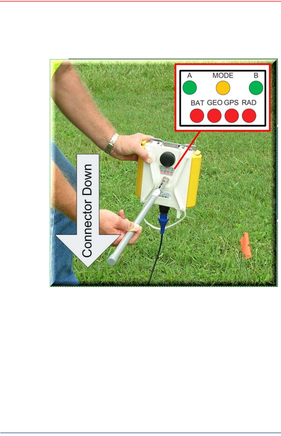
2Pick up t he unit and point the geophone connect or end t owards t he ground as
shown in t he following figure. All of t he LEDs illum inat e:
I m age showing batt ery installat ion TBD.
Figure 2 – 4 I nst a lling t he Ba t t er y
I m age showing geophone installat ion TBD.
Figure 2 – 5 I nst alling t he Geophone
I m age showing ant enna installat ion TBD.
Figure 2 – 6 I nst a lling t he Ant enna
Preliminary
R01 RT 1000 v1.0 Deploym ent Guide 17
© 2010- 2011 Wireless Seism ic, I nc. All rights reserved.
Layout
At t he Site
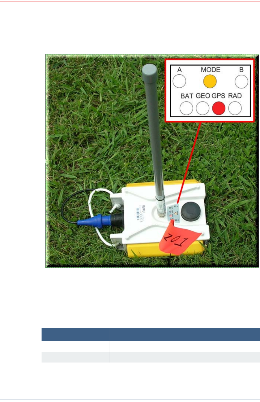
3Place t he unit flat on t he ground as shown in t he following figur e:
Figure 2 – 7 Pow er on t he Unit
Preliminary
18 RT 1000 v 1.0 Deploym ent Guide R01
© 2010- 2011 Wireless Seism ic, I nc. All r ight s reserved.
Layout
At the Site
4The unit will begin a series of int ernal and external t est s. The LEDs on the t op
of the unit indicate t he current t est and whether t he unit passes or fails each
test. The following t able describes when user act ion is required.
Figure 2 – 8 Pla ce t he Unit
Ta ble 2 – 1 LED I ndicat or s
LED St a t e D escrip t ion
Flashing A t est is in progress. No user action required.
Solid green The t est is com plete. No user act ion for green LED.

Preliminary
R01 RT 1000 v1.0 Deploym ent Guide 19
© 2010- 2011 Wireless Seism ic, I nc. All rights reserved.
Layout
At t he Site
Solid red The t est failed as indicated below:
• A or B LED plus red BAT — bat t ery deplet ed
• MODE plus red GEO — geophone not wit hin lim it s
• MODE plus red GPS — GPS fix within 10 m w it hin 1
m in not found
• MODE plus r ed RAD — no neighbor found
Ta ble 2 – 1 LED I ndicat or s
LED St a t e D escrip t ion

Preliminary
RT 1000 v1.0 20 Deploym ent Guide R01
© 2010- 2011 Wireless Seism ic, I nc. All r ight s reserved.
3
Software
3.1 Overview
For t his release, your com put er hardware and ground elect ronics com es wit h
all soft ware installed.
3.2 Installing the Software
TBD
3.3 Upgrading the Software
TBD
3.4 Upgrading the Firmware
TBD

Preliminary
RT 1000 v1.0 21 Deploym ent Guide R01
© 2010- 2011 Wireless Seism ic, I nc. All r ight s reserved.
4
Backhaul
4.1 Overview
TBD
The following figure shows the backhaul com ponent s:
TBD
TBD
Figure 4 – 1 Ba ckhaul Com pon e nt s

Preliminary
RT 1000 v1.0 22 Deploym ent Guide R01
© 2010- 2011 Wireless Seism ic, I nc. All r ight s reserved.
5
Testing and Maintaining the
Equipment
5.1 Overview
This chapt er describes int ernal and ext ernal t ests for t he ground equipm ent .
5.2 Testing the Layout
TBD
5.2.1 Line Tests
TBD
5.2.2 Source Control Tests
TBD
5.2.3 Acquisition Parameter Testing
TBD
5.2.4 Built-In-Self-Test (BIST)
TBD
WARNING
I n order t o com ply w it h FCC radio frequency ( RF) exposure
requirem ent s, t he RT 1000 unit s m ust be installed so t hat a m inim um
separation dist ance of 20 cm is m aint ained bet w een t he antenna( s) and
all persons at all t im es during norm al operat ion.

Preliminary
R01 RT 1000 v1.0 Deploym ent Guide 23
© 2010- 2011 Wireless Seism ic, I nc. All rights reserved.
Testing and Maintaining the Equipment
Maint aining t he Equipm ent
5.3 Maintaining the Equipment
TBD
5.3.1 Units
TBD
5.3.2 Antennas
TBD
5.3.3 Geophones
TBD
5.3.4 Cautions
TBD

Preliminary
RT 1000 v1.0 24 Deploym ent Guide R01
© 2010- 2011 Wireless Seism ic, I nc. All r ight s reserved.
6
Rolling
You can roll the line or roll t he stat ions.
6.1 Rolling the Line
6.1.1 Overview
This chapt er describes how t o m ove t he ground equipm ent across t he survey
area when rolling t he line.
Rolling a line segm ent in your seism ic dat a acquisit ion proj ect m eans t hat you
can set up part of t he equipm ent and then start firing shot s and gat hering
dat a. Once shoot ing is com plete for a specified line segm ent , you can pick up
the equipm ent and m ove it t o a new location while shoot ing cont inues on a
different line segm ent .
You should follow best practices as r ecom m ended by your com pany or t he
industry; however, t he following should be considered when planning your roll
procedures:
Pickup and layout crews pick up lines behind production and lay t hem out
ahead of production. Depending on bat t ery charge stat e, equipm ent m ay
circulat e t hrough staging or go direct ly from one line t o the next .
I n order t o m ake m ost efficient use of layout crews, it is com m on t o lay out
ent ire receiver lines at a t im e even if t hey are longer t han t he t em plat e.
This way crews don’t need t o spend t im e walking or driving from one line
to t he next picking up or laying out sm all am ount s of equipm ent . However,
if the size of t he survey is large and receivers per line m ult iplied by t he
num ber of lines is larger t han t he num ber of channels available, it m ay be
necessary t o roll in the inline direct ion. I n t his case, it is necessary t o be
able t o pick up and lay out WRUs in quantit ies sm aller t han a rib; for
exam ple increm ent s of six WRUs.
During inline roll operat ions, it m ay be desirable t o add newly deployed
WRUs t o an existing ( discovered) rib. The Observer can instruct t he last
WRU in a rib t o poll for neighbors during recording. Newly added WRUs can
begin recording im m ediat ely.

Preliminary
R01 RT 1000 v1.0 Deploym ent Guide 25
© 2010- 2011 Wireless Seism ic, I nc. All rights reserved.
Rolling
Rolling the St at ion
6.1.2 Process
This sect ion describes how t o m ove the equipm ent fr om one location t o anot her.
To r oll t he e quipm ent :
1Follow the instructions in “ Undeploy the Ground Equipm ent ” on page 26 t o
undeploy ground equipm ent .
2Move t he equipm ent t o t he new location, being sure t o secure it firm ly in t he
transport vehicle and perfor m any desired m aintenance ( such as r eplacing
deplet ed bat t eries).
3Follow the instructions in “ Lay Out t he Equipm ent ” on page 15 t o redeploy t he
equipm ent.
6.2 Rolling the Station
TBD
6.2.1 Overview
TBD
6.2.2 Process
TBD

Preliminary
RT 1000 v1.0 26 Deploym ent Guide R01
© 2010- 2011 Wireless Seism ic, I nc. All r ight s reserved.
7
Demobilization
7.1 Overview
This chapt er describes how to prepare ( undeploy) the ground elect ronics for
transport at t he end of a proj ect ( dem obilization) .
7.2 Undeploy the Ground Equipment
This sect ion describes t he process t o ready t he ground equipm ent for
m ovem ent t o a new physical locat ion or t o rem ove it in preparation for
dem obilizat ion.
To u ndeploy t h e ground e quipm e n t :
1Prerequisites:
●The WRU or LTU is assem bled wit h batt ery, geophone, and antenna
●The WRU or LTU is in an active, t ransit ional, or ready st at e
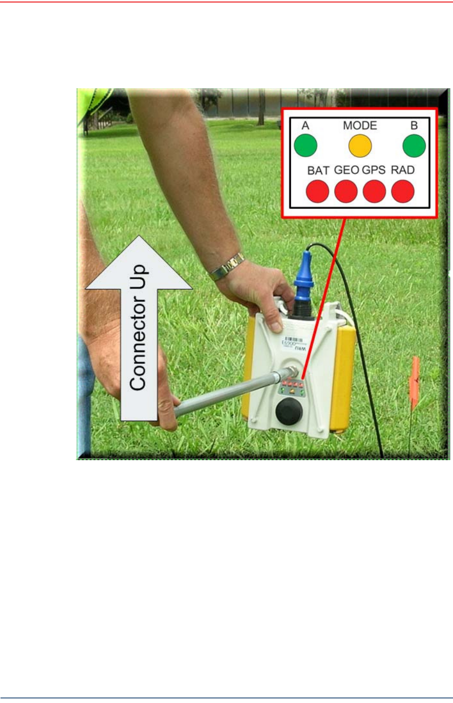
2Pick up t he unit and point the geophone connect or end t owards t he sky as
shown in t he following figure. All of t he LEDs illum inate:
Preliminary
R01 RT 1000 v1.0 Deploym ent Guide 27
© 2010- 2011 Wireless Seism ic, I nc. All rights reserved.
Demobilization
Undeploy t he Ground Equipm ent
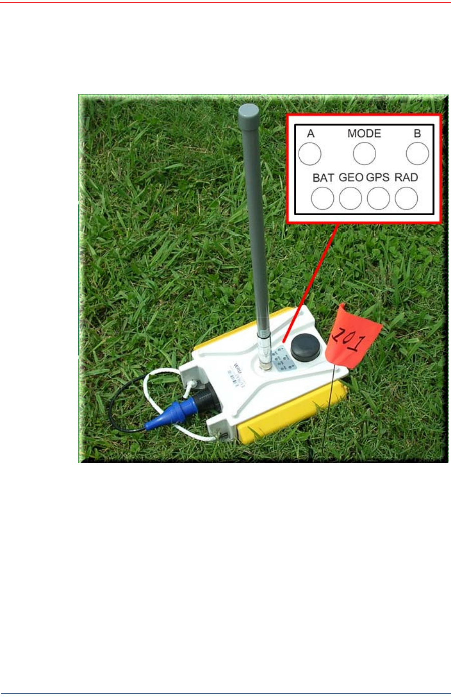
3Place t he unit flat in t he t ranspor t ation vehicle. on t he ground as shown in t he
following figur e. The unit shut s down. The LEDs on t he t op of the unit are off:
Figure 7 – 1 Pow e r Off t he Unit
Preliminary
28 RT 1000 v 1.0 Deploym ent Guide R01
© 2010- 2011 Wireless Seism ic, I nc. All r ight s reserved.
Demobilization
Disassemble the Ground Equipment
4Optional: Rem ove bat teries, ant enna, or geophone as described in
“ Disassem ble t he Ground Equipm ent ” on page 28.
7.3 Disassemble the Ground Equipment
This sect ion describes t he process t o disassem ble t he ground equipm ent prior t o
dem obilizat ion.
To disa sse m ble t he gr ound e quipm ent :
1Undeploy t he equipm ent as described in “ Undeploy t he Ground Equipm ent” on
page 26.
Figur e 7 – 2 Undeployed Unit

Preliminary
R01 RT 1000 v1.0 Deploym ent Guide 29
© 2010- 2011 Wireless Seism ic, I nc. All rights reserved.
Demobilization
Disassem ble t he Ground Equipm ent
2Rem ove t he ant enna from t he unit .
●St eps TBD.
3Rem ove t he geophone from t he unit .
●St eps TBD.
4Rem ove one or m ore bat teries from the unit.
●St eps TBD.
5Secure t he equipm ent in t he transport vehicle.
I m age showing antenna inst allat ion TBD.
Figure 7 – 3 I nst a lling t he Ant enna
I m age showing geophone installat ion TBD.
Figure 7 – 4 I nst a lling t he Geophone
I m age showing bat tery inst allat ion TBD.
Figure 7 – 5 I nst a lling t he Ba t t er y

Preliminary
RT 1000 v1.0 30 Deploym ent Guide R01
© 2010- 2011 Wireless Seism ic, I nc. All r ight s reserved.
8
Troubleshooting
8.1 Overview
TBD

Preliminary
RT 1000 v1.0 31 Deploym ent Guide R01
© 2010- 2011 Wireless Seism ic, I nc. All r ight s reserved.
9
Legal Information
9.1 FCC Rules and Regulations Compliance
The Federal Com m unications Com m ission ( FCC) regulat es t he use of antennas
in t he “ Code of Federal Regulat ions – Title 47, Part 15 – Radio Frequency
Devices, Subpart C – I nt entional Radiat ors, Section 15.203 Ant enna
Requirem ent .”
When used as int ended, t he RT 1000 com plies wit h FCC Section 15.203
requirem ent s as follows:
The RT 1000 ant ennas shall be installed and handled by professionals
specifically designated for t his purpose.
Changes or m odifications not expressly approved by Wireless Seism ic, I nc.
can void t he users’s aut horit y t o operat e t he equipm ent.
The RT 1000 shall be used wit h only t he supplied ant ennas (Table 9–1)
att ached t o t he WRU w it h an int egrat ed t ype N m ale connect or.
NOTE
This equipm ent has been t ested and found t o com ply wit h the lim it s for
a Class A digit al device, pursuant t o part 15 of t he FCC Rules. These
lim it s are designed t o provide reasonable prot ect ion against harm ful
int erference when t he equipm ent is operat ed in a com m ercial
environm ent . This equipm ent generat es, uses, and can radiat e radio
frequency energy and, if not installed and used in accordance w it h t he
instruction m anual, m ay cause harm ful int erference t o radio
com m unications. Operat ion of t his equipm ent in a resident ial area is
likely t o cause harm ful int erference in which case t he user will be
required t o correct t he interference at his own expense.
Table 9 – 1 Ant e nn a Specificat ions
Mode l Fr e que ncy
( MH z) Gain V e r t ical
Ban dw idt h W eigh t
Dim ension
( Le n gt h x
D ia m e t e r )
WSI 65- 0023 2400- 2485 5 dBi 25º 0.5 lbs
0.2 kg
12 x 0.6 in
355 x 15 m m
WSI 6060- 001- 01 240 0- 2485 7 dBi 18° 0.6 lbs
0.3 kg
21 x 0.6 in
540 x 15 m m

Preliminary
32 RT 1000 v 1.0 Deploym ent Guide R01
© 2010- 2011 Wireless Seism ic, I nc. All r ight s reserved.
Legal Information
FCC Rules and Regulations Compliance
WSI 65- 0025 2400- 2485 2 dBi @ 2.4 120° 1.6 oz
45.4 g
7.6 x 0.5 in
193 x 12.7 m m
Ta ble 9 – 1 An t e n n a Specifica t ions ( cont .)
Mode l Fr e que ncy
( MH z) Gain V e r t ical
Ban dw idt h W eigh t
Dim ension
( Le n gt h x
D ia m e t e r )
WARNING
I n order t o com ply w it h FCC radio frequency ( RF) exposure
requirem ent s, t he RT 1000 unit s m ust be installed so t hat a m inim um
separation dist ance of 20 cm is m aint ained bet w een t he antenna( s) and
all persons at all t im es during norm al operat ion.

Preliminary
RT 1000 v1.0 33 Deploym ent Guide R01
© 2010- 2011 Wireless Seism ic, I nc. All r ight s reserved.
Glossary
TBD

Preliminary
RT 1000 v1.0 34 Deploym ent Guide R01
© 2010- 2011 Wireless Seism ic, I nc. All r ight s reserved.
Index
A
an t e nna
specificat ions 31
an t e nna s 31
B
bir ddog 11
bosses
line crew 7
C
con t a ct 12
coor din a t or
landing zone 8
st aging 8
survey 8
cre w
j ug gies 8
layout 7, 8
source 9
D
docum e n t s 12
driller s 9
F
FCC 31
Sect ion 15.203 31
G
geoph ysicist
oil com pany 9
H
he lp 12
HSE
m anager 9
J
JO 10
j ug gie s 7
L
LZ Coor dina t or 8
M
m o dif ica t ion s 31
O
observer 10
j un ior 10
senior 10
office cle r k 10
oil Com pa n y repr esentat ive 11
P
pa r t y
chief 11
m anager 11
S
SO 10
spe cif ica t io ns
ant enna 31
sup por t e d
ant ennas 31
T
t e ch nicia n
LTU 7, 11
vibrator 12
t r ou ble shoo te r 7
t r ou ble shoo te r s 12
U
user s 7

Preliminary
Index
U
35 RT 1000 v 1.0 Deploym ent Guide R01
© 2010- 2011 Wireless Seism ic, I nc. All r ight s reserved.