Wireless Seismic 00105 Wireless Remote Unit User Manual DeploymentGuide
Wireless Seismic, Inc. Wireless Remote Unit DeploymentGuide
UserManual.wiki
>
Wireless Seismic
>
00105 User Manual
Users Manual
Navigation menu
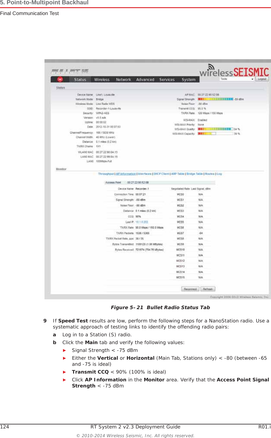
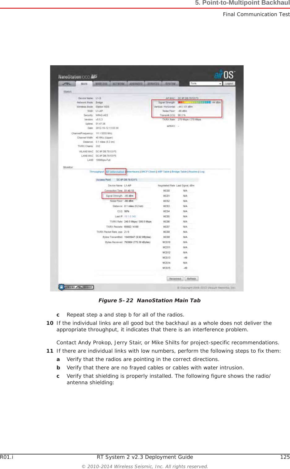
Upload a User Manual
Namespaces
Wiki Guide
HTML
PDF
Info
Views
User Manual
Discussion / Help
Navigation
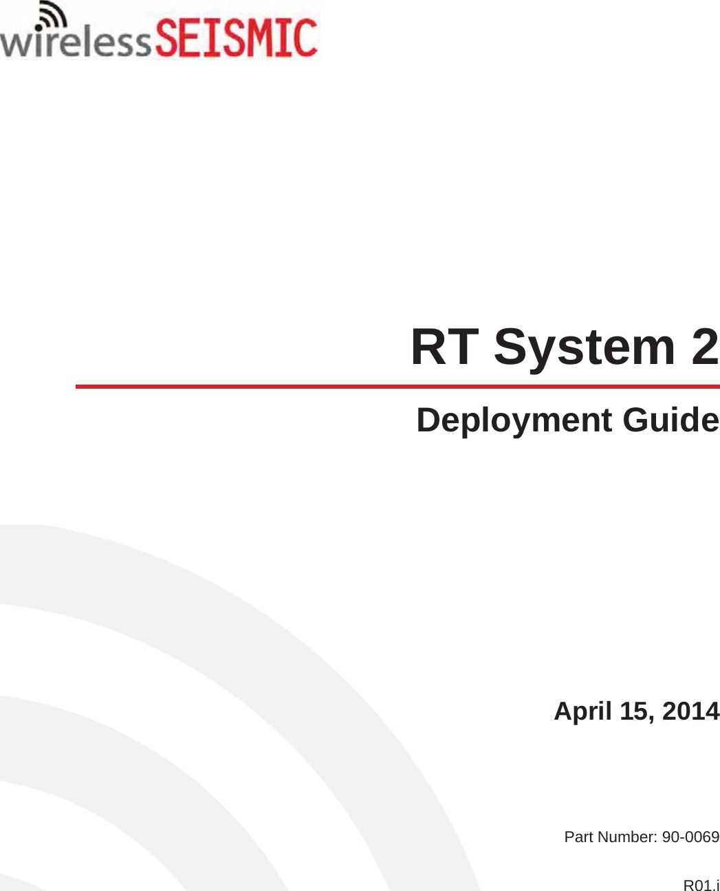

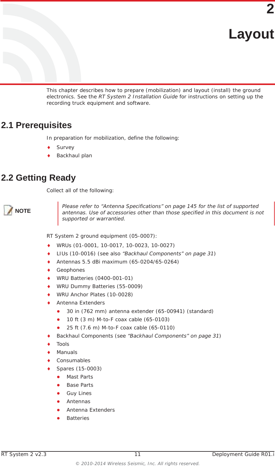
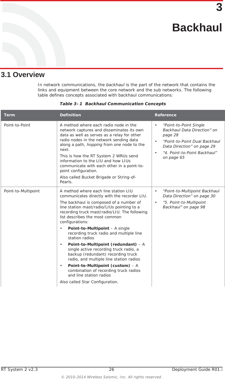
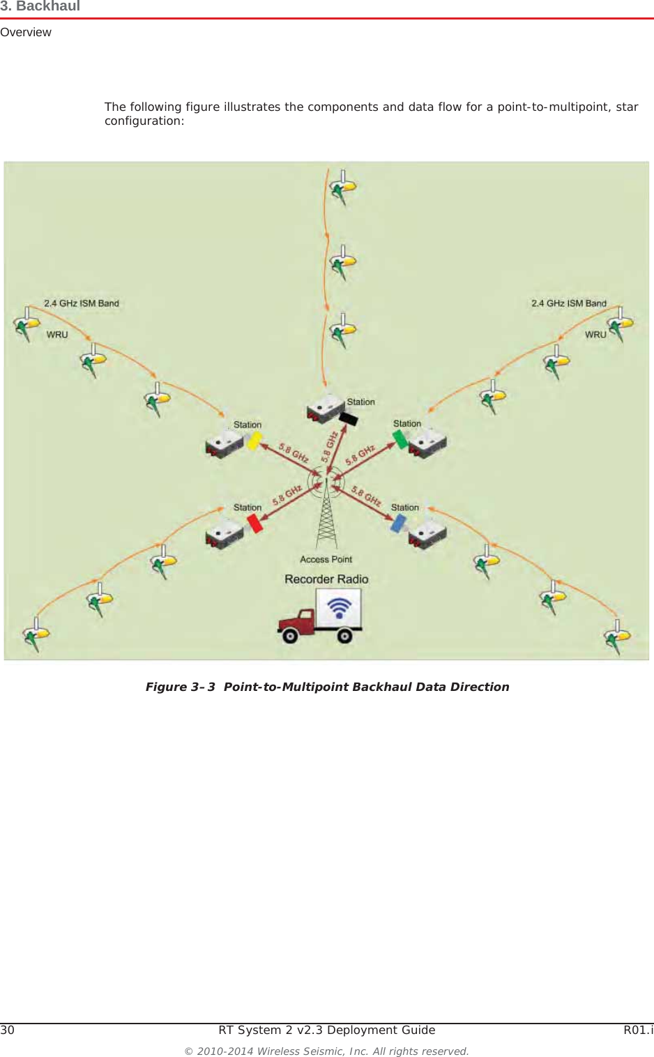
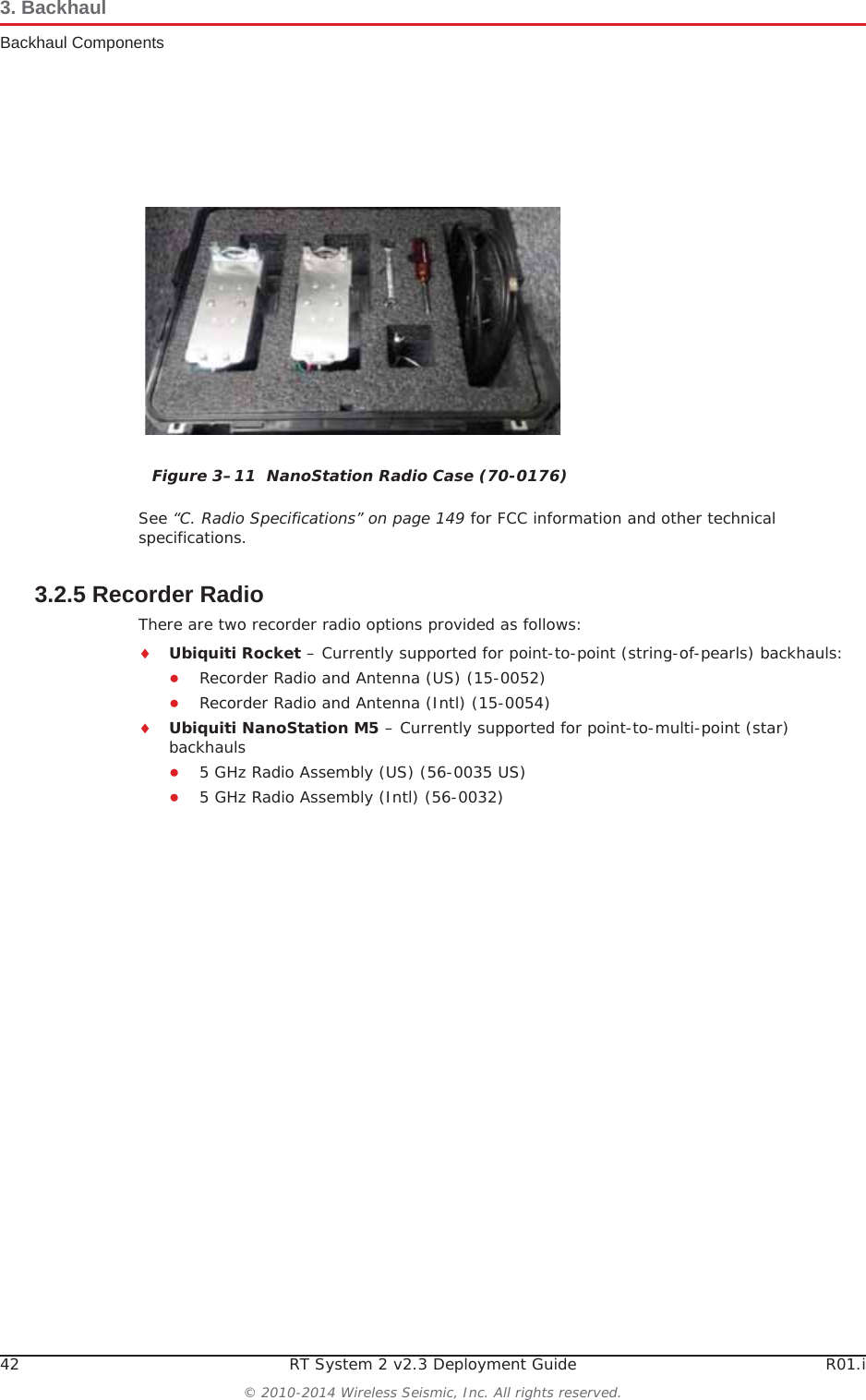
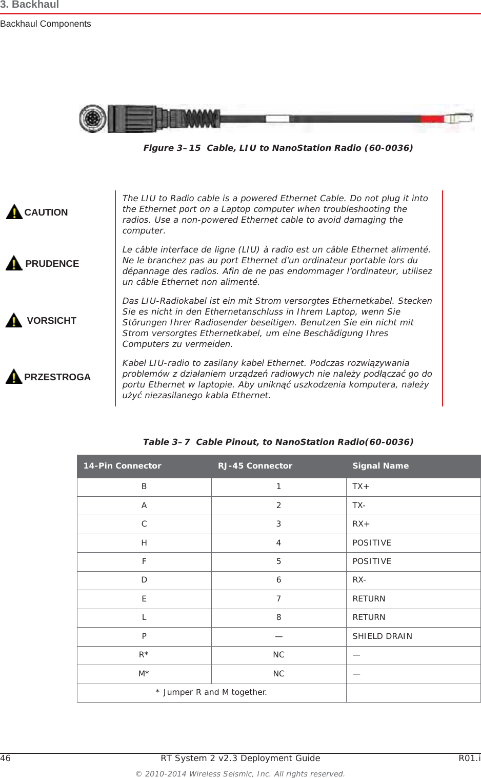
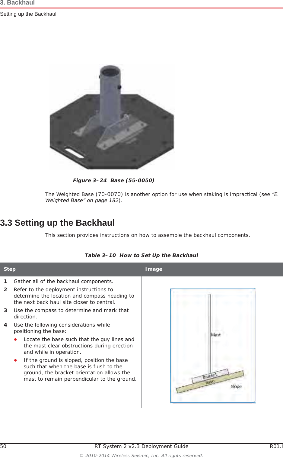
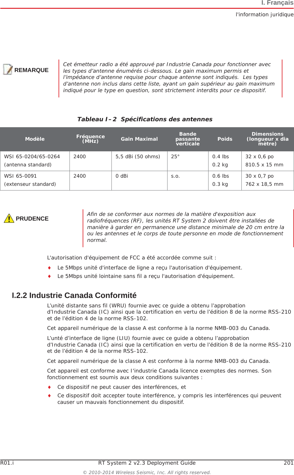
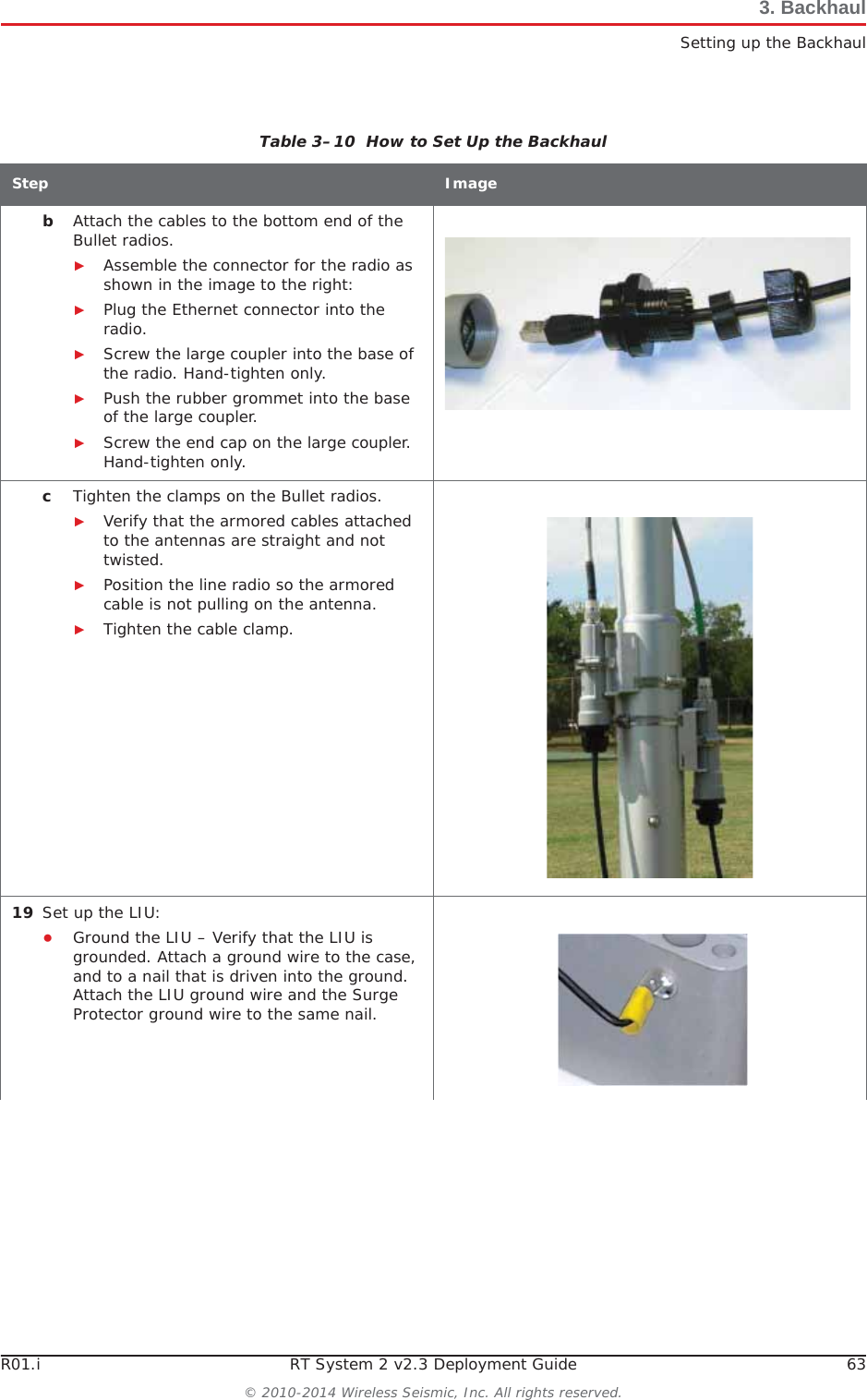
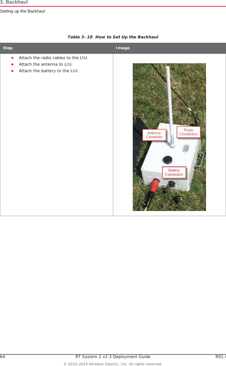
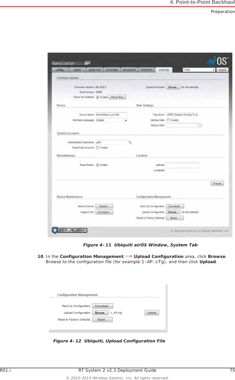
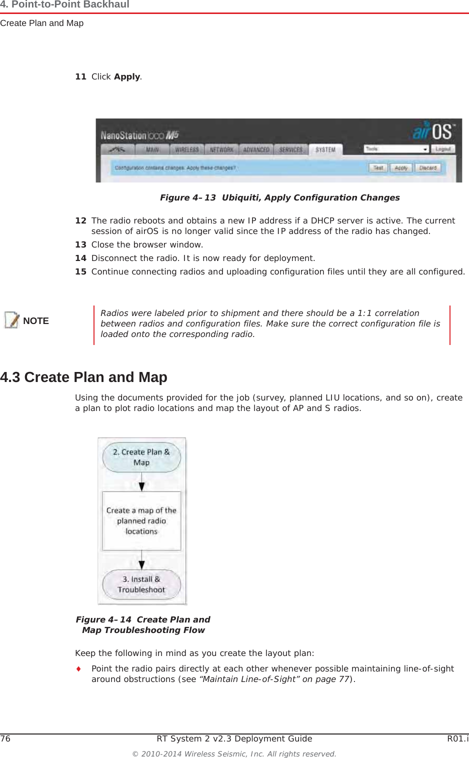
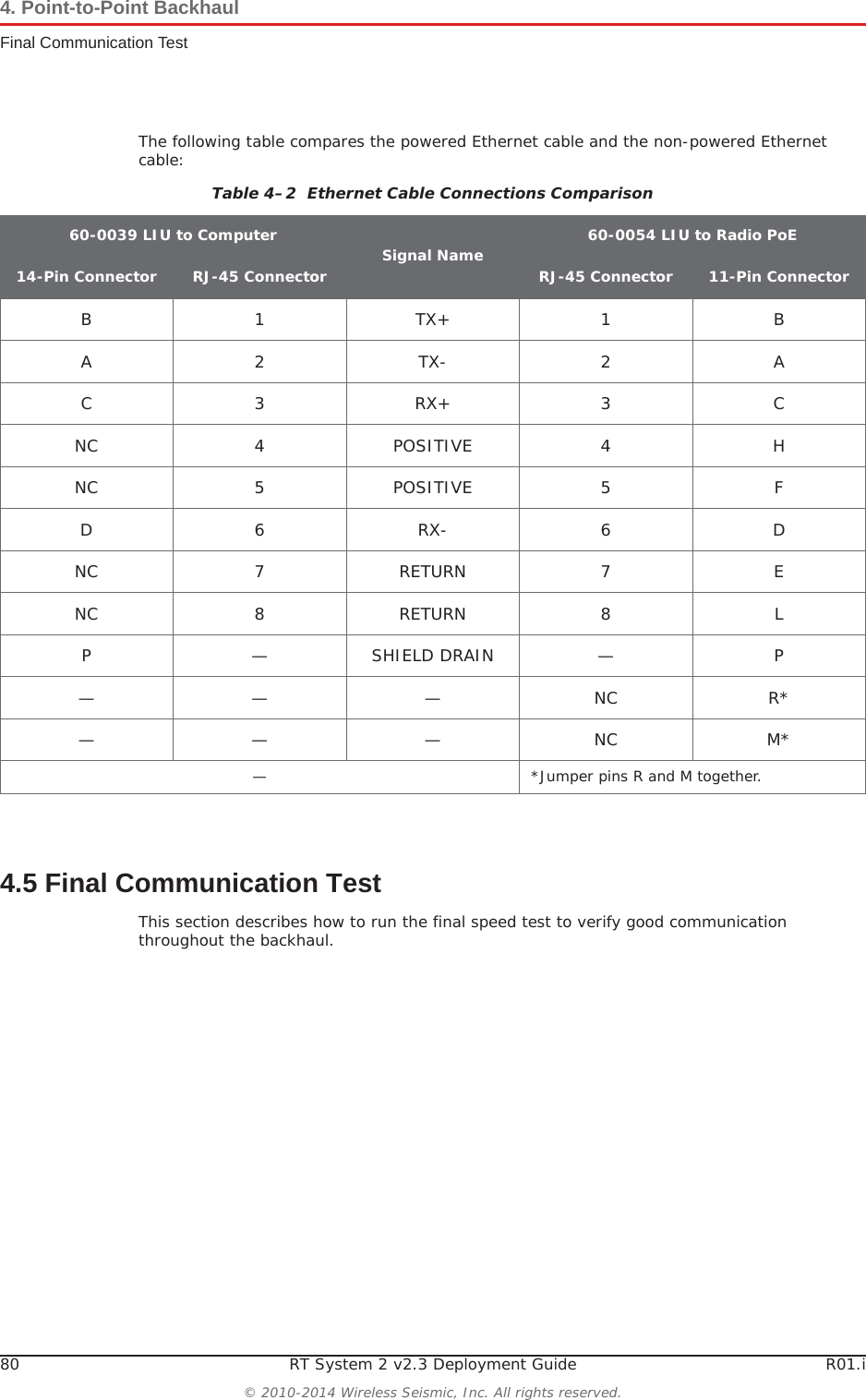
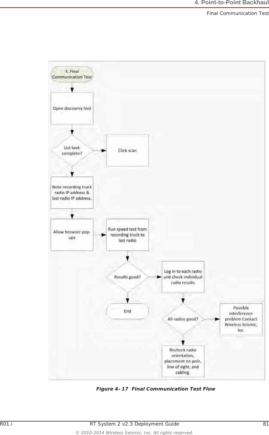
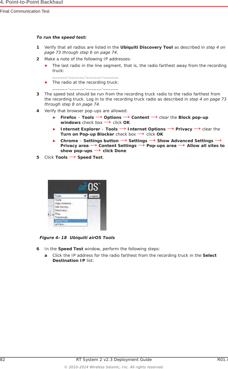
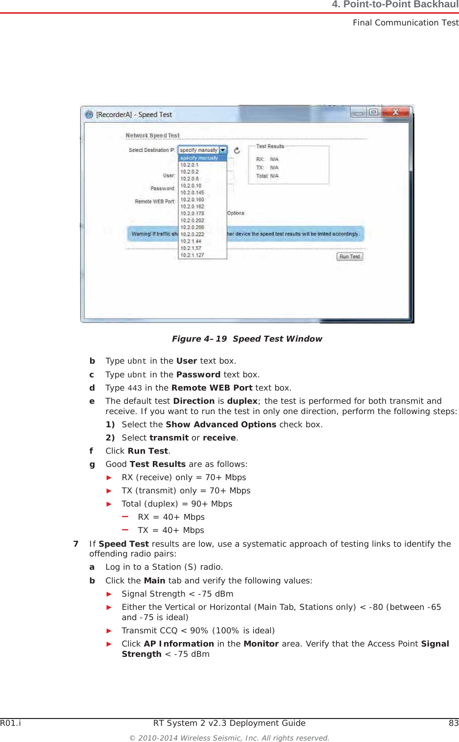
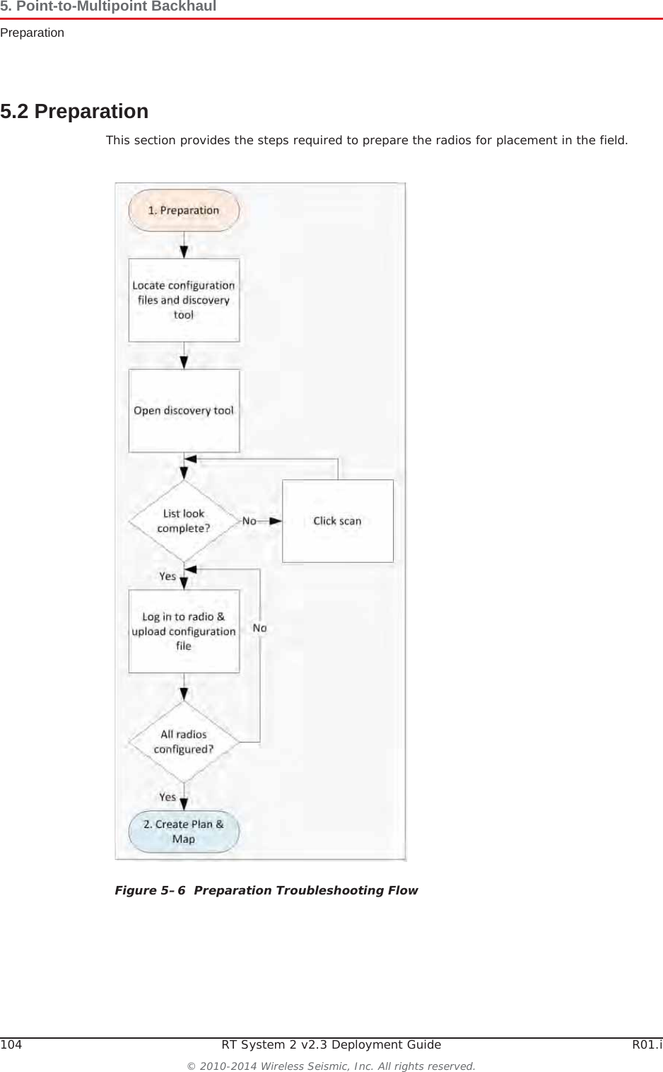
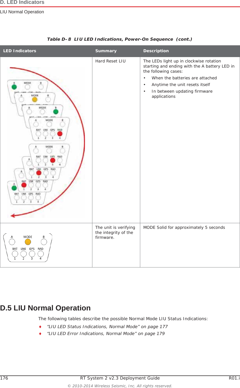
![R01.i RT System 2 v2.3 Deployment Guide 51© 2010-2014 Wireless Seismic, Inc. All rights reserved.3. BackhaulSetting up the BackhaulƔIf the wind is blowing, the mast is more stable when the brackets are perpendicular to the wind.5Secure the base [B-1] to the ground with stakes [BK-4] or nails [BK-6]. 6Attach the mast [M-3] to the base [B-1]. Tighten both knobs [B-2].Table 3–10 How to Set Up the BackhaulStep Image](https://usermanual.wiki/Wireless-Seismic/00105/User-Guide-2256184-Page-51.png)
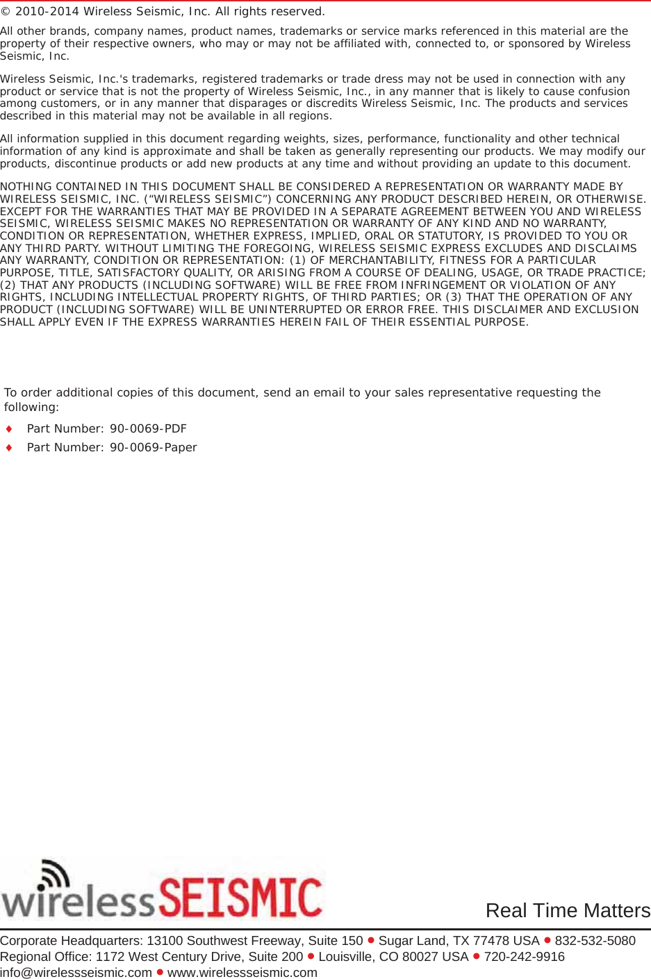
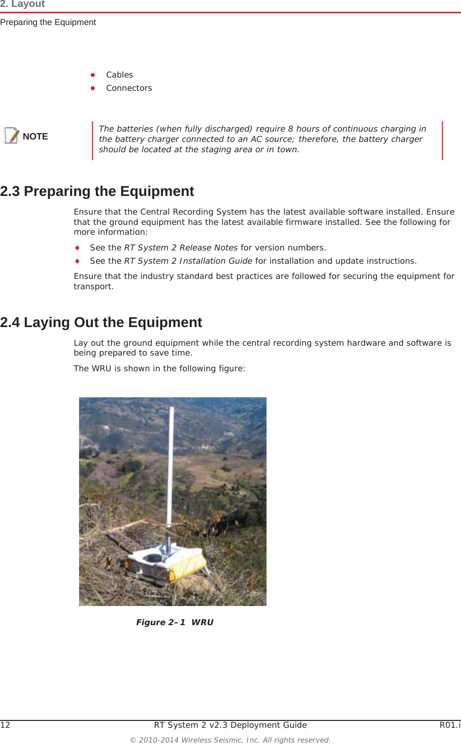
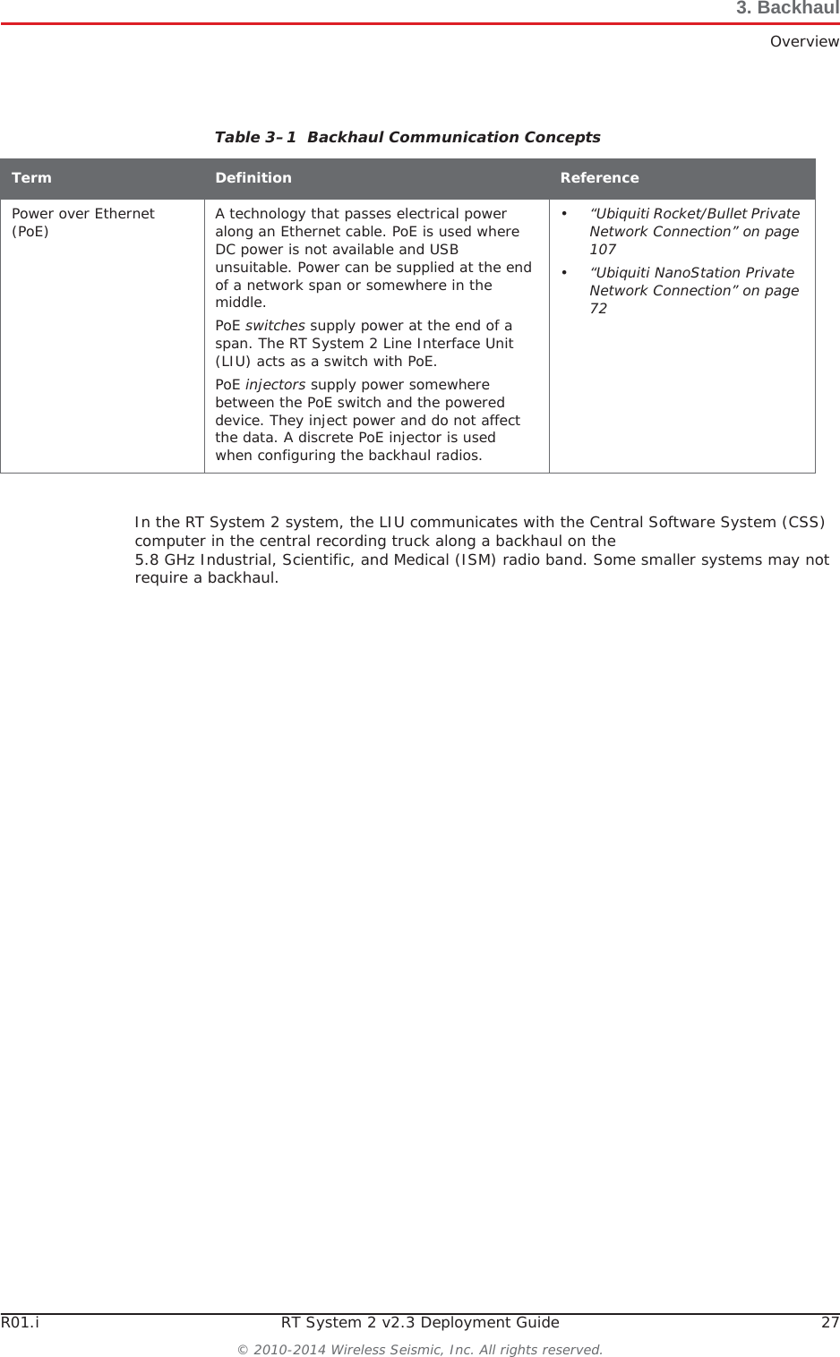
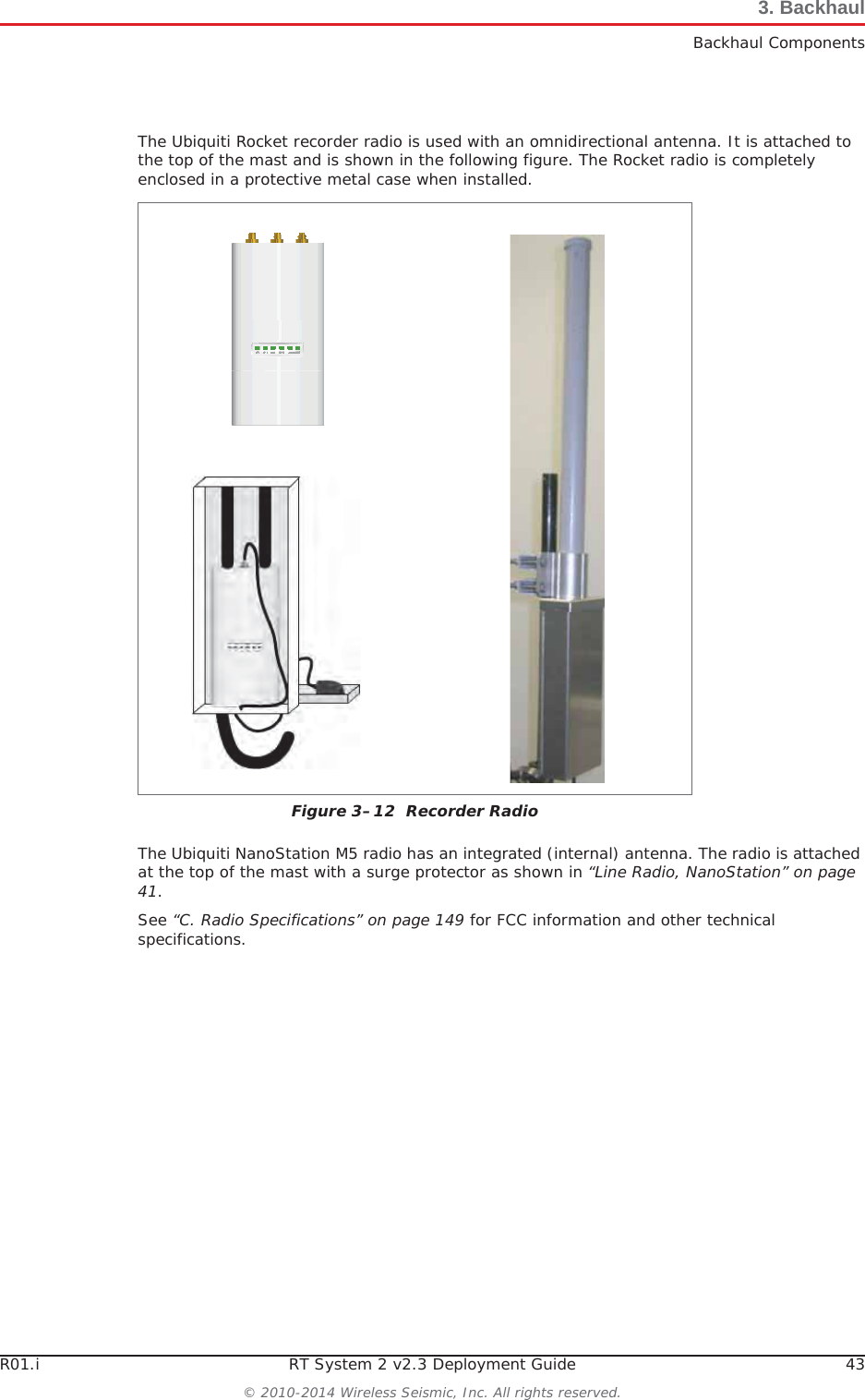
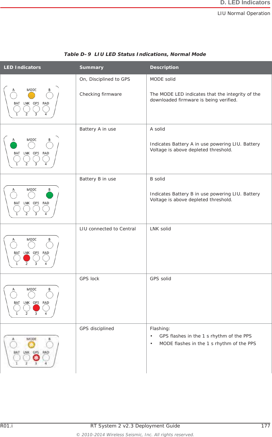
![52 RT System 2 v2.3 Deployment Guide R01.i© 2010-2014 Wireless Seismic, Inc. All rights reserved.3. BackhaulSetting up the Backhaul7Position four stakes equal distances apart at approximately 20 ft (6 m) from the base. Pound them into the ground. 8Assemble the radios and brackets:ƔBullet line radio installation – Assemble the Bullet radios and brackets.ŹInsert the 4 in hose clamp [LR-11] in the side slots of the bracket [LR-6].ŹInsert the 2 in hose clamp [LR-12] in the center slots of the bracket [LR-6].ŹInsert the line radio between the bracket [LR-6] and the 2 in hose clamp [LR-12].ŹTighten the 2 in hose clamp [LR-12]around the radio. Line radio in bracket:Table 3–10 How to Set Up the BackhaulStep Image](https://usermanual.wiki/Wireless-Seismic/00105/User-Guide-2256184-Page-52.png)
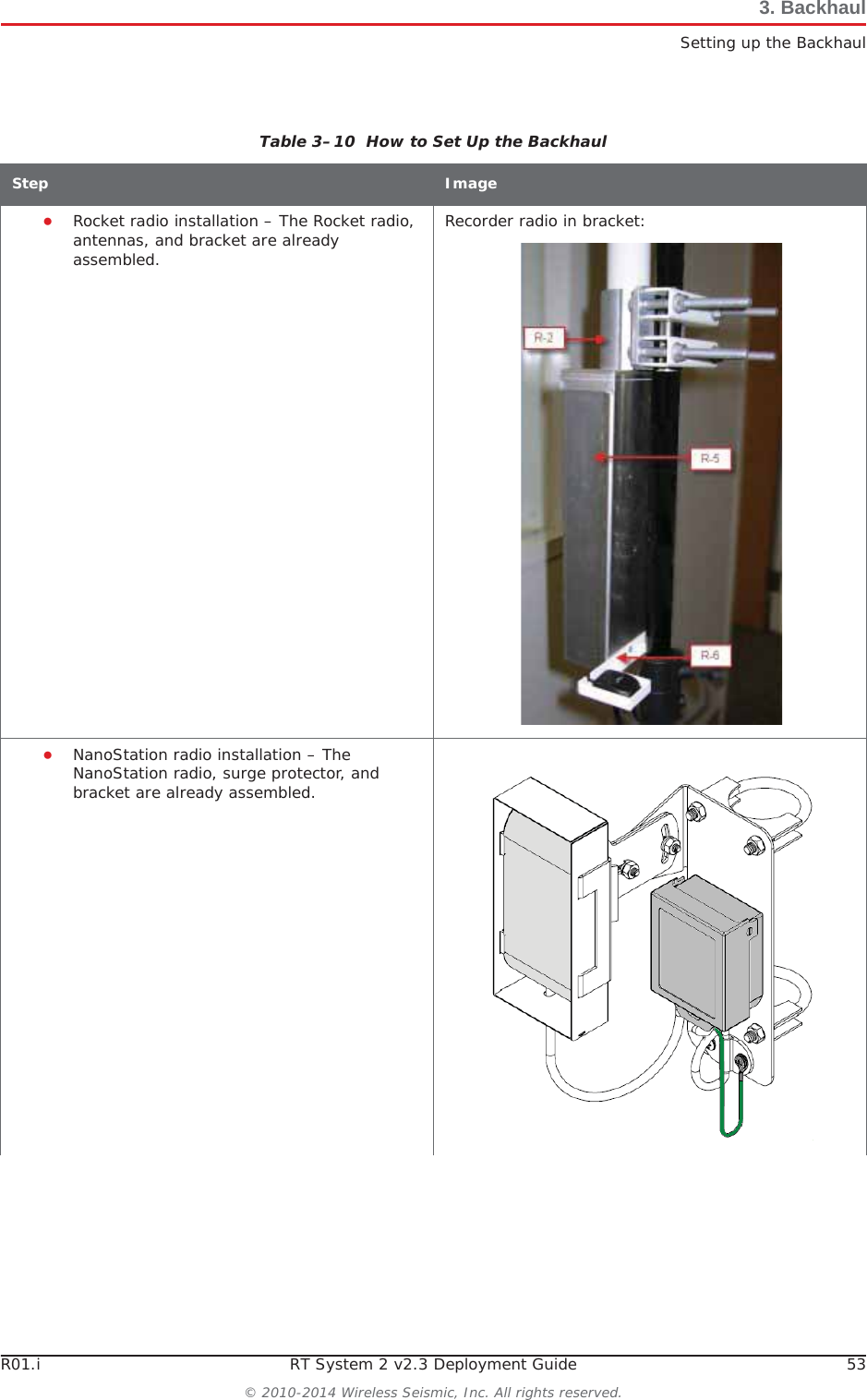
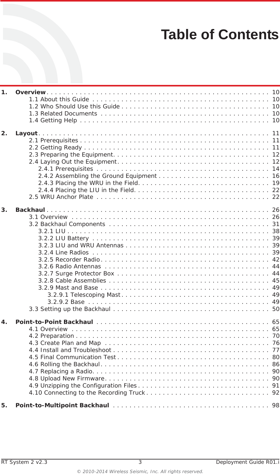
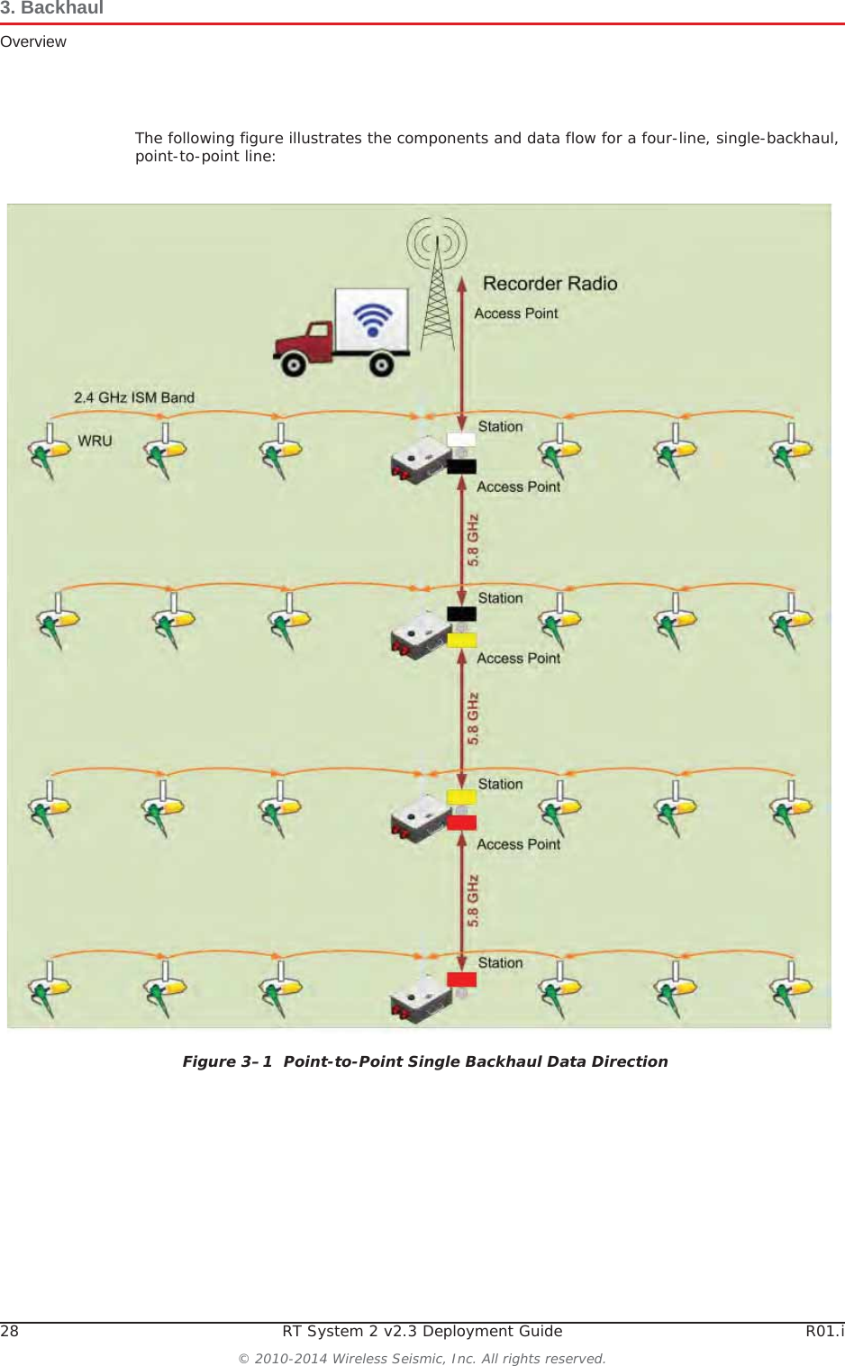
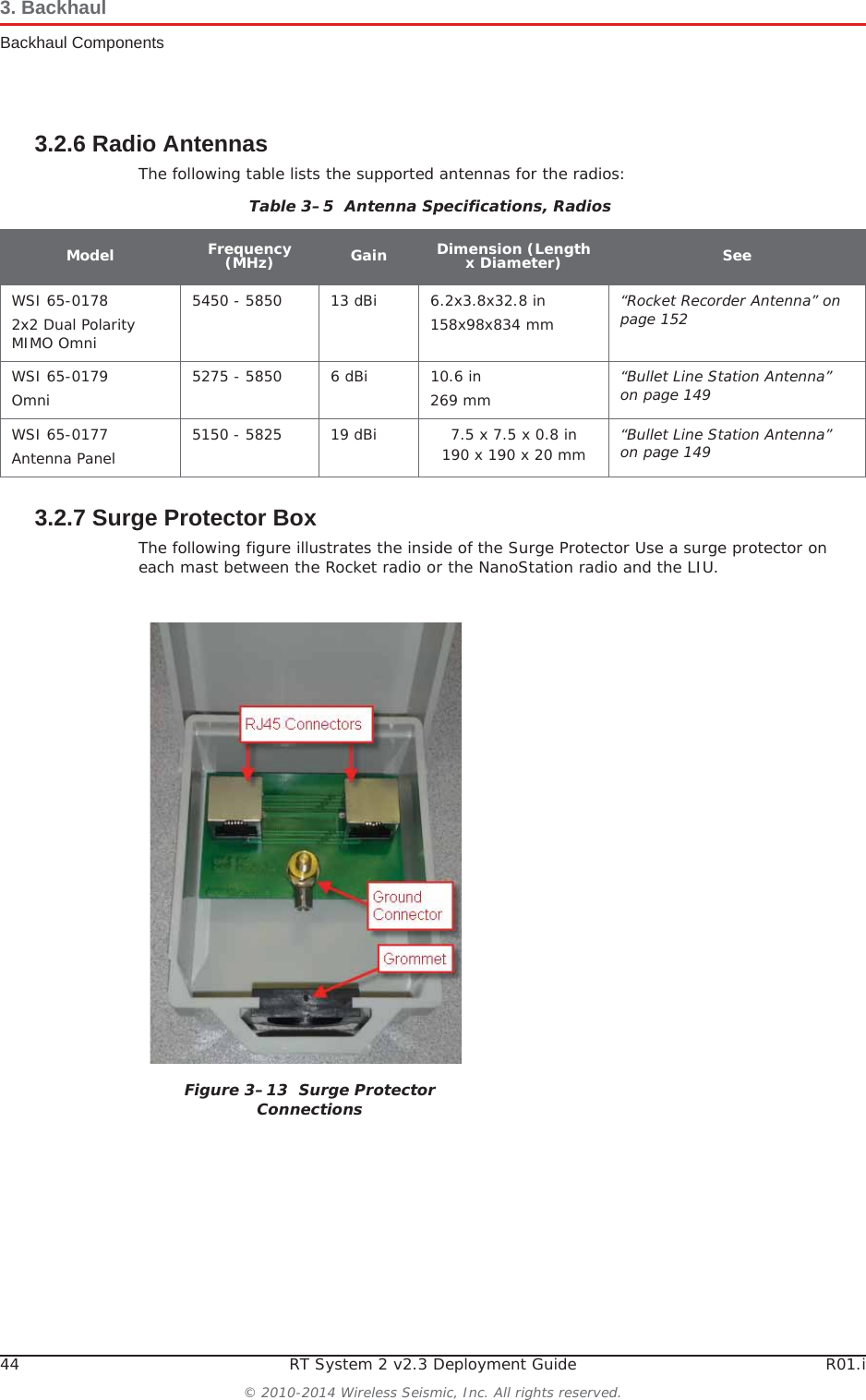
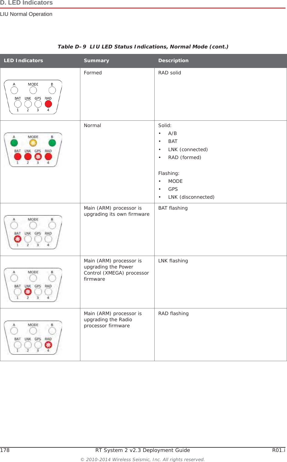
![54 RT System 2 v2.3 Deployment Guide R01.i© 2010-2014 Wireless Seismic, Inc. All rights reserved.3. BackhaulSetting up the Backhaul9Assemble the mast:ƔBullet radio installation – While the mast is resting on the ground, slide the following on the mast:ŹBullet radios and clamps (do not tighten)ŹMast guy ring [M-4]Table 3–10 How to Set Up the BackhaulStep Image](https://usermanual.wiki/Wireless-Seismic/00105/User-Guide-2256184-Page-54.png)
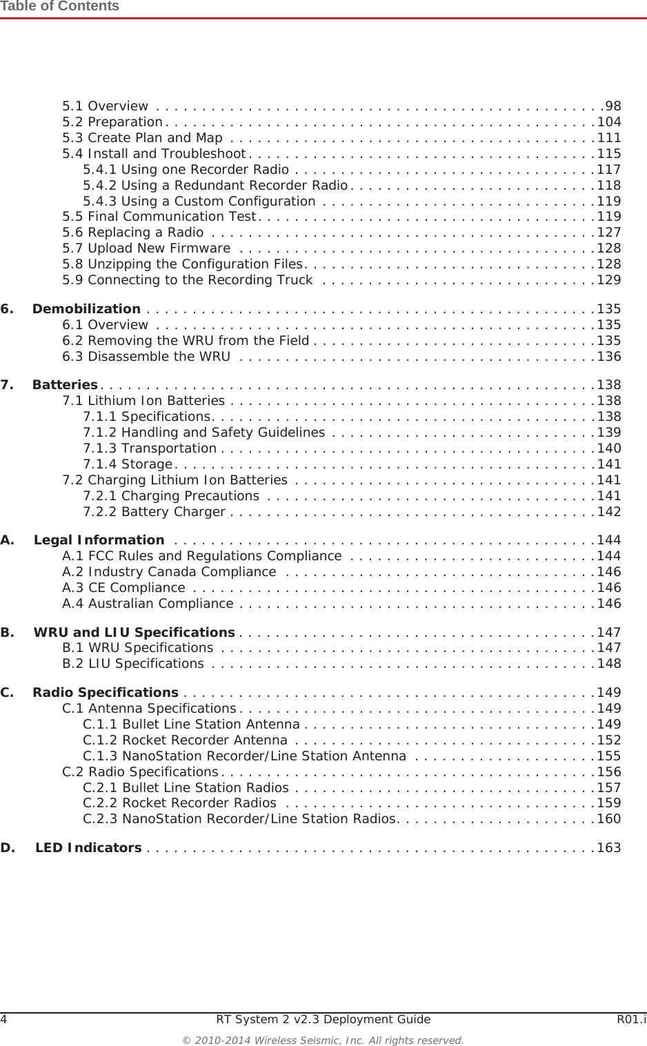
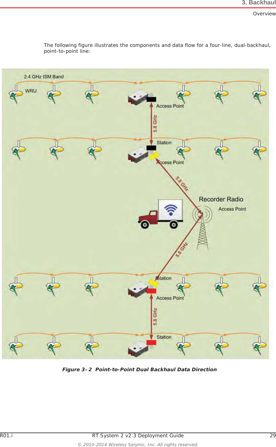
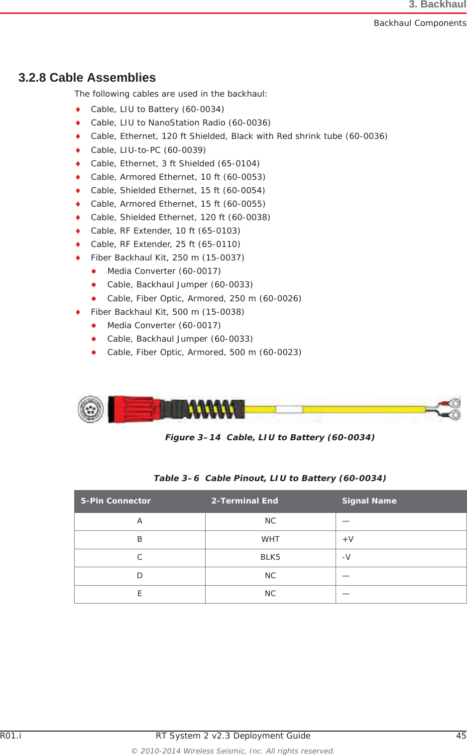
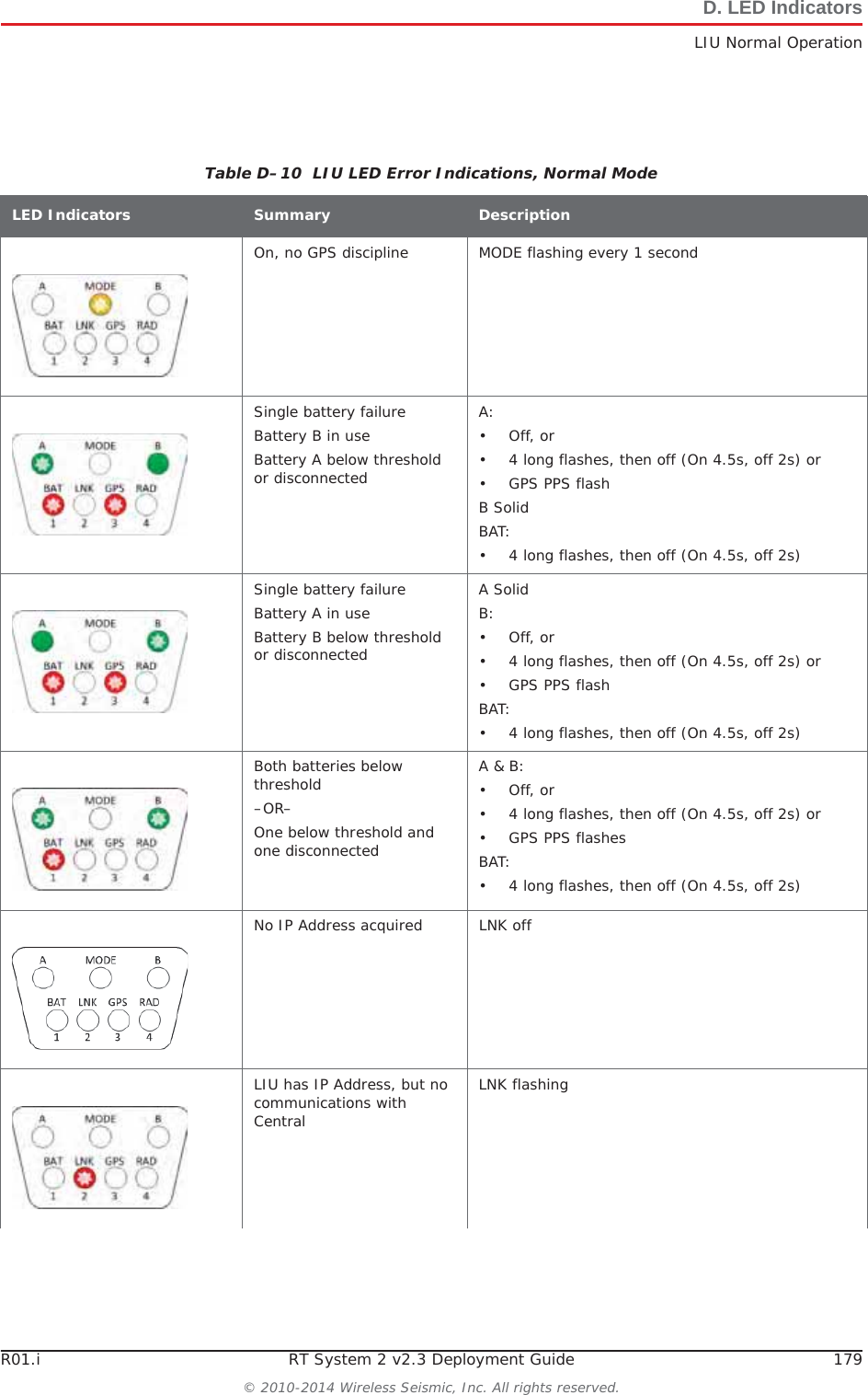
![R01.i RT System 2 v2.3 Deployment Guide 55© 2010-2014 Wireless Seismic, Inc. All rights reserved.3. BackhaulSetting up the BackhaulƔRocket radio installation – While the mast is resting on the ground, slide the following on the mast:ŹMast guy ring [M-4] ŹSurge Protector cable clamp (do not tighten)Table 3–10 How to Set Up the BackhaulStep Image](https://usermanual.wiki/Wireless-Seismic/00105/User-Guide-2256184-Page-55.png)
![56 RT System 2 v2.3 Deployment Guide R01.i© 2010-2014 Wireless Seismic, Inc. All rights reserved.3. BackhaulSetting up the BackhaulƔNanoStation radio installation – While the mast is resting on the ground, slide the following on the mast:ŹMast guy ring [M-4] 10 Attach and tighten the following:ƔBullet radio installation:ŹBullet radio antenna brackets and antennas [LR-4, LR-5]ŹOmni antenna bracket [M-5] and antenna [LR-3]Table 3–10 How to Set Up the BackhaulStep Image](https://usermanual.wiki/Wireless-Seismic/00105/User-Guide-2256184-Page-56.png)
![R01.i RT System 2 v2.3 Deployment Guide 57© 2010-2014 Wireless Seismic, Inc. All rights reserved.3. BackhaulSetting up the BackhaulƔRocket radio installation – Attach the Rocket radio antenna and bracket [R-2] to the mast.Table 3–10 How to Set Up the BackhaulStep Image](https://usermanual.wiki/Wireless-Seismic/00105/User-Guide-2256184-Page-57.png)
![58 RT System 2 v2.3 Deployment Guide R01.i© 2010-2014 Wireless Seismic, Inc. All rights reserved.3. BackhaulSetting up the BackhaulƔNanoStation radio installation – Attach the NanoStation radio bracket assembly [RN-2] to the mast.Table 3–10 How to Set Up the BackhaulStep Image](https://usermanual.wiki/Wireless-Seismic/00105/User-Guide-2256184-Page-58.png)
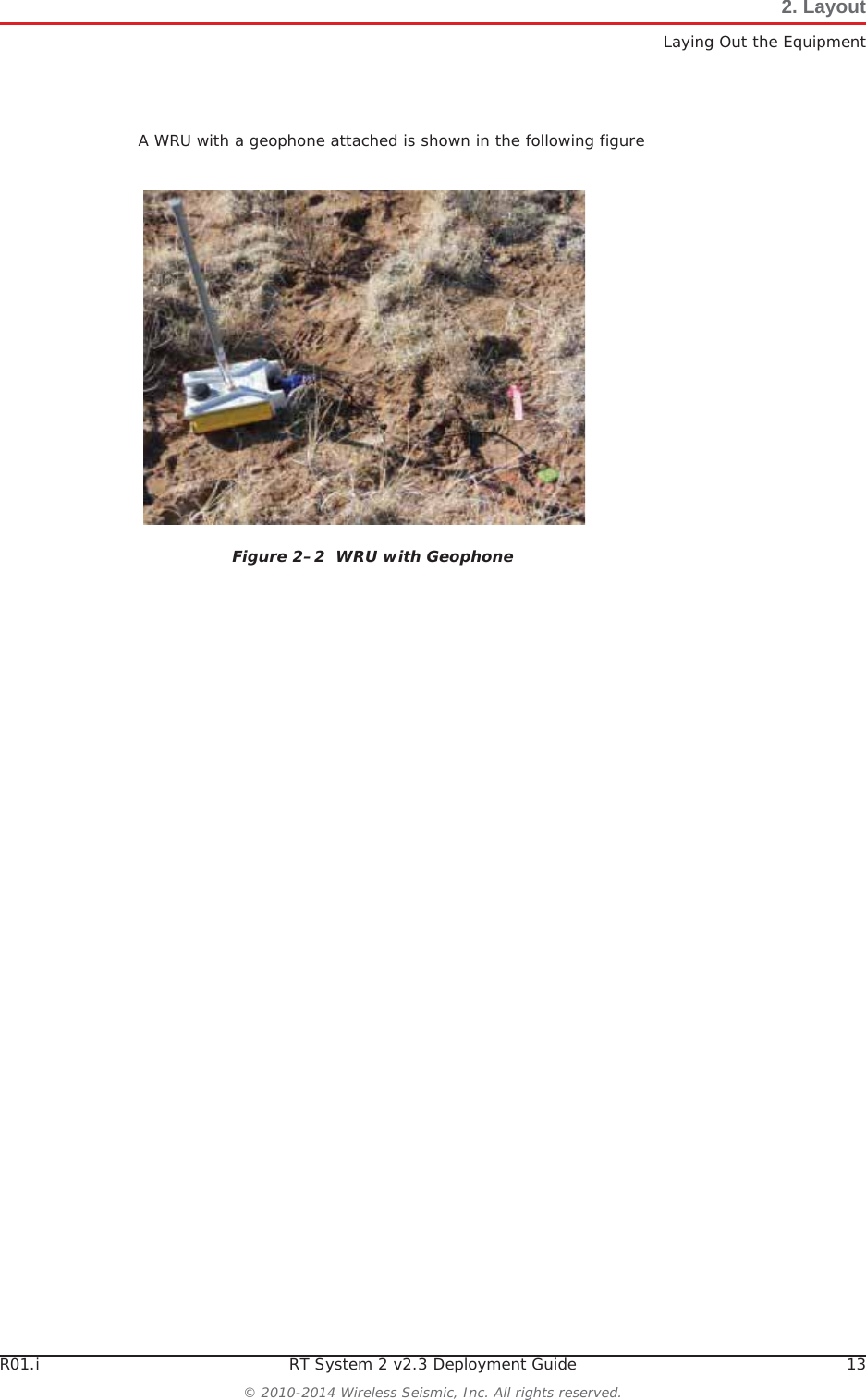
![R01.i RT System 2 v2.3 Deployment Guide 59© 2010-2014 Wireless Seismic, Inc. All rights reserved.3. BackhaulSetting up the Backhaul11 Attach the cables:ƔBullet radio installation – Attach an elbow connector [LR-14] to the antenna and then an armored cable [LR-7, LR-8] to the elbow connector. Match white-to-white and green-to-green if your panels are color-coded. ƔRocket radio installation:ŹOpen the protective metal case if the Ethernet cable is not already attached.ŹConnect the GPS antenna if it is not already connected.ŹConnect a short Ethernet cable [R-8] to the radio [R-3]. ŹClose the protective metal case.ŹOpen the surge protector case [R-9]. ŹRemove the rubber grommet from the surge protector case and cut some slots in it. ŹThread two Ethernet cables [R-8, R-10] and a ground wire [BK-14] through the grommet and place the grommet back in the case.ŹPlug the Ethernet cables into the shielded RJ45 jacks. It does not matter which cable goes to which jack; the unit provides bidirectional protection.ŹAttach the ground wire to the ground lug.ŹClose the surge protector case and secure it to the mast with the hose clamp.Table 3–10 How to Set Up the BackhaulStep Image](https://usermanual.wiki/Wireless-Seismic/00105/User-Guide-2256184-Page-59.png)
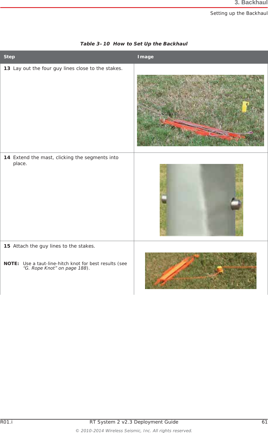
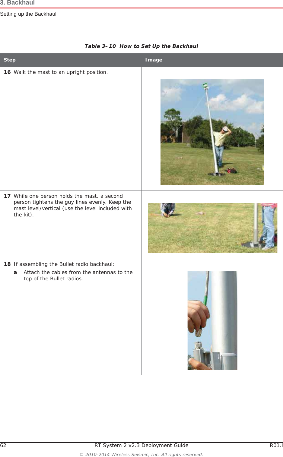
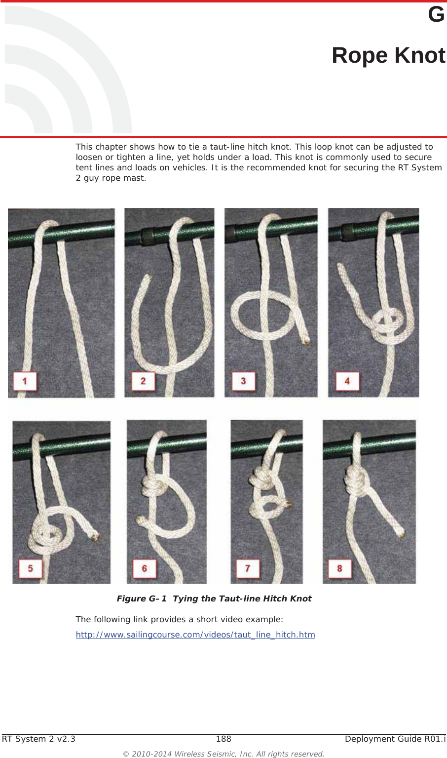
![60 RT System 2 v2.3 Deployment Guide R01.i© 2010-2014 Wireless Seismic, Inc. All rights reserved.3. BackhaulSetting up the BackhaulƔNanoStation radio installation:ŹOpen the surge protector case [R-9]. ŹRemove the grommet from the case.ŹThread the Ethernet cable [RN-3], through the grommet with the short Ethernet cable (that is attached to the redound the ground wire [BK-14]. Place the grommet back in the case.ŹPlug the Ethernet cable into the shielded RJ45 jacks. It does not matter which cable goes to which jack; the unit provides bidirectional protection.ŹClose the surge protector case.ŹAttache the strain relief [RN-4] to the D-ring on the bracket.ŹLoop the Ethernet Cable [RN-3] through the strain relief [RN-4].12 Attach the guy lines to the mast collar.NOTE: Use a taut-line-hitch knot for best results (see “G. Rope Knot” on page 188). Table 3–10 How to Set Up the BackhaulStep Image](https://usermanual.wiki/Wireless-Seismic/00105/User-Guide-2256184-Page-60.png)


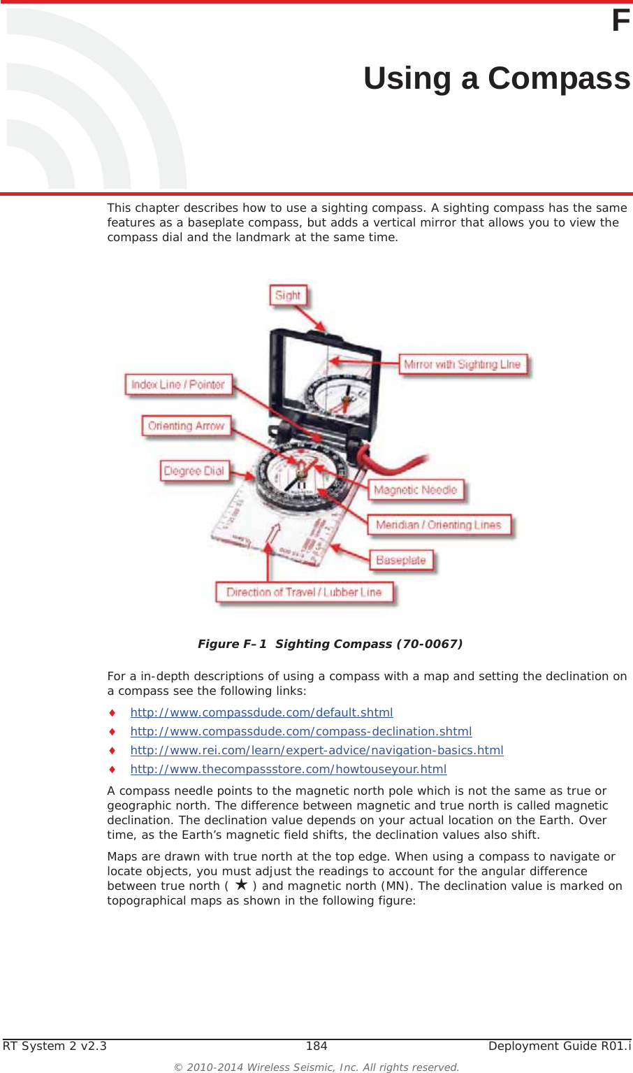
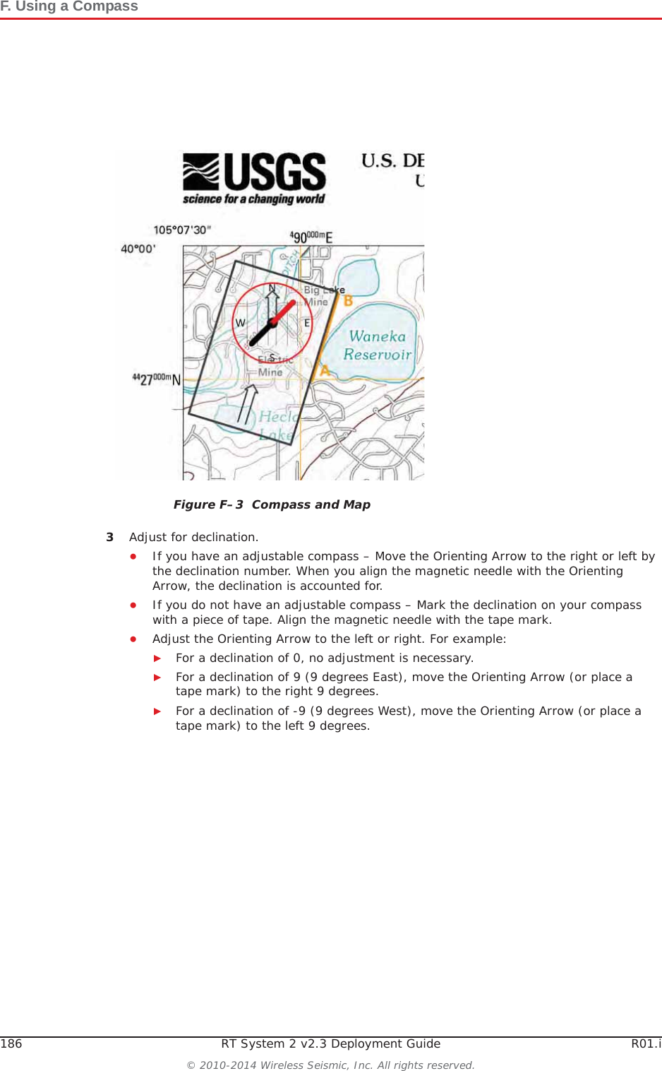
![R01.i RT System 2 v2.3 Deployment Guide 185© 2010-2014 Wireless Seismic, Inc. All rights reserved.F. Using a CompassHowever, because of the dynamic nature of the Earth’s magnetic field, old maps are inaccurate. To obtain the most recent declination values, enter your map location at the following link:http://www.ngdc.noaa.gov/geomag-web/#declinationTo locate an object using a map and a compass:1Place the long edge of the compass baseplate on the map, connecting the desired start and end points. For example, the start point could be where you are standing [A], and the end point [B] is where you want to locate the backhaul mast. The Direction of Travel arrow should point towards the end point (mast location). 2While holding the compass on the map, turn the Degree Dial until the Meridian / Orienting Lines are parallel with the Meridian lines on the map. This is the same as turning the Degree Dial until the Orienting Arrow points to north on the map. Figure F–2 Declination Indication on MapNOTE Placing magnetic objects near a compass can cause an incorrect reading (deviation). Examples include:• Objects that contain steel and iron such as pocket knives, belt buckles, vehicles, railroad tracks, and ore deposits in the Earth• Objects that use magnets such as stereo speakers• Electrical current in cables and overhead lines](https://usermanual.wiki/Wireless-Seismic/00105/User-Guide-2256184-Page-185.png)

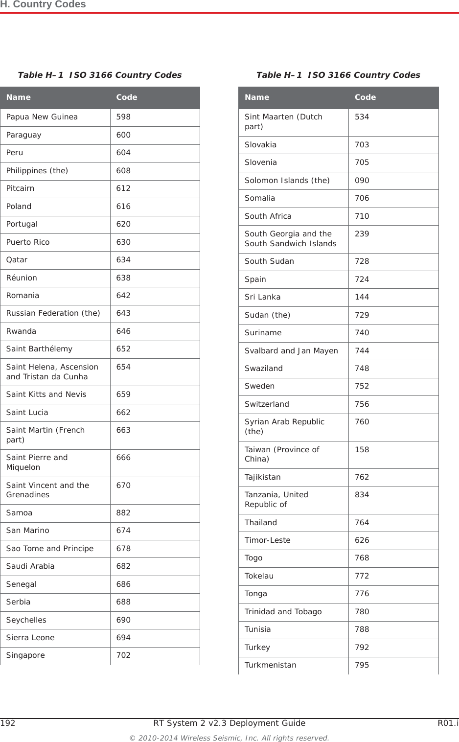
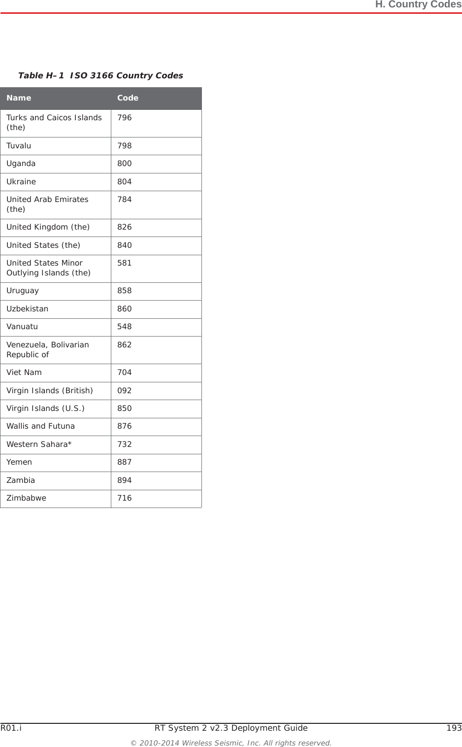
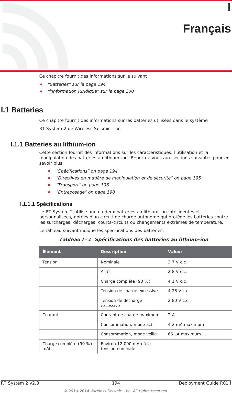
![H. Country Codes190 RT System 2 v2.3 Deployment Guide R01.i© 2010-2014 Wireless Seismic, Inc. All rights reserved.Congo (the Democratic Republic of the) 180Cook Islands (the) 184Costa Rica 188Côte d'Ivoire 384Croatia 191Cuba 192Curaçao 531Cyprus 196Czech Republic (the) 203Denmark 208Djibouti 262Dominica 212Dominican Republic (the) 214Ecuador 218Egypt 818El Salvador 222Equatorial Guinea 226Eritrea 232Estonia 233Ethiopia 231Falkland Islands (the) [Malvinas] 238Faroe Islands (the) 234Fiji 242Finland 246France 250French Guiana 254French Polynesia 258French Southern Territories (the) 260Gabon 266Gambia (The) 270Table H–1 ISO 3166 Country CodesName CodeGeorgia 268Germany 276Ghana 288Gibraltar 292Greece 300Greenland 304Grenada 308Guadeloupe 312Guam 316Guatemala 320Guernsey 831Guinea 324Guinea-Bissau 624Guyana 328Haiti 332Heard Island and McDonald Islands 334Holy See (the) [Vatican City State] 336Honduras 340Hong Kong 344Hungary 348Iceland 352India 356Indonesia 360Iran (the Islamic Republic of) 364Iraq 368Ireland 372Isle of Man 833Israel 376Italy 380Jamaica 388Table H–1 ISO 3166 Country CodesName Code](https://usermanual.wiki/Wireless-Seismic/00105/User-Guide-2256184-Page-190.png)