Wireless eSystems IRESPONDREMOTE Model TR101 User Manual 481330
Wireless eSystems, Inc. Model TR101 481330
user manual

UM04725
June 7, 2004
Rev -
USERS MANUAL
FOR THE
IRESPOND SYSTEM
Prepared by:
65 Hill Ave.
Fort Walton Beach, FL 32548
(850) 244-2332
Email: www.wirelessesystems.net
Note: This equipment has been tested and found to comply with the limits for a class B
digital device, pursuant to Part 15 of the FCC Rules. These limits are designed to
provide reasonable protection against harmful interference in a residential
installation. This equipment generates, uses and can radiate radio frequency
energy and, if not installed and used in accordance with the instructions, may
cause harmful interference to radio communications. However, there is no
guarantee that interference will not occur in a particular installation. If this
equipment does cause harmful interference to radio or television reception, which
can be determined by turning the equipment off and on, the user is encouraged to
try to correct the interference by one of the following measures:
• Reorient or relocate the receiving antenna.
• Increase the separation between the equipment and receiver
• Connect the equipment into an outlet on a circuit different from that to
which the receiver is connected
• Consult the dealer or an experienced radio/TV technician for help
Changes or modifications not expressly approved by Micro Systems Inc. could
void the user's authority to operate the equipment.
UM04725
June 7, 2004
Rev -
i
TABLE OF CONTENTS
Paragraph Title Page
1.0 SCOPE 1
2.0 SYSTEM OVERVIEW 1
2.1 Base Station Description 2
2.2 Base Station Set Up 2
2.3 Remote Description 3
2.4 Remote Operation 5
2.5 Battery Charging 5
2.6 Battery Pack Replacement 6
LIST OF FIGURES
Figure Title Page
1 IRespond Operation 1
2 Base Station 2
3 Base Station Display 3
4 Remote Features 4
5 Battery Charger 6
6 Battery Pack Replacement 7
LIST OF TABLES
Table Title Page
I Keypad Functions 4
LIST OF ACRONYMS
AC Alternating Current
DC Direct Current
ID Identification
LCD Liquid Crystal Display
PC Personal Computer
RF Radio Frequency
RSS Rapid Scoring System
SIM Student Interactive Module
UM04725
June 7, 2004
Rev -
1
1.0 SCOPE. This document provides information on the setup and operation of the
IRespond System. The IRespond System is used in a classroom environment to allow an
instructor to automate the test taking and grading process.
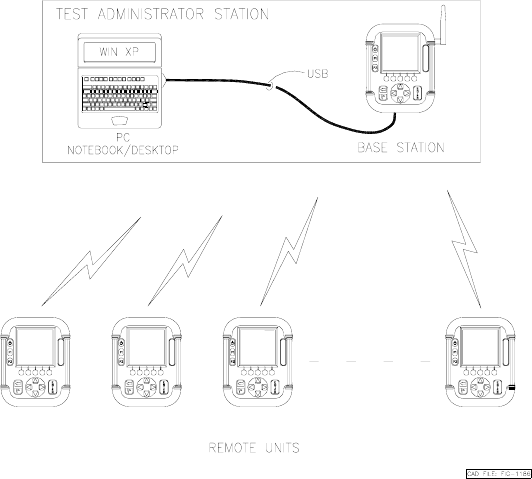
2.0 System Overview. The IRespond System consists of a single base station, thirty
hand held remote modules and a software package which executes on a personal
computer (PC) with a Windows XP operating system. The software package administers
tests and questions from the instructor’s PC to the individual remote users. The handheld
units communicate over a wireless Radio Frequency (RF) link to a base station and
utilize rechargeable batteries for “ no wires” operation. Figure 1. illustrates the IRespond
System operation.
Figure 1. IRespond System Operation
UM04725
June 7, 2004
Rev -
2
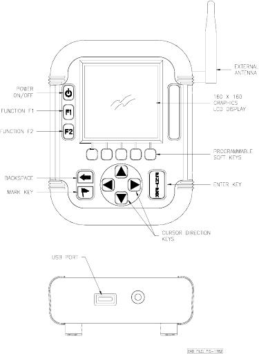
2.1 Base Station Description. The base station controls message traffic flow
between the PC and the Remote units. Note that the base station is a modified version of
the Remote. A Universal Serial Bus (USB) interface and and a different software
package are the major differences between the base station and Remote physically. The
Liquid Crystal Display (LCD) display and keypad are used for diagnostic test and status
display on the base station. Also the base station features an external antenna. Figure 2
illustrates the features of the base station.
A
E
S
B
Figure 2. IRespond Base Station
The base station contains software to collect and distribute information between the
Remotes and the IRESPOND software package on the PC. The software has two main
functions; first the software manages the radio frequency traffic between the devices and
then secondly communicate data to the PC via the USB port.
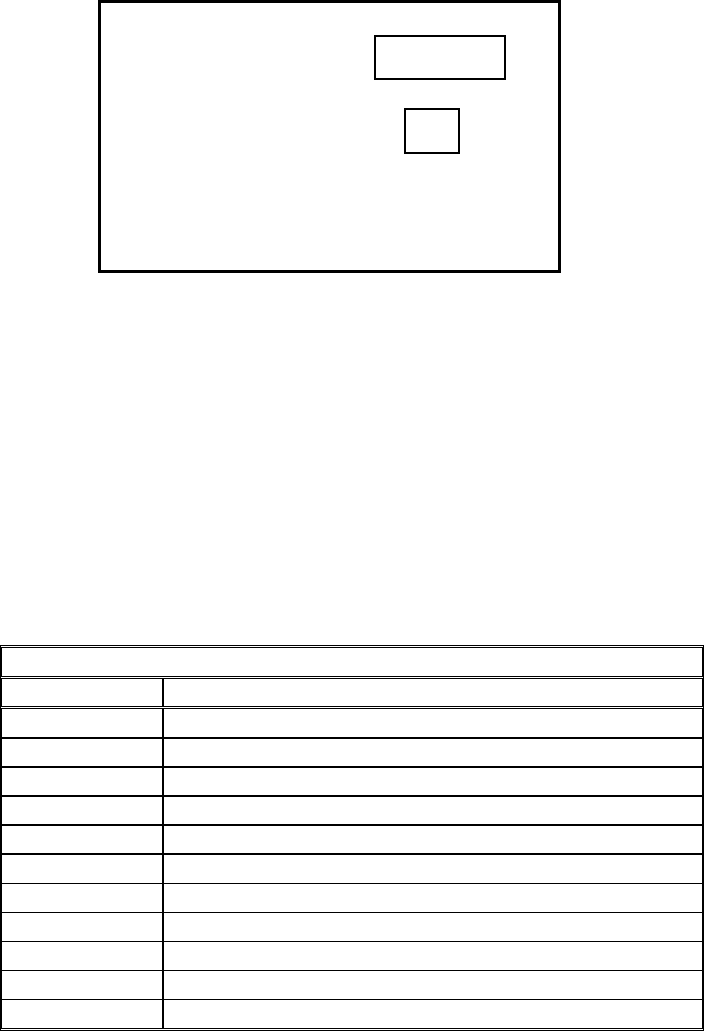
Base Station Set Up. Connect the supplied USB cable to the base station USB
connector at the bottom of the unit. The base station derives DC power from the USB
port. Press the power button to power the unit on. A second key press to the power
switch will turn the unit off. The base station will display connection status to the PC
USB link and status of the RF links indicating by the universal identification number for
each Remote device logged into the base station.This display is shown in Figure 3.
UM04725
June 7, 2004
Rev -
3
Figure 3. Base Station Display
2.3 Remote Module Description. The Remote provides the data entry point for the
user of the IRespond system. The LCD graphics display, the programmable soft keys and
cursor keys allow the user to quickly enter data for transmittal to the base station. Figure
4 shows the Remote features. Table I below explains the keypad assignments.
Table I. Keypad Functions
KEY FUNCTION
Power applies power to unit
F1 programmable function key
F2 programmable function key
S1-S5 programmable soft keys , for answer selection
Backspace move cursor to previous position
Flag mark undecided answer
up arrow cursor up
right arrow cursor right
down arrow cursor down
left arrow cursor left
enter execute
USB Connection:
Remotes Active:
2378e9
112ca8
ACTIVE
02
UM04725
June 7, 2004
Rev -
4
E
T
O
M
E
R
Figure 4. Remote Features
To turn the unit on press the power key. To turn the unit off, press the power key again.
Note that during testing the power off function is disabled until the test time has elapsed
or enabled by the base station.
2.4 Remote Operation. The Remote units operate in concert with the base station,
therefore the base station must be powered on and communication established with the
IRESPOND application prior to Remote activation. When the Remote user turns on the
unit the device requests the user to enter his or her personal User Identification (ID) and
password using the virtual keyboard display. Upon completion of this information , the
ID and password are sent to IRESPOND. Upon recognizing the user the IRESPOND
system will pass back the test the user is assigned.
The test can be displayed to the user in two ways. First is at a summary level that lists the
test question number and shows the answer choice selected, if any. The second is a detail
question level that shows the question number, the first 20 characters of the test question,
and the answer choices below. The second level is where the user will actually take the
test. For example, the user will review the first question and decide which answer choice
to select and press the button on the hand held Remote. Once the selection is made, the
answer selected will change shape and then the SIM will move to the next question.
Periodically the Base station will poll the devices and collect information. The answers
selected by the user will be retrieved and temporarily stored by the base station. In
UM04725
June 7, 2004
Rev -
5
addition, information about the user, the number of questions answered/remaining, and
the device number the user is employing can be displayed on the personal computer
display.
When the user has completed the test, the user will submit the test for scoring. The
Remote will deliver any remaining or updated information to the Base Unit PC. This
information will be passed through to IRESPOND for immediate grading and storage.
Once the test has been graded the instructor will have the ability to immediately review
results and/or print reports.
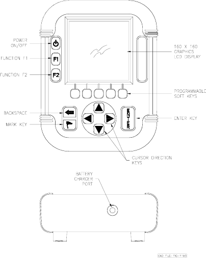
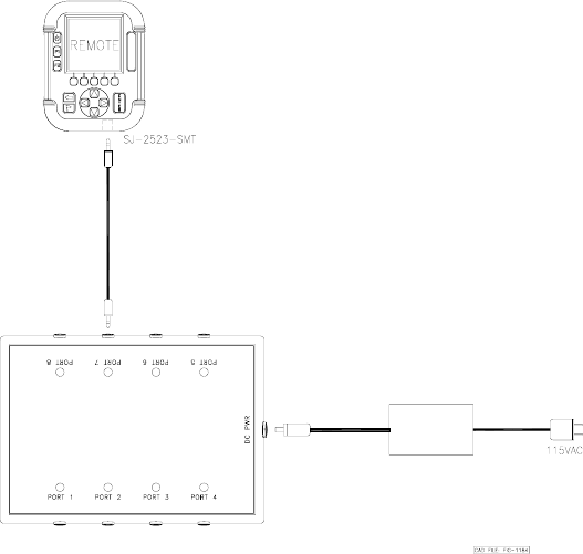
2.5 Battery Charging. The Remote units are shipped with battery packs installed but
uncharged. The battery charger is capable of bringing a battery pack from completely
discharged to fully charged in approximately 3 hours. The Remote utilizes NiMH
batteries in a 3 cell configuration. The Remote provides a low battery indication when the
batteries reach 20% of capacity. Battery life is dependent upon operator use. The battery
charger is connected to the Remote with a short 2 foot cable. One end of the cable has a 3
pin connector which inserts into the battery charger. The other end of the cable has a
single prong audio jack connector which is inserted into one end of the Remote. The
remote is not powered on during charging. While charging the battery charger will
illuminate a red LED. When charging is complete the red LED will extinguish. The
battery charger and cable are shown in Figure 5.
R
E
M
O
T
E
Figure 5. Battery Charger
UM04725
June 7, 2004
Rev -
6
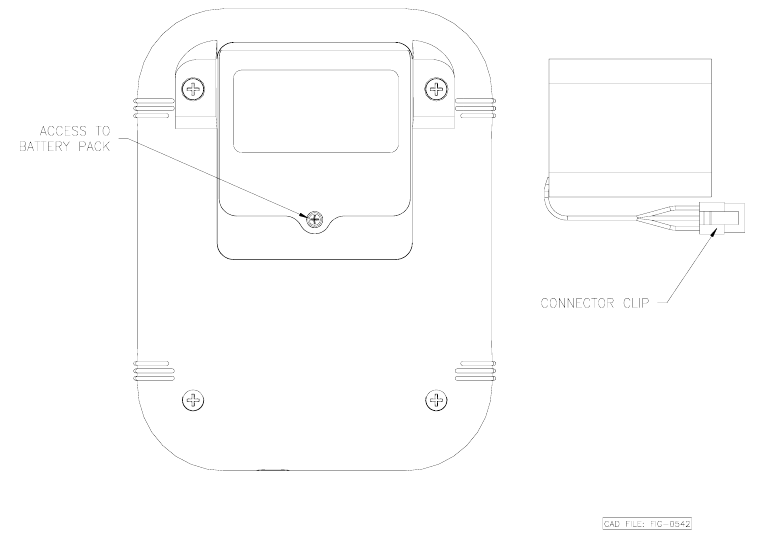
2.6 Battery Pack Replacement. In the event that a battery pack will not remain
charged and needs replacement then refer to Figure 6. Place the Remote on a flat surface
with the display face down exposing the battery pack compartment on the rear of the
Remote. Remove the battery cover screw with a cross tip screw driver. Press down on
the battery pack connector clip on the pack in the unit. Gently remove the battery pack
connector clip and remove the battery pack. Insert the new battery pack connector clip
onto the mate within the unit ensuring that the clip snaps into place. Put the battery pack
into the battery compartment. Replace the battery cover and re-install the battery cover
screw.
Figure 6. Battery Pack Replacement