Wireless eSystems RSS97735SIM User Manual
Wireless eSystems, Inc.
User Manual

FCCUM99725
March 15, 2000
Rev -
USERS MANUAL
FOR THE
RAPID SCORING SYSTEM (RSS)
Prepared by:
35 Hill Ave.
Fort Walton Beach, FL 32548
(850) 244-2332
Email: www.gomicrosystems.com
FCCUM99725
March 15, 2000
Rev -
i
TABLE OF CONTENTS
Paragraph Title Page
1.0 SCOPE 1
2.0 SYSTEM OVERVIEW 1
2.1 Base Station Description 2
2.2 Base Station Set Up 2
2.3 Remote Interactive Module Description 3
2.4 Remote Operation 5
2.5 Battery Charging 5
2.6 Battery Pack Replacement 6
LIST OF FIGURES
Figure Title Page
1 RSS Operation 1
2 RSS Base Station 2
3 Base Station Display 3
4 Remote Features 4
5 Battery Charger 6
6 Battery Pack Replacement 7
LIST OF TABLES
Table Title Page
I Keypad Functions 4
LIST OF ACRONYMS
AC Alternating Current
DC Direct Current
ID Identification
LCD Liquid Crystal Display
PC Personal Computer
RF Radio Frequency
RSS Rapid Scoring System
FCCUM99725
March 15, 2000
Rev -
1
1.0 SCOPE. This document provides information on the setup and operation of the
Rapid Scoring System (RSS).
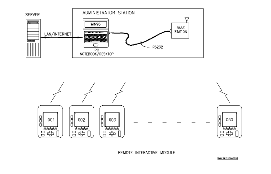
2.0 System Overview. The RSS consists of a single base station, thirty hand held
remote interactive modules and a software package which executes on a personal
computer (PC) with a Windows95/98 operating system. The software package will also
run on a Macintosh PC. The software package is designed to communicate over a local
area network with a server running the software included. The handheld units
communicate over a wireless Radio Frequency (RF) link to a base station and utilize
rechargeable batteries for “ no wires” operation. Figure 1. illustrates the RSS operation.
Figure 1. RSS Operation
FCCUM99725
March 15, 2000
Rev -
2
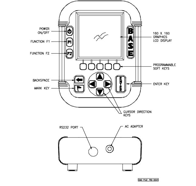
2.1 Base Station Description. The base station controls message traffic flow
between the PC and the remote units. Note that the base station is a modified version of
the remote. An RS232 interface, Alternating Current (AC) wall adapter and a different
software package are the only differences between the base station and remote units. The
Liquid Crystal Display (LCD) display and keypad are used for diagnostic test and status
display on the base station. Figure 2 illustrates the features of the base station.
Figure 2. RSS Base Station
The base station contains software to collect and distribute information between the
remotes and the server. The software has two main functions; first the software manages
the radio frequency traffic between the devices and the PC. In addition , this software
writes records to and receives records from a local version on the base station The local
version is the middleware that takes information and reads/writes data into the master
server.
2.2 Base Station Set Up. Connect the supplied RS232 cable to the base station
circular DIN connector at the bottom of the unit. Connect the other end of the RS232
cable to the serial port of the PC. Connect the direct current (dc) jack on the end of the
AC adapter cable into the bottom of the base station. Connect the AC adapter into an AC
wall outlet. Press the power button to power the unit on. A second key press to the

FCCUM99725
March 15, 2000
Rev -
3
power switch will turn the unit off. The base station will display connection status to the
PC RS-232 link and status of the RF links, on the PC display, indicated by a flashing
circle for each remote which is responding to the base station. This base unit display is
shown in Figure 3.
Figure 3. Base Station Display
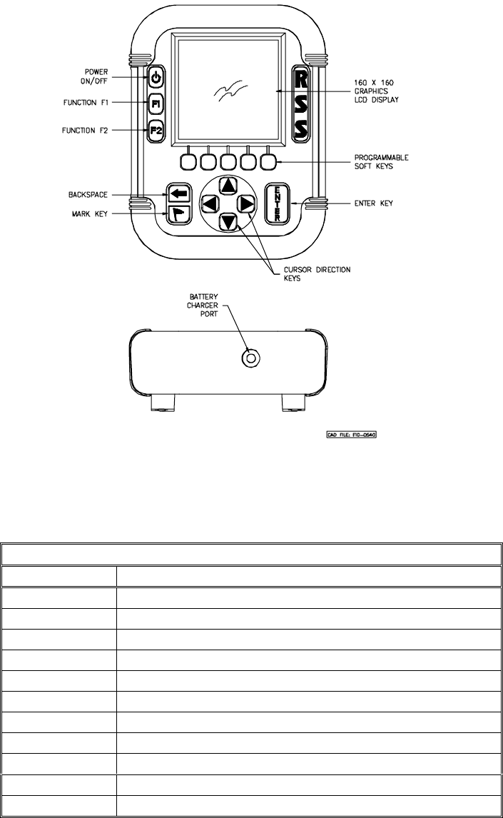
2.3 Remote Interactive Module Description. The remote provides the data entry
point for the user of the RSS system. The LCD graphics display, the programmable soft
keys and cursor keys allow the user to quickly enter data for transmittal to the server.
Figure 4 shows the remote features. Table I below explains the keypad assignments.
RSSM Connection:
Remote Connections Active:
ACTIVE
20
FCCUM99725
March 15, 2000
Rev -
4
Figure 4. Remote Features
Table I. Keypad Functions
KEY FUNCTION
Power applies power to unit
F1 programmable function key
F2 programmable function key
S1-S5 programmable soft keys , for answer selection
Backspace move cursor to previous position
Flag mark undecided answer
up arrow cursor up
right arrow cursor right
down arrow cursor down
left arrow cursor left
enter execute
FCCUM99725
March 15, 2000
Rev -
5
To turn the unit on, press the power key. To turn the unit off, press the power key again.
Note that during operation the power off function is disabled until the allotted time has
elapsed or enabled by the base station.
2.4 Remote Operation. The remote units operate in concert with the base station,
therefore the base station must be powered on and communication established with the
server prior to remote activation. When the remote user turns on the unit the device
requests the user to enter his or her personal User Identification (ID) and password using
the virtual keyboard display. Upon completion of this information , the ID and password
are sent to the server. Upon recognizing the user the server will pass back the options the
user is assigned. The user then scrolls the list of options and selects the appropriate one.
Once the option is selected, the server sends the selected items to the user.
Periodically the Base station will poll the devices and collect information. The
information entered by the user will be retrieved and temporarily stored by the base
station. In addition, information about the user and the device number the user is
operating can be displayed on the personal computer display.
When the user has completed the operation, the user will command the remote to deliver
any remaining or updated information to the Base Unit. This information will be passed
through to the master server for immediate evaluation. Once the information is processed
by the master server, the administrator will have the ability to sign on directly to the
master server to review results on-line and/or print reports.
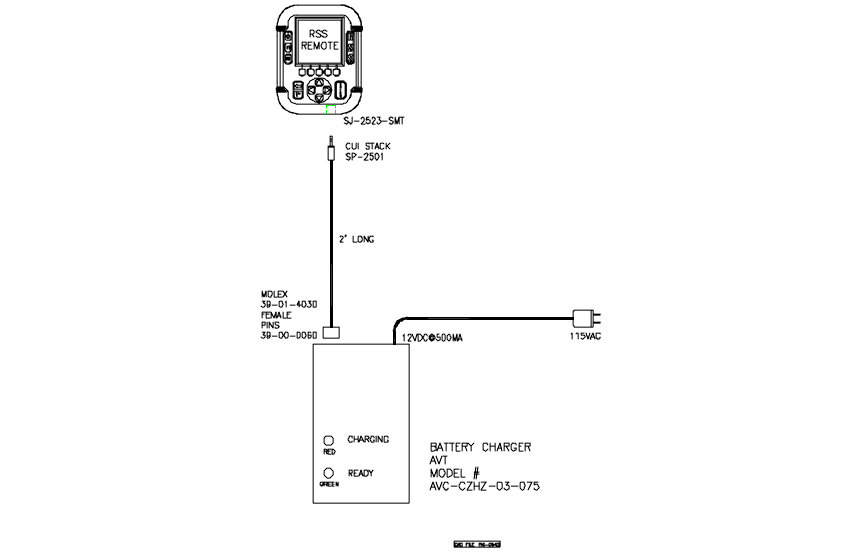
2.5 Battery Charging. The remote units are shipped with battery packs installed but
uncharged. The battery charger is capable of bringing a battery pack from completely
discharged to fully charged in approximately 3 hours. The remote utilizes NiMH batteries
in a 3 cell configuration. The remote provides a low battery indication when the batteries
reach 20% of capacity. Battery life is dependent upon operator use. The battery charger
is connected to the remote with a two-foot cable. One end of the cable has a 3 pin
connector which inserts into the battery charger. The other end of the cable has a single
prong audio jack connector which is inserted into the bottom of the remote. The remote is
not powered on during charging. While charging the battery charger will illuminate a red
LED. When charging is complete the green LED will illuminate and the red LED will
extinguish. The battery charger and cable are shown in Figure 5.
FCCUM99725
March 15, 2000
Rev -
6
Figure 5. Battery Charger
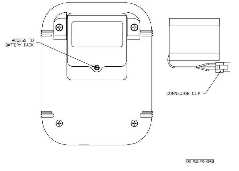
2.6 Battery Pack Replacement. In the event that a battery pack will not remain
charged and needs replacement then refer to Figure 6. Place the remote on a flat surface
with the display face down exposing the battery pack compartment on the rear of the
remote. Remove the battery cover screw with a cross tip screw driver. Press down on the
battery pack connector clip on the pack in the unit. Gently remove the battery pack
connector clip and remove the battery pack. Insert the new battery pack connector clip
onto the mate within the unit ensuring that the clip snaps into place. Put the battery pack
into the battery compartment. Replace the battery cover and re-install the battery cover
screw.
FCCUM99725
March 15, 2000
Rev -
7
Figure 6. Battery Pack Replacement