Wireless eSystems RSS99745BASE User Manual
Wireless eSystems, Inc.
UserManual.wiki
>
Wireless eSystems
>
RSS99745BASE User Manual
User Manual
Navigation menu
Upload a User Manual
Namespaces
Wiki Guide
HTML
PDF
Info
Views
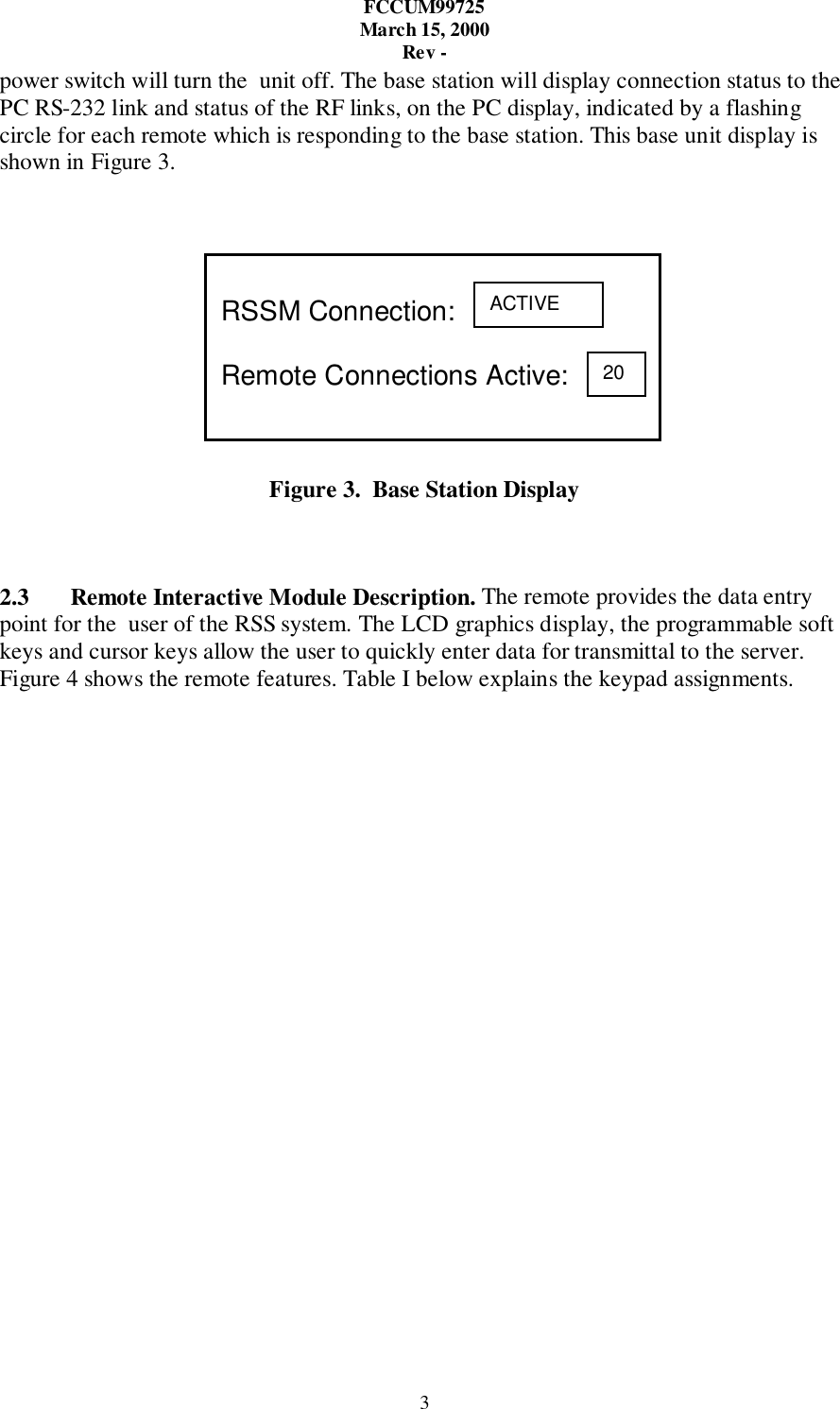
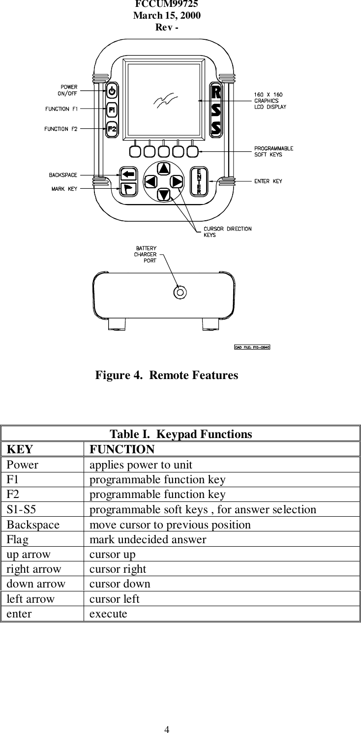
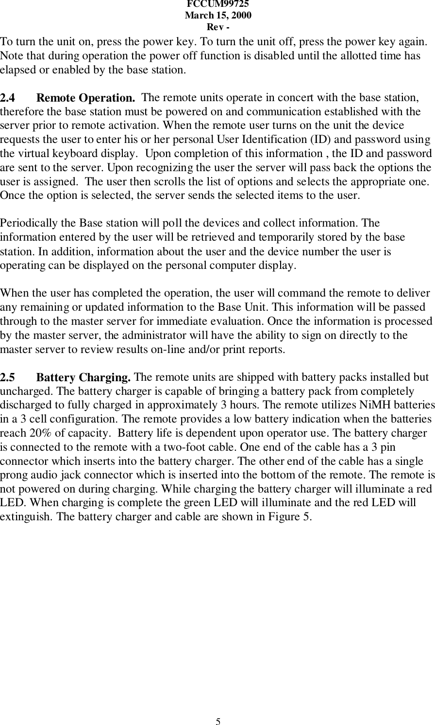
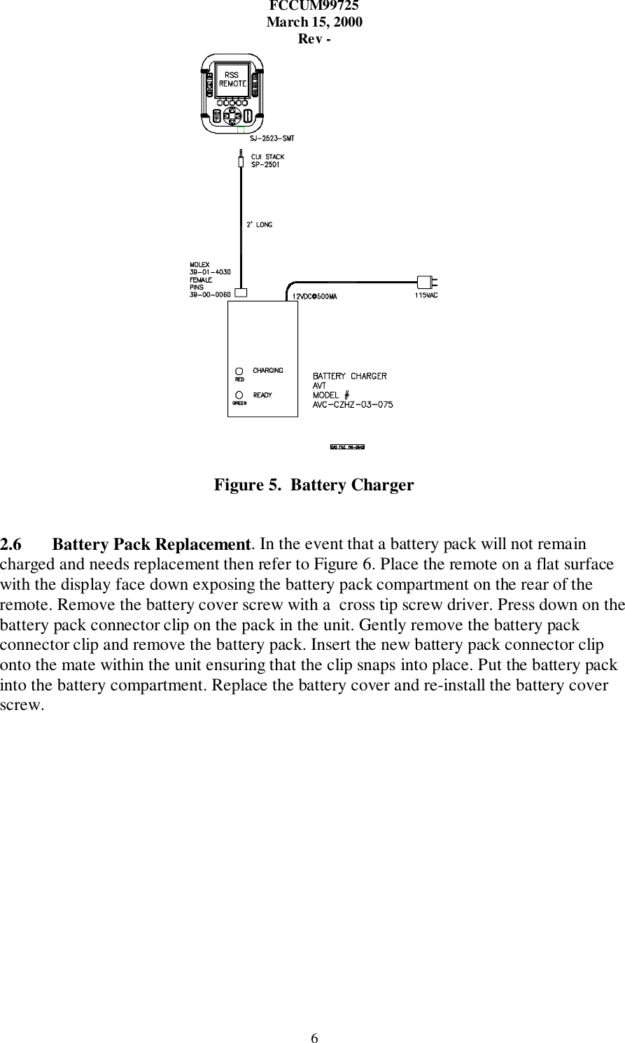
User Manual
Discussion / Help
Navigation