Wireless N2WLAX-5G7 Link AX ATM25 Extender User Manual N2 Link Cover
Wireless Inc Link AX ATM25 Extender N2 Link Cover
UserManual.wiki
>
Wireless
>
N2WLAX-5G7 User Manual
>
User Manual
Contents
1.
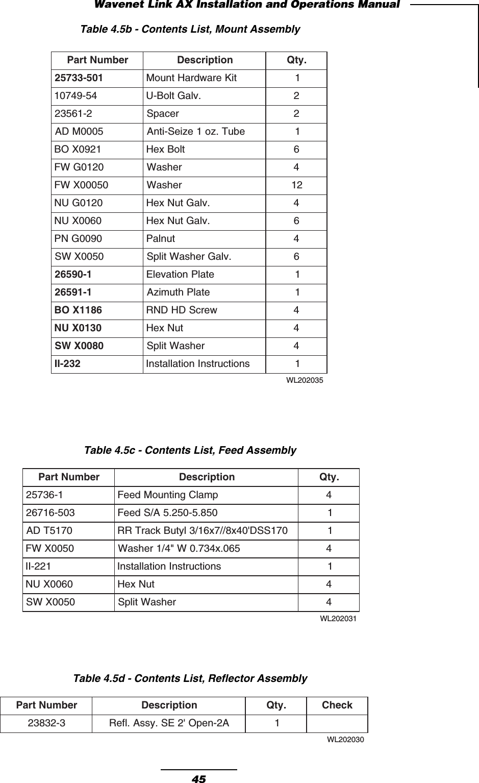
User Manual
2.
Information in user manual to comply 1515b requirements
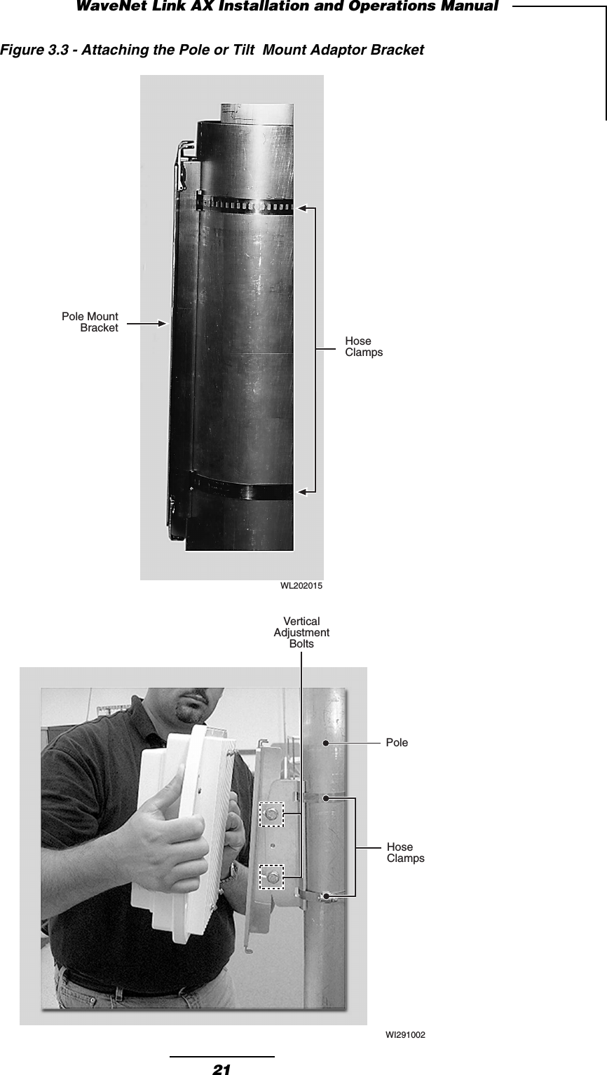
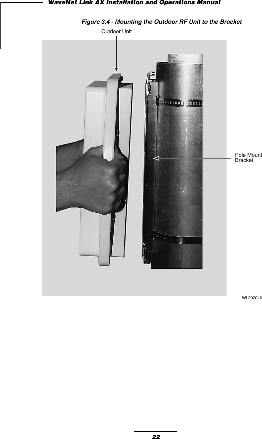
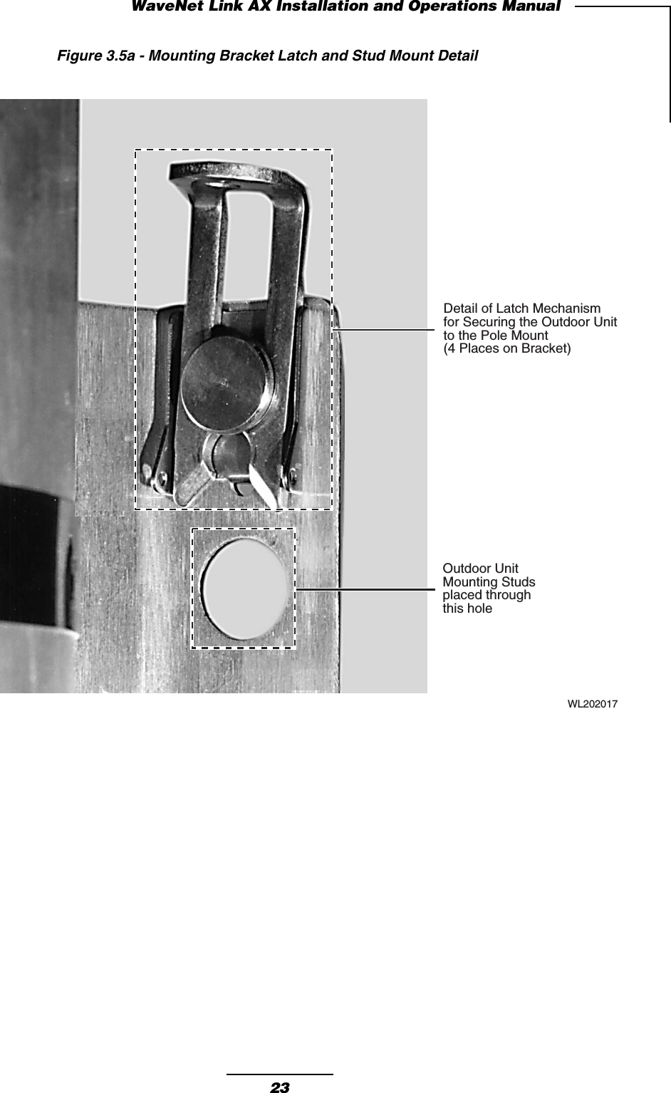
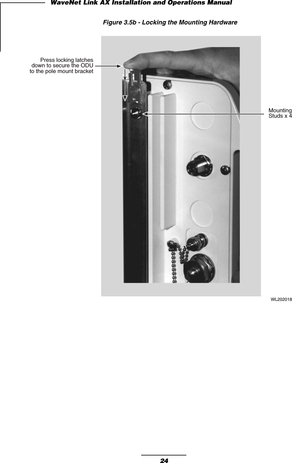
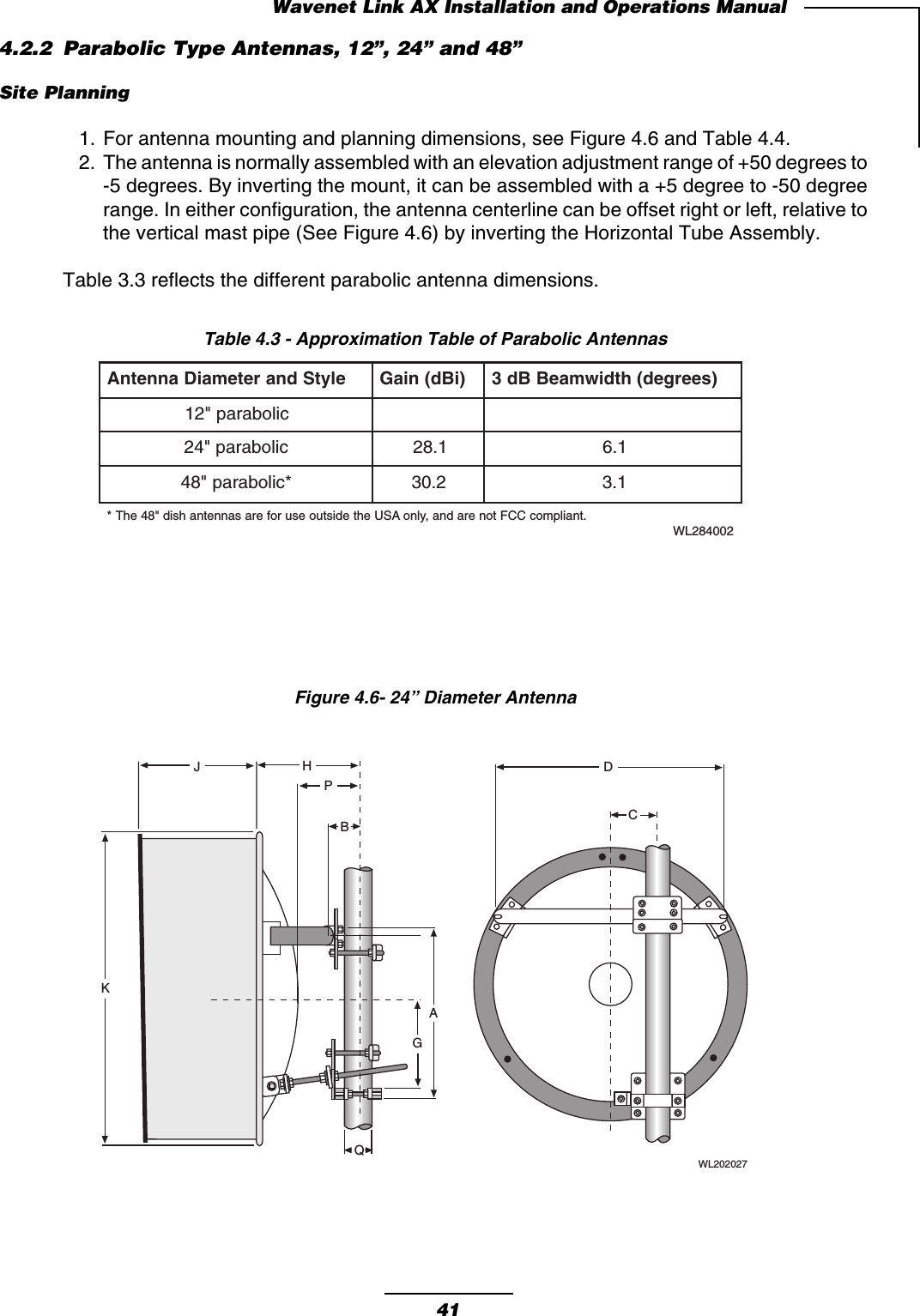
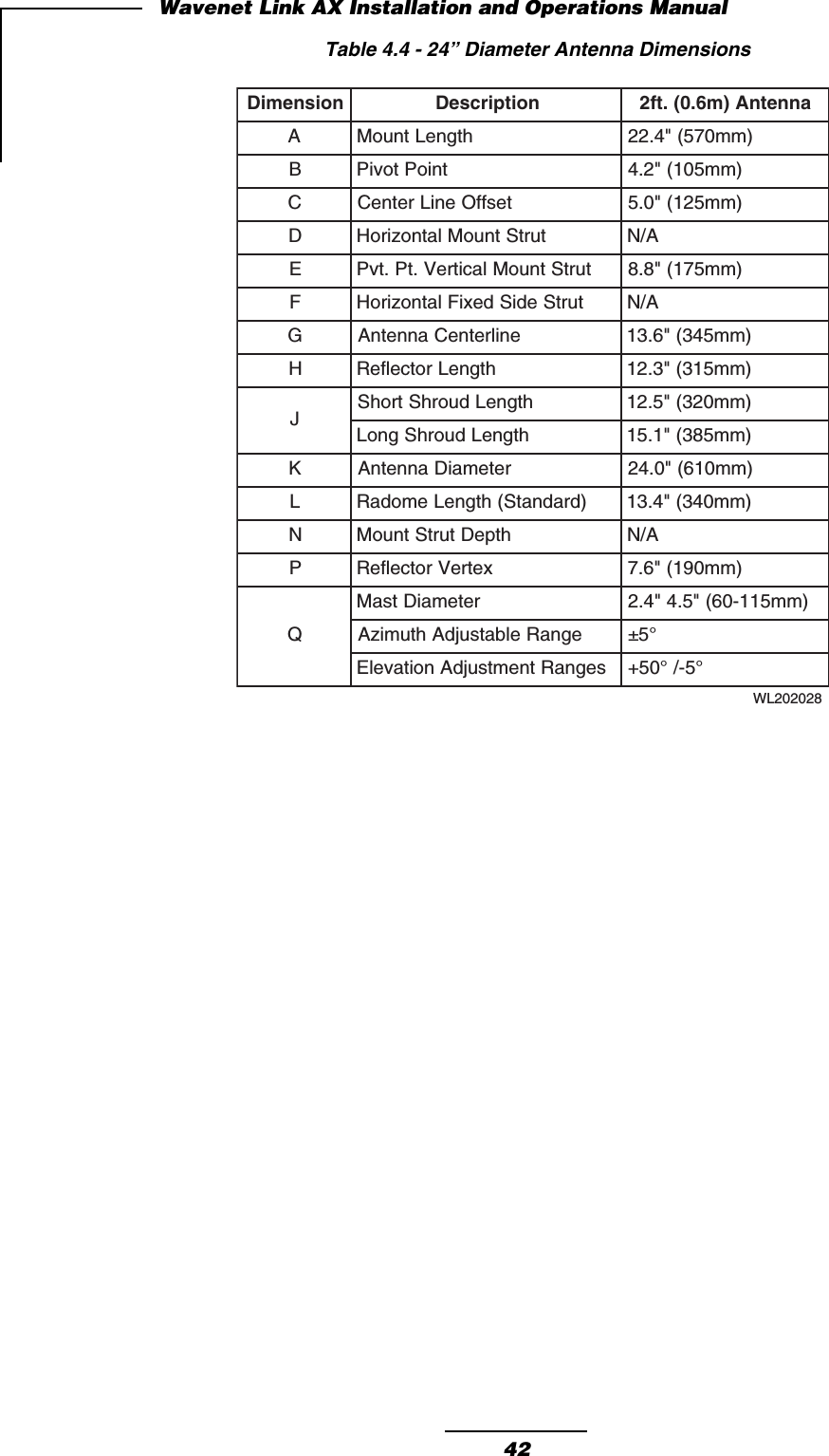
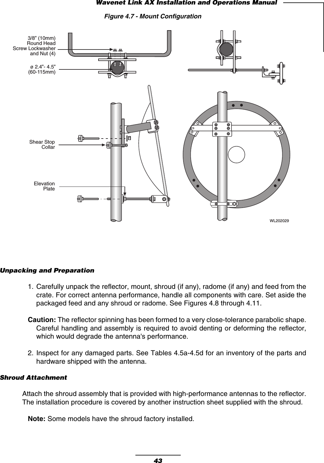
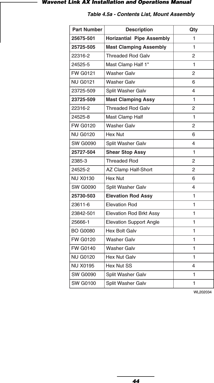
User Manual
Navigation menu
Upload a User Manual
Namespaces
Wiki Guide
HTML
PDF
Info
Views
User Manual
Discussion / Help
Navigation
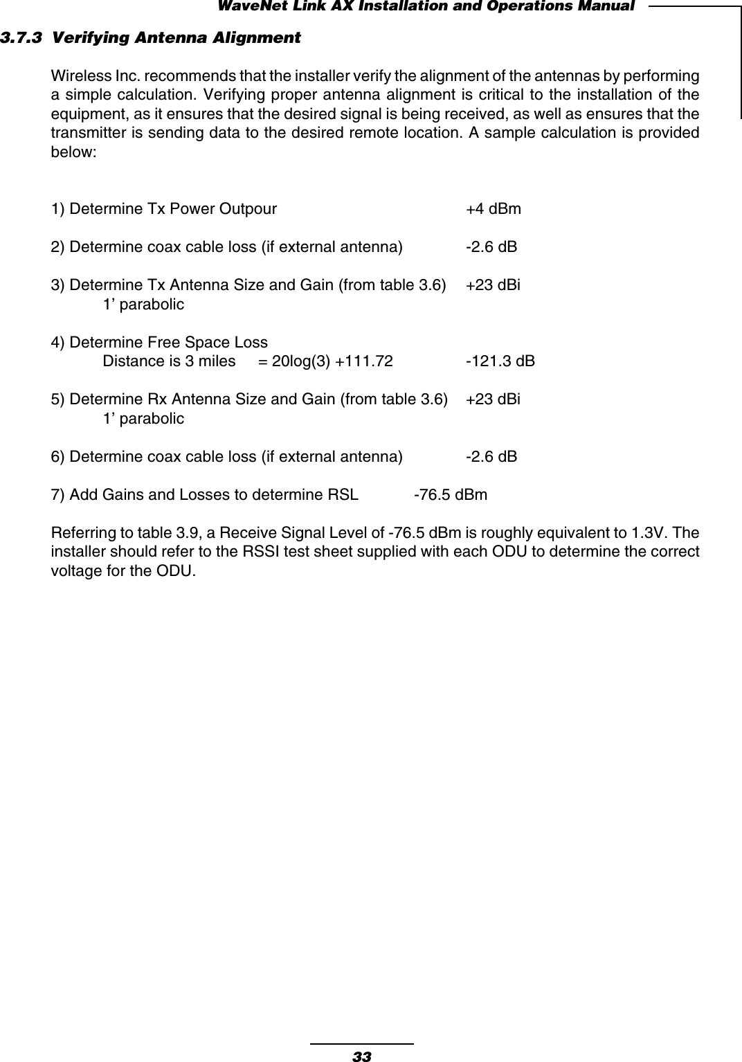
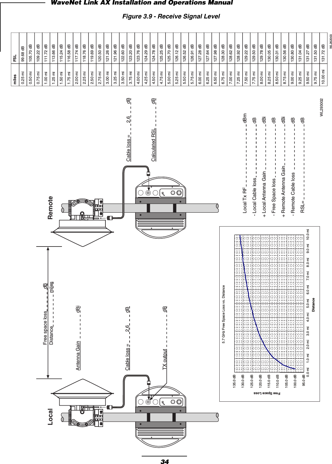
![Microwave Antenna Radiation WarningDesigned for point-to-point operation, a Link AX microwave radio system uses directionalantennas to transmit and receive microwave signals. These directional antennas are usuallycircular or rectangular in shape, and are usually mounted outdoors on a tower or mast,wellabove ground level.Referencing OET Bulletin 65 (Edition 97-01,August 1997)from the Federal CommunicationCommission ’s Office of Engineering &Technology, limits for maximum permissible exposure(MPE)to microwave signals have been adopted by the FCC for General Population/Uncon-trolled environments. This limit is 1.0 mW/cm 2 ,with averaging times of thirty-minutes.The closer you are to the front center-point of a microwave antenna,the greater the powerdensity of its transmitted microwave signal.Unless you are very close,however,microwaveexposure levels will fall far below the MPE limits.To determine how close to a microwaveantenna you can be and still remain below the MPE limits noted above,“worst case ” predictionsof the field strength and power density levels in the vicinity of an Link AX ™ microwave antennacan be made from the following calculations. The equation is generally accurate in the far-fieldof an antenna, and will over-predict power density in the near-field (i.e.close to the antenna).S =PG/4πR2where:S =power density (in mW/cm 2 )P =power input to the antenna (mW)G =power gain of the antenna in the direction of interest relative to an isotropicradiatorR =distance to the center of radiation of the antenna (cm)Note that G,the power gain factor,is usually expressed in logarithmic terms (i.e.,dB),and mustbe converted using the following equation:G =10 dBi/10For example,a logarithmic power gain of 17.5 dB is equal to a numeric gain of 56.23.Assuming (1)maximum output power from the Link AX (+12 dBm [15.8 mW ]),(2)no signal lossin the cable connecting the Link AX to the antenna,and (3)the use of a 17.5 dBi gain flat panelantenna,the 1.0 mW/cm 2 MPE power density limit would be reached at a distance ofapproximately 8.4 cm. The Link AX is classified as a fixed installation product ,and per FCCpolicy guidelines regarding MPE, antennas used for this Wireless Inc. transmitter must beinstalled to provide a separation distance of 1.5 meters (5 feet)or more from all persons duringnormal operation to satisfy FCC RF exposure compliance.Wireless,Inc. fully supports the FCC ’s adopted MPE limits, and recommends that personnelmaintain appropriate distances from the front of all directional microwave antennas. Should youhave questions about Link AX microwave signal radiation, please contact the Wireless, Inc.Customer Service Department.](https://usermanual.wiki/Wireless/N2WLAX-5G7.User-Manual/User-Guide-132981-Page-7.png)