Wirepath Home Systems 300CUB IP Camera User Manual x
Wirepath Home Systems. DBA SnapAV IP Camera x
User Manual

1
Camera
Network Cube Camera
Quick Start Guide
UD.6L0201B2047A02

Network Cube Camera·
··
·Quick Start Guide
2
Quick Start Guide
About this Manual
This Manual is applicable to 14xx Network Camera.
The Manual includes instructions for using and managing the
product. Pictures, charts, images and all other information
hereinafter are for description and explanation only. The
information contained in the Manual is subject to change, without
notice, due to firmware updates or other reasons. Please find the
latest version in the company website
Please use this user manual under the guidance of professionals.
Legal Disclaimer
REGARDING TO THE PRODUCT WITH INTERNET ACCESS, THE USE OF
PRODUCT SHALL BE WHOLLY AT YOUR OWN RISKS. OUR COMPANY
SHALL NOT TAKE ANY RESPONSIBILITES FOR ABNORMAL OPERATION,
PRIVACY LEAKAGE OR OTHER DAMAGES RESULTING FROM CYBER
ATTACK, HACKER ATTACK, VIRUS INSPECTION, OR OTHER INTERNET
SECURITY RISKS; HOWEVER, OUR COMPANY WILL PROVIDE TIMELY
TECHNICAL SUPPORT IF REQUIRED.
SURVEILLANCE LAWS VARY BY JURISDICTION. PLEASE CHECK ALL
RELEVANT LAWS IN YOUR JURISDICTION BEFORE USING THIS
PRODUCT IN ORDER TO ENSURE THAT YOUR USE CONFORMS THE
APPLICABLE LAW. OUR COMPANY SHALL NOT BE LIABLE IN THE
EVENT THAT THIS PRODUCT IS USED WITH ILLEGITIMATE PURPOSES.
IN THE EVENT OF ANY CONFLICTS BETWEEN THIS MANUAL AND THE
APPLICABLE LAW, THE LATER PREVAILS.

Network Cube Camera·
··
·Quick Start Guide
3
Regulatory Information
FCC Information
Please take attention that changes or modification not expressly
approved by the party responsible for compliance could void the
user’s authority to operate the equipment.
FCC compliance: This equipment has been tested and found to
comply with the limits for a Class B digital device, pursuant to part
15 of the FCC Rules. These limits are designed to provide reasonable
protection against harmful interference in a residential installation.
This equipment generates, uses and can radiate radio frequency
energy and, if not installed and used in accordance with the
instructions, may cause harmful interference to radio
communications. However, there is no guarantee that interference
will not occur in a particular installation. If this equipment does
cause harmful interference to radio or television reception, which
can be determined by turning the equipment off and on, the user is
encouraged to try to correct the interference by one or more of the
following measures:
—Reorient or relocate the receiving antenna.
—Increase the separation between the equipment and receiver.
—Connect the equipment into an outlet on a circuit different from
that to which the receiver is connected.
—Consult the dealer or an experienced radio/TV technician for help.
This equipment should be installed and operated with a minimum
distance 20cm between the radiator and your body.
FCC Conditions
Network Cube Camera·
··
·Quick Start Guide
4
This device complies with part 15 of the FCC Rules. Operation is
subject to the following two conditions:
1. This device may not cause harmful interference.
2. This device must accept any interference received, including
interference that may cause undesired operation.
EU Conformity Statement
This product and - if applicable - the supplied
accessories too are marked with "CE" and comply
therefore with the applicable harmonized European
standards listed under the RE Directive 2014/53/EU, the EMC
Directive 2014/30/EU, the RoHS Directive 2011/65/EU.
2012/19/EU (WEEE directive): Products marked
with this symbol cannot be disposed of as unsorted
municipal waste in the European Union. For proper
recycling, return this product to your local supplier
upon the purchase of equivalent new equipment, or dispose of it at
designated collection points. For more information see:
www.recyclethis.info
2006/66/EC (battery directive): This product
contains a battery that cannot be disposed of as
unsorted municipal waste in the European Union.
See the product documentation for specific battery
information. The battery is marked with this symbol,
which may include lettering to indicate cadmium (Cd), lead (Pb), or
mercury (Hg). For proper recycling, return the battery to your

Network Cube Camera·
··
·Quick Start Guide
5
supplier or to a designated collection point. For more information
see: www.recyclethis.info
Industry Canada ICES-003 Compliance
This device meets the CAN ICES-3 (B)/NMB-3(B) standards
requirements.
This device complies with Industry Canada licence-exempt RSS
standard(s). Operation is subject to the following two conditions:
(1) this device may not cause interference, and
(2) this device must accept any interference, including interference
that may cause undesired operation of the device.
Le présent appareil est conforme aux CNR d'Industrie Canada
applicables aux appareils radioexempts de licence. L'exploitation est
autorisée aux deux conditions suivantes :
(1) l'appareil ne doit pas produire de brouillage, et
(2) l'utilisateur de l'appareil doit accepter tout brouillage
radioélectrique subi, même si le brouillage est susceptible d'en
compromettre le fonctionnement.
Under Industry Canada regulations, this radio transmitter may only
operate using an antenna of a type and maximum (or lesser) gain
approved for the transmitter by Industry Canada. To reduce potential
radio interference to other users, the antenna type and its gain
should be so chosen that the equivalent isotropically radiated power
(e.i.r.p.) is not more than that necessary for successful
communication.

Network Cube Camera·
··
·Quick Start Guide
6
Conformément à la réglementation d'Industrie Canada, le présent
émetteur radio peut
fonctionner avec une antenne d'un type et d'un gain maximal (ou
inférieur) approuvé pour l'émetteur par Industrie Canada. Dans le
but de réduire les risques de brouillage radioélectrique à l'intention
des autres utilisateurs, il faut choisir le type d'antenne et son gain de
sorte que la puissance isotrope rayonnée équivalente (p.i.r.e.) ne
dépasse pas l'intensité nécessaire à l'établissement d'une
communication satisfaisante.
This equipment should be installed and operated with a minimum
distance 20cm between the radiator and your body.
Cet équipement doit être installé et utilisé à une distance minimale
de 20 cm entre le radiateur et votre corps.
Safety Instruction
These instructions are intended to ensure that a user can use the
product correctly to avoid danger or property loss.
The precaution measure is divided into “Warnings” and “Cautions”
Warnings: Serious injury or death may occur if any of the warnings
are neglected.
Cautions: Injury or equipment damage may occur if any of the
cautions are neglected.

Network Cube Camera·
··
·Quick Start Guide
7
Warnings
● Proper configuration of all passwords and other security
settings is the responsibility of the installer and/or end-user.
● In the use of the product, you must be in strict compliance with
the electrical safety regulations of the nation and region. Please
refer to technical specifications for detailed information.
● Input voltage should meet both the SELV (Safety Extra Low
Voltage) and the Limited Power Source with 24 VAC or 12 VDC
according to the IEC60950-1 standard. Please refer to technical
specifications for detailed information.
● Do not connect several devices to one power adapter as
adapter overload may cause over-heating or a fire hazard.
● Please make sure that the plug is firmly connected to the power
socket. When the product is mounted on wall or ceiling, the
device shall be firmly fixed.
● If smoke, odor, or noise rise from the device, turn off the power
at once and unplug the power cable, and contact the service
center.
Cautions
Warnings Follow these
safeguards to prevent
serious injury or death.
Cautions Follow these
precautions to prevent
potential injury or material
damage.

Network Cube Camera·
··
·Quick Start Guide
8
● Make sure the power supply voltage is correct before using the
camera.
● Do not drop the camera or subject it to physical shock.
● Do not touch sensor modules with fingers. If cleaning is
necessary, use a clean cloth with a bit of ethanol and wipe it
gently. If the camera will not be used for an extended period,
replace the lens cap to protect the sensor from dirt.
● Do not aim the camera at the sun or extra bright places.
Blooming or smearing may occur (which is not a malfunction),
and affect the sensor’s endurance at the same time.
● The sensor may be burned out by a laser beam, so when any
laser equipment is in use, make sure that the surface of sensor
will not be exposed to the laser beam.
● Do not place the camera in extremely hot, cold (the operating
temperature shall be -30°C to +60°C, or -40°C to +60°C if the
camera model has an “H” in its suffix), dusty, or damp locations,
and do not expose it to high electromagnetic radiation.
● To avoid heat accumulation, ensure that there is good
ventilation to the device.
● Keep the camera away from liquids.
● While in delivery, pack the camera in its original, or equivalent,
packing, packing materials. Or packing of the same texture.
● Regular part replacement: a few parts (e.g. electrolytic
capacitor) of the equipment shall be replaced regularly
according to their average endurance. The average time varies
because of differences between operating environments and

Network Cube Camera·
··
·Quick Start Guide
9
usage history, so regular checking is recommended for all users.
Please contact your dealer for more details.
● Improper use or replacement of the battery may result in
hazard of explosion. Replace with the same or equivalent type
only. Dispose of used batteries according to the instructions
provided by the battery manufacturer.
● If the product does not work properly, please contact your
dealer or the nearest service center. Never attempt to
disassemble the camera yourself. (We shall not assume any
responsibility for problems caused by unauthorized repair or
maintenance.)

Network Cube Camera·
··
·Quick Start Guide
10
Table of Contents
1 Appearance Description ............................................................... 11
1.1 Type I & Type II Cube Camera ........................................ 11
1.2 Type III Cube Camera .................................................... 15
1.3 WPS Instruction ............................................................ 17
1.4 Wi-Fi Connection........................................................... 17
2 Installation .................................................................................... 19
2.1 Type I & Type II Cube Camera Installation ..................... 20
2.1.1 microSD Card Installation ................................... 20
2.1.2 Stand Mounting .................................................. 20
2.1.3 Ceiling Mounting ................................................ 22
2.2 Type III Cube Camera Installation .................................. 24
2.2.1 microSD Card Installation ................................... 24
2.2.2 Wall Mounting .................................................... 25
2.2.3 Stand Mounting .................................................. 28
3 Setting the Network Camera over the LAN .................................. 30
3.1 Wiring ........................................................................... 30
3.2 Activating the Camera ................................................... 31
3.2.1 Activation via Web Browser ................................ 31
3.2.2 Activation via SADP Software ............................. 32
3.3 Modifying the IP Address .............................................. 34
4 Accessing via Web Browser .......................................................... 36
Network Cube Camera·
··
·Quick Start Guide
11
1 Appearance Description
There are three cube camera appearances available for this camera
series, refer to the following chapter for details.
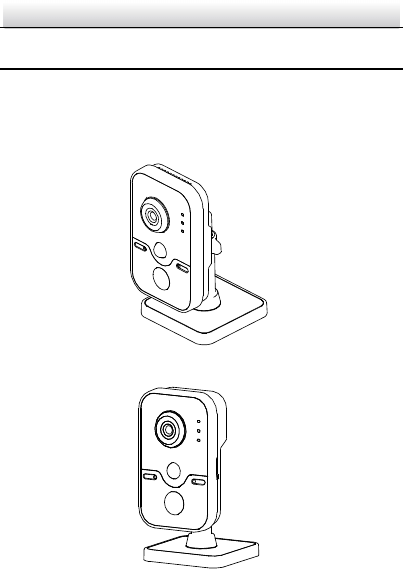
1.1 Type I & Type II Cube Camera
Figure 1-1 Type I Cube Camera
Figure 1-2 Type II Cube Camera
Network Cube Camera·
··
·Quick Start Guide
12
2
1
3
4
6
5
7
8
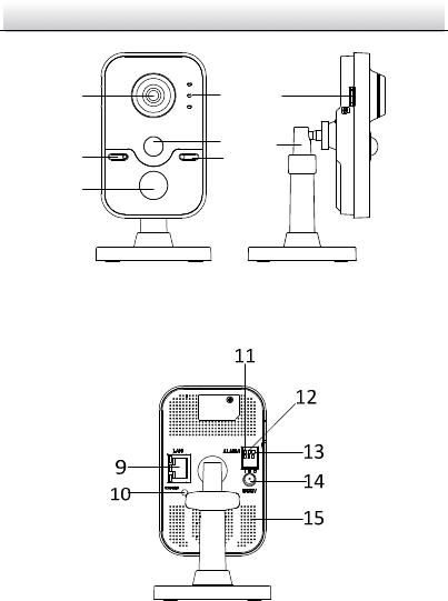
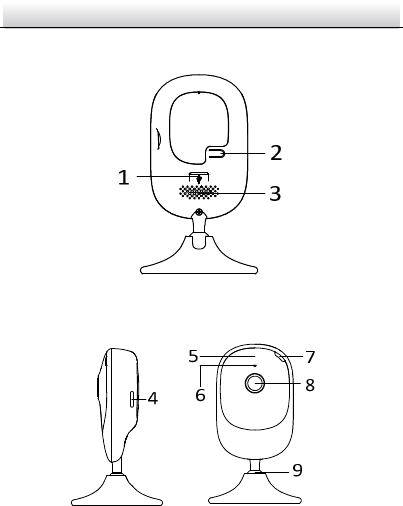
Figure 1-3 Front View and Side View of Type I and Type II Cube
Camera
Figure 1-4 Rear View of Type I Cube Camera
Network Cube Camera·
··
·Quick Start Guide
13
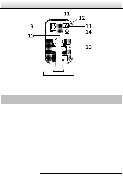
Figure 1-5 Rear View of Type II Cube Camera
Table 1-1 Description of Type I and Type II Cube Camera
No.
Description
1 Lens
2 Microphone
3 IR LED
4 Indicator
Alarm: Solid red when the camera is
armed; Solid blue when the camera is
unarmed.
Status: Solid blue when camera is working
properly; it turns to red when camera stops
work.
Link: Flashing amber when network is

Network Cube Camera·
··
·Quick Start Guide
14
No.
Description
connected; Unlit when network is
disconnected
5 PIR(Passive Infrared) sensor
6 Light Sensing
7 microSD Card Slot
8 3-axis Bracket
9 10M / 100M self-adaptive Ethernet interface & PoE
10 WPS (Wi-Fi Protected Setup)/Reset Button
11 I: Alarm Input Interface
12 G: Grounding
13 O: Alarm Output Interface
14 Power supply interface (12 VDC)
15 Speaker
Network Cube Camera·
··
·Quick Start Guide
15
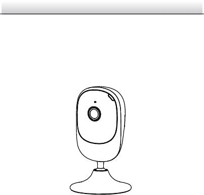
1.2 Type III Cube Camera
Figure 1-6 Type III Cube Camera
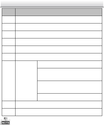
Figure 1-7 Overview of Type III Cube Camera
Table 1-2 Description of Type III Cube Camera
Network Cube Camera·
··
·Quick Start Guide
16
No. Description
1 Power Interface
2 WPS/Reset Button
3 Speaker
4 microSD Card Slot
5 IR Light
6 MIC
7 Status
Indicator
Solid red: Power on
Flashing Red: Network connected but
accessing failed
Alternative Red and Blue: Network
disconnected
Flashing Blue: Proper functioning
8 Lens
9 Adjustable Bracket
Press RESET about 10s when the camera is power on or rebooting to
restore the default settings, including the user name, password, IP
address, port No., etc.
Network Cube Camera·
··
·Quick Start Guide
17
1.3 WPS Instruction
WPS (Wi-Fi Protected Setup, also known as AOSS or QSS) is a
computing standard that attempts to allow easy establishment of a
secure wireless network.
A wireless router with the WPS function is required to enable the
WPS function of the camera.
Steps:
1. Press the WPS button on the router.
2. Press the WPS button (about 2s) on the camera within 120s you
enable the WPS of the router to join in the wireless network.
The WPS button works as a reset button only when you press it
when the camera is powering on.
Press the WPS button on the camera, and then press the WPS
button on the router will work as well, and the expire time of
WPS connection on the camera is 120s.
The link indicator blinks if the wireless connection succeeded.
1.4 Wi-Fi Connection
You can activate and manage the camera via EZVIZ Cloud P2P
platform or iVMS-4500 mobile phone client software. Refer to the
enclosed EZVIZ user manual for platform access, and refer to the
steps below for camera Wi-Fi settings with iVMS-4500 software.
Network Cube Camera·
··
·Quick Start Guide
18
Steps:
1. Connect the phone to the Wi-Fi network.
2. Install the iVMS-4500 mobile client software to the phone.
3. Open the iVMS-4500 mobile client software and enter the Wi-Fi
configuration interface to add the device.
4. Input the device serial No. or use your phone to scan the serial No.
on the device label by aligning the QR Code or Barcode with the
scanning frame.
5. Click Next and input the password (if required) of the Wi-Fi
network that your phone connects to.
6. Follow the prompts to finish the Wi-Fi connection.
7. The mobile client software obtains the device IP address
automatically after the Wi-Fi established. For the first-time login,
you are required to activate the camera first.
Refer to the iVMS-4500 User Manual for more detailed instructions.

Network Cube Camera·
··
·Quick Start Guide
19
2 Installation
Before you start:
● Make sure the device in the package is in good condition and all
the assembly parts are included.
● The standard power supply is 12 VDC or 24 VAC, please make
sure your power supply matches with your camera.
● Make sure all the related equipment is power-off during the
installation.
● Check the specification of the products for the installation
environment.
● Make sure that the wall is strong enough to withstand four
times the weight of the camera and the bracket.
For the camera that supports IR, you are required to pay attention to
the following precautions to prevent IR reflection:
● Dust or grease on the dome cover will cause IR reflection.
Please do not remove the dome cover film until the installation
is finished. If there is dust or grease on the dome cover, clean
the dome cover with clean soft cloth and isopropyl alcohol.
● Make sure that there is no reflective surface too close to the
camera lens. The IR light from the camera may reflect back into
the lens causing reflection.
● The foam ring around the lens must be seated flush against the
inner surface of the bubble to isolate the lens from the IR LEDS.
Fasten the dome cover to camera body so that the foam ring
and the dome cover are attached seamlessly.
Network Cube Camera·
··
·Quick Start Guide
20
2.1 Type I & Type II Cube Camera Installation
Type I and Type II cube camera shares the similar appearance and
installation method. Type I will be taken as an example to explain the
installation steps.
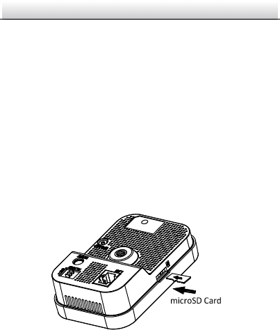
2.1.1 microSD Card Installation
This series of camera supports microSD card installation. Follow the
steps below to install the microSD card.
Steps:
1. Insert the microSD card into the card slot on the side of the
camera.
2. (Optional) Push the inserted microSD card to get it sprung out.
Figure 2-1 Install MicroSD Card
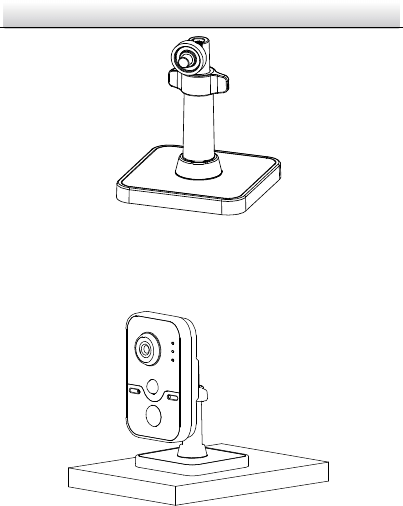
2.1.2 Stand Mounting
Steps:
1. Take the bracket out from the package.
Network Cube Camera·
··
·Quick Start Guide
21
Figure 2-2 Bracket
2. Align the camera body to the bracket, and rotate the camera
body to fix it with the bracket.
Figure 2-3 Install the Camera Body
3. Assemble the camera as the steps above, and put the camera
on the flat surface.
Network Cube Camera·
··
·Quick Start Guide
22
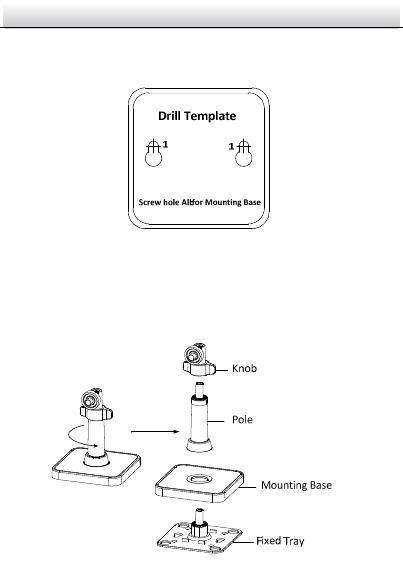
2.1.3 Ceiling Mounting
1. Drill the screw holes according to the drill template.
Figure 2-4 Drill Template
2. Disassemble the 3-axis bracket. Hold the base with one hand, and
rotate the pole anticlockwise to disassemble the pole from the
base.
Figure 2-5 Disassemble the Bracket
3. Install the fixed tray to the ceiling with the supplied screws.
Network Cube Camera·
··
·Quick Start Guide
23
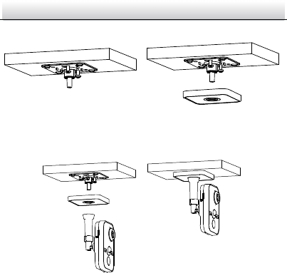
4. Install the base to the fixed plate.
Figure 2-6 Install the Fixed Plate and Mounting Base
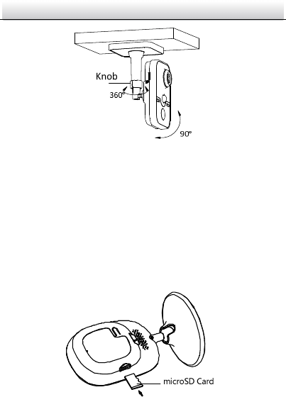
5. Install the camera to the bracket.
Figure 2-7 Install the Camera
6. Adjust surveillance angel
(1) Loosen the knob to adjust the panning angle from 0° to 360°.
(2) Adjust the tilting angle from 0° to 90°.
(3) After adjusting the angle of the camera to the desired
position, fasten the knob.
Network Cube Camera·
··
·Quick Start Guide
24
Figure 2-8 Adjust the Camera
2.2 Type III Cube Camera Installation
2.2.1 microSD Card Installation
Steps:
1. Insert the microSD card into the card slot on the side of the
camera.
2. (Optional)Push the inserted microSD card to get it sprung out.
Figure 2-9 Install microSD Card
Network Cube Camera·
··
·Quick Start Guide
25
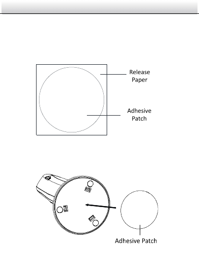
2.2.2 Wall Mounting
Steps:
1. Take out the adhesive patch from the package. Tear off the release
paper on one side.
Figure 2-10 Tear off the Release Paper
2. Attach the adhesive patch to the mounting base.
Figure 2-11 Attach the Patch
Network Cube Camera·
··
·Quick Start Guide
26
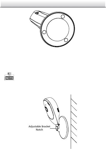
Figure 2-12 Patch Attached
3. Tear off the other piece of release paper, and stick the camera on
the wall by pressing it hard for a few seconds.
Make sure the adjustable bracket notch is upward so as to adjust
the tilt angle.
Figure 2-13 Fix the Camera
Network Cube Camera·
··
·Quick Start Guide
27
4. Adjust the surveillance angle.
1) Rotate the camera body to adjust panning position.
Figure 2-14 Adjust Panning Angle
2) Pull and push the camera body to adjust it to the desired
tilting position.
Figure 2-15 Adjust Tilting Angle
Network Cube Camera·
··
·Quick Start Guide
28
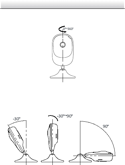
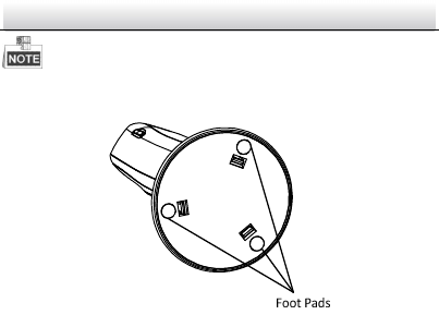
2.2.3 Stand Mounting
Steps:
1. Take out the camera from the package.
2. Select a flat surface and put the camera on, or fix the camera to
the surface with the supplied double faced adhesive tape.
Figure 2-16 Stand Mounting
3. Adjust surveillance angle.
1) Hold the mounting base and rotate the camera body to adjust
panning angle from 0° to 360°.
2) Hold the mounting base. Pull and push the camera body to
adjust the tilting angle from -30° to 90°.
Network Cube Camera·
··
·Quick Start Guide
29
The foot pads on mounting base increases friction for firm standing.
Figure 2-17 Foot Pads
Network Cube Camera·
··
·Quick Start Guide
30
3 Setting the Network Camera over the
LAN
● The use of the product with Internet access might be under
network security risks. For avoidance of any network attacks and
information leakage, please strengthen your own protection. If the
product does not work properly, please contact with your dealer
or the nearest service center.
● Chapter 3 only applies to type I & type II cube camera.
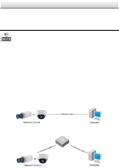
3.1 Wiring
Please connect to the camera to the network according to the
following figures.
Figure 3-1 Connecting Directly
Figure 3-2 Connecting via a Switch or a Router
Network Cube Camera·
··
·Quick Start Guide
31
3.2 Activating the Camera
You are required to activate the camera first by setting a strong
password for it before you can use the camera.
Activation via Web browser, activation via SADP, and activation via
client software are all supported. We will take Activation via Web
Browser and Activation via SADP software as examples to introduce
the camera activation. Refer to Network Camera User Manual for
activation via client software.
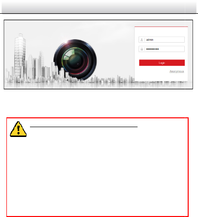
3.2.1 Activation via Web Browser
Steps:
1. Power on the camera, and connect the camera to the network.
2. Input the IP address into the address bar of the web browser, and
click Enter to enter the activation interface.
● The default IP address of the camera is 192.168.1.64.
● For the camera enables the DHCP by default, the IP address is
allocated automatically. And you need to activate the camera via
SADP software and search the IP address.
Network Cube Camera·
··
·Quick Start Guide
32
Figure 3-3 Activation Interface(Web)
3.
Create a password and input the password into the password field.
STRONG PASSWORD RECOMMENDED–We highly
recommend you create a strong password of your own
choosing (using a minimum of 8 characters, including
three of the following categories: upper case letters,
lower case letters, numbers, and special characters) in
order to increase the security of your product. And we
recommend you reset your password regularly,
especially in the high security system, resetting the
password monthly or weekly can better protect your
product.
4.
Confirm the password.
5.
Click OK to save the password and enter the live view interface.
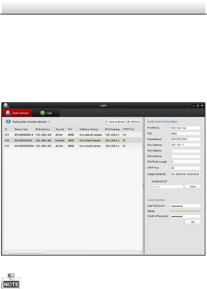
3.2.2 Activation via SADP Software
SADP software is used for detecting the online device, activating the
camera, and resetting the password.
Create a password and input the password into the password field.
SADP software is used for detecting the online device, activating the
Network Cube Camera·
··
·Quick Start Guide
33
Get the SADP software from the supplied disk or the official website,
and install the SADP according to the prompts.
Follow the steps below to activate the camera.
Steps:
1. Run the SADP software to search the online devices.
2. Check the device status from the device list, and select the
inactive device.
Figure 3-4 SADP Interface
The SADP software supports activating the camera in batch. Please
refer to SADP User Manual for details.
Network Cube Camera·
··
·Quick Start Guide
34
3.
Create a password and input the password in the password field,
and confirm the password.
STRONG PASSWORD RECOMMENDED–We highly
recommend you create a strong password of your own
choosing (using a minimum of 8 characters, including
three of the following categories: upper case letters,
lower case letters, numbers, and special characters) in
order to increase the security of your product. And we
recommend you reset your password regularly,
especially in the high security system, resetting the
password monthly or weekly can better protect your
product.
4. Click OK to save the password.
You can check whether the activation is completed on the po
pup
window. If activation failed, please make sure that the password
meets the requirement and try again.
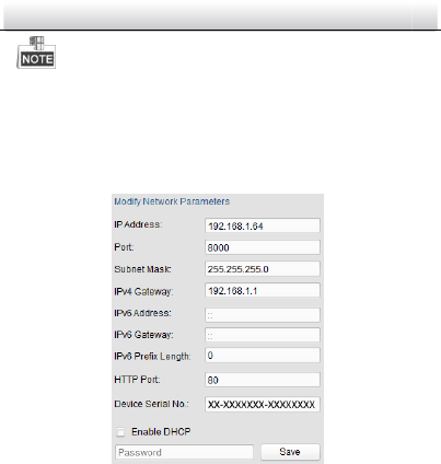
3.3
Modifying the IP Address
To view and configure the camera via the
LAN (Local Area Network),
you need to connect the network camera in the same subnet
with
your PC. Then, install the SADP software
or client software to search
and change the IP of network camera. T
ake modifying the IP Address
via SADP software as an example to introduce the IP address
modification.
Steps:
1. Run the SADP software.
2. Select an active device.
Create a password and input the password in the password field,
pup
window. If activation failed, please make sure that the password
LAN (Local Area Network),
with
or client software to search
ake modifying the IP Address
Network Cube Camera·
··
·Quick Start Guide
35
Refer to Chapter 3.2 to activate the camera if the camera is
inactive.
3. Change the device IP address to the same subnet with your
computer by either modifying the IP address manually or checking
the checkbox of Enable DHCP.
Figure 3-5 Modify the IP Address
4. Input the password to activate your IP address modification.
The batch IP address modification is
supported by the SADP; please
refer to the User Manual of SADP for details.
computer by either modifying the IP address manually or checking
supported by the SADP; please

36
4 Accessing via Web Browser
System Requirement:
Operating System: Microsoft Windows XP SP1 and above version
CPU: 2.0 GHz or higher
RAM: 1G or higher
Display: 1024×768 resolution or higher
Web Browser: Internet Explorer 8.0 and above version, Apple Safari
5.0.2 and above version, Mozilla Firefox 5.0 and above version and
Google Chrome 18 and above version
Steps:
1. Open the web browser.
2. In the browser address bar, input the IP address of the network
camera, and press the Enter key to enter the login interface.
● The default IP address is 192.168.1.64.
● For the camera enables the DHCP by default, the IP address is
allocated automatically.
● If the camera is not activated, please activate the camera first
according to Chapter 3.2.
3. Input the user name and password.
The admin user should configure the device accounts and
user/operator permissions properly. Delete the unnecessary
accounts and user/operator permissions.
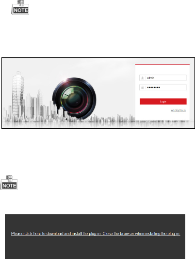
37
The IP address gets locked if the admin user performs 7 failed
password attempts (5 attempts for the user/operator).
4. Click Login.
Figure 4-1 Login Interface
5. Install the plug-in before viewing the live video and managing
the camera. Please follow the installation prompts to install the
plug-in.
You may have to close the web browser to finish the installation of
the plug-in.
Figure 4-2 Download Plug-in

38
6. Reopen the web browser after the installation of the plug-in and
repeat steps 2 to 4 to login.
For detailed instructions of further configuration, please refer to the
user manual of network camera.