Wistron NeWeb AP300G 802.11g WLAN Access Point User Manual 802 11g AP
Wistron NeWeb Corporation 802.11g WLAN Access Point 802 11g AP
UserManual.wiki
>
Wistron NeWeb
>
AP300G User Manual
Revised Manual
Navigation menu
Upload a User Manual
Namespaces
Wiki Guide
HTML
PDF
Info
Views
User Manual
Discussion / Help
Navigation


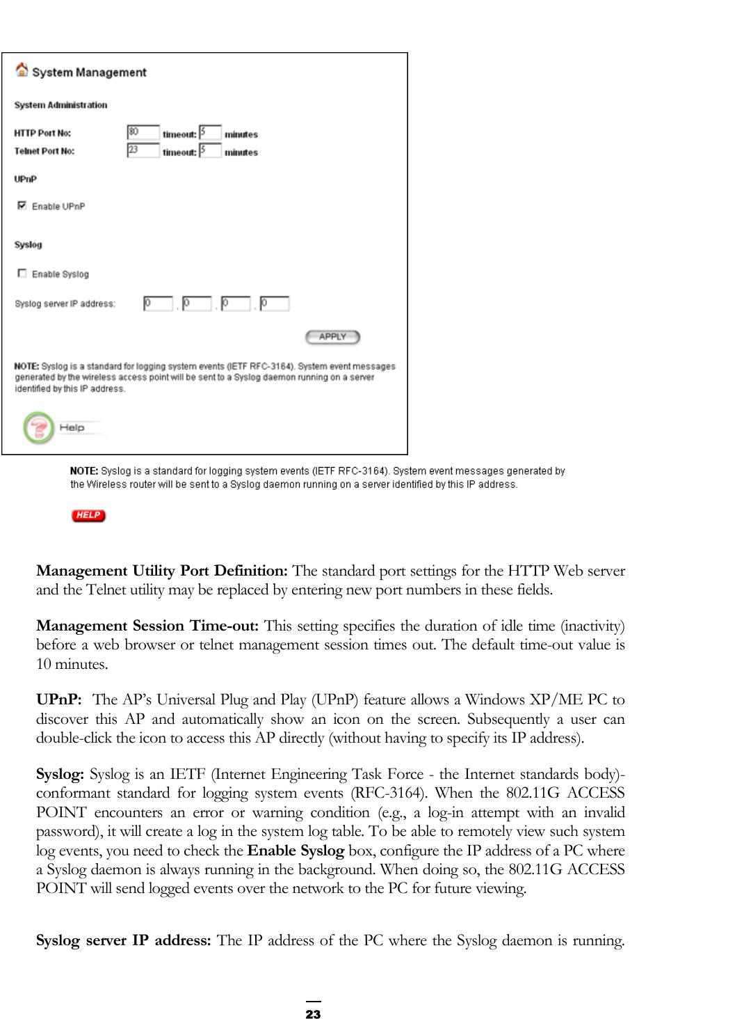
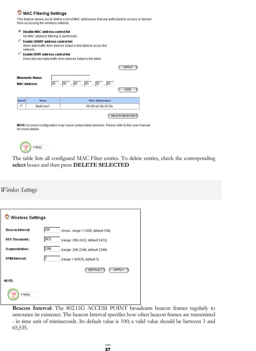

![IEEE 802.11g Access Point User’s Guide 38• If a keyword is expected when the user types “ ?”, all valid keywords will be displayed. The command typed in so far will then be displayed again along with the cursor sitting at the end, waiting for the user to continue. • If the user types in part of the keyword but does not type in the entire word, the user can then enter a tab or space for the system to automatically complete the keyword if the characters typed in so far can uniquely identify the keyword. If the characters typed in so far do not uniquely identify a keyword, a list of possible keywords will be displayed. If the user is not sure what to type next, he or she can type "?” to display the possible keywords that match the current CLI command input. If an interactive mode is entered, the system will prompt for each required parameter, such as: … select regulatory domain (fcc, fcc/etsi/france/spain/japan): enter channel number (10, 1-14): … The first prompt means there are five choices (FCC, ETSI, France, Spain, or Japan), with FCC being the default. The second prompt means a number between 1 and 14 is expected, with 10 being the default. During the first time a particular parameter is configured, typing a carriage return will cause the default value to be selected. Otherwise, typing a carriage return means no change to the current value. Express Mode vs. Advanced Mode of operation The Command Line Interface operates in one of two modes: Express Mode or Advanced Mode. In Express Mode, not all parameters are displayed. Default values are set for those parameters not displayed in multi-line commands. In Advanced Mode, users have the option to modify all possible values appropriate to each operation. The user can toggle between Express Mode and Advanced Mode by typing ^E (Control-E) at any time. Normally, the system prompt will be changed by appending “>>” to the configured prompt when in Advanced Mode. Conventions The following notations will be used: lan means the LAN port; wlan means the Wireless port; <> specifies the arguments of the command, <1-4> means a number between 1 to 4; [ ] indicates a required or optional parameter, or choice of parameters; MacAddr, or XX-XX-XX-XX-XX-XX means any MAC address in hexadecimal format, where each nn can be 00, 01, ... 99, 0A, 0B, 0C, 0D, 0E, 0F, 10, 11,… FF;](https://usermanual.wiki/Wistron-NeWeb/AP300G/User-Guide-354885-Page-38.png)
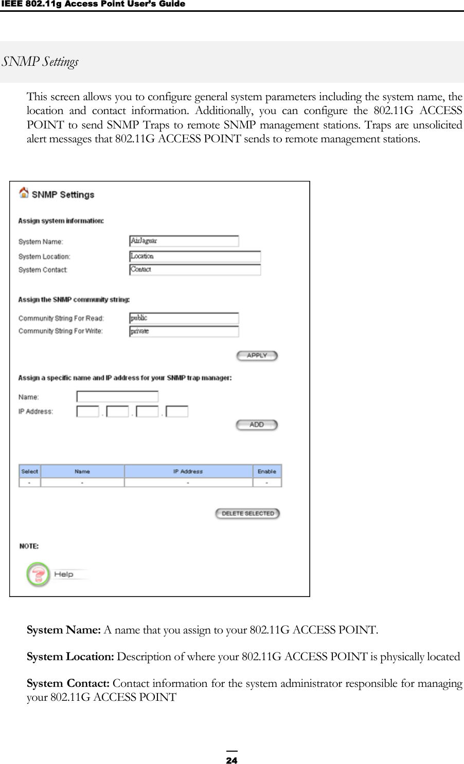
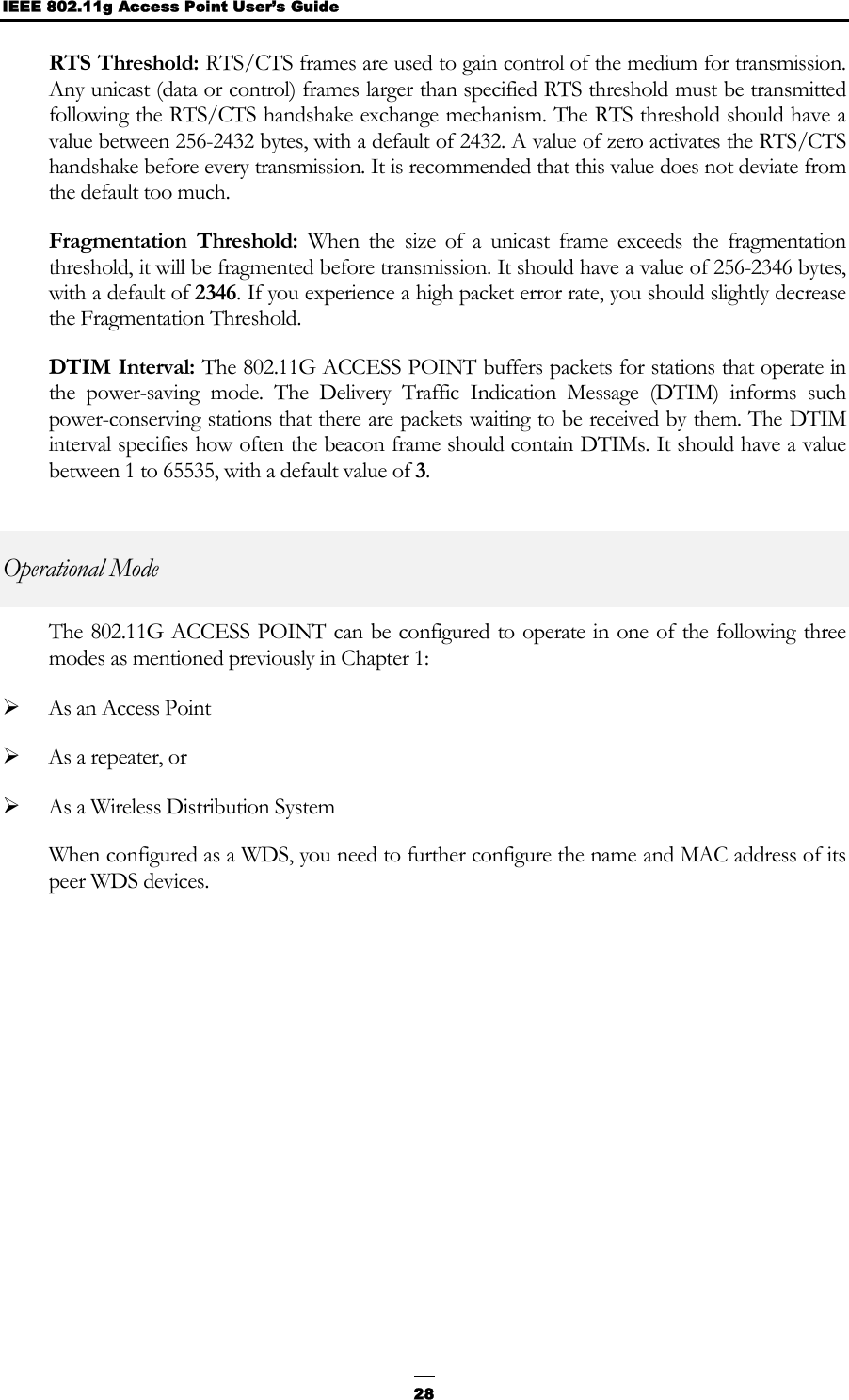
![IEEE 802.11g Access Point User’s Guide 40Wireless AP Management Console, Version: rev_no Please enter your password: ******** Logout Description: This command logs the user out of the system. Example: Command> logout Help Example: Command> help Commands are categorized as follows: (1) System (2) Port (3) Filtering (4) DHCP Server (5) SNMP (6) Diagnostics (7) Security (8) Wireless (9) Statistics Please enter a selection number [1..9] for more detailed information: Reset system Description: This command allows the user to reset the system and may cause unsaved configurations to be lost. A confirmation message will be displayed. Example: Command> reset system Warning: Reset system may cause unsaved configuration to be lost; do you want to continue (y/n)? Set telnet port <port number> Description: This command allows the user to change the Telnet service port. This information is displayed in the “show telnet” and “show system” commands. Example: Command> set telnet port 2323 Warning: Changing the port number will close existing sessions; do you want to continue (y/n)? y Telnet service port: 2323 Set telnet timeout <min> Description: This command is used to set the telnet session time-out value (in minutes). The default value is 10 minutes. This means that if the user does not type anything for 10 minutes, the telnet session will be terminated automatically. This information is displayed in the “show telnet” command.](https://usermanual.wiki/Wistron-NeWeb/AP300G/User-Guide-354885-Page-40.png)
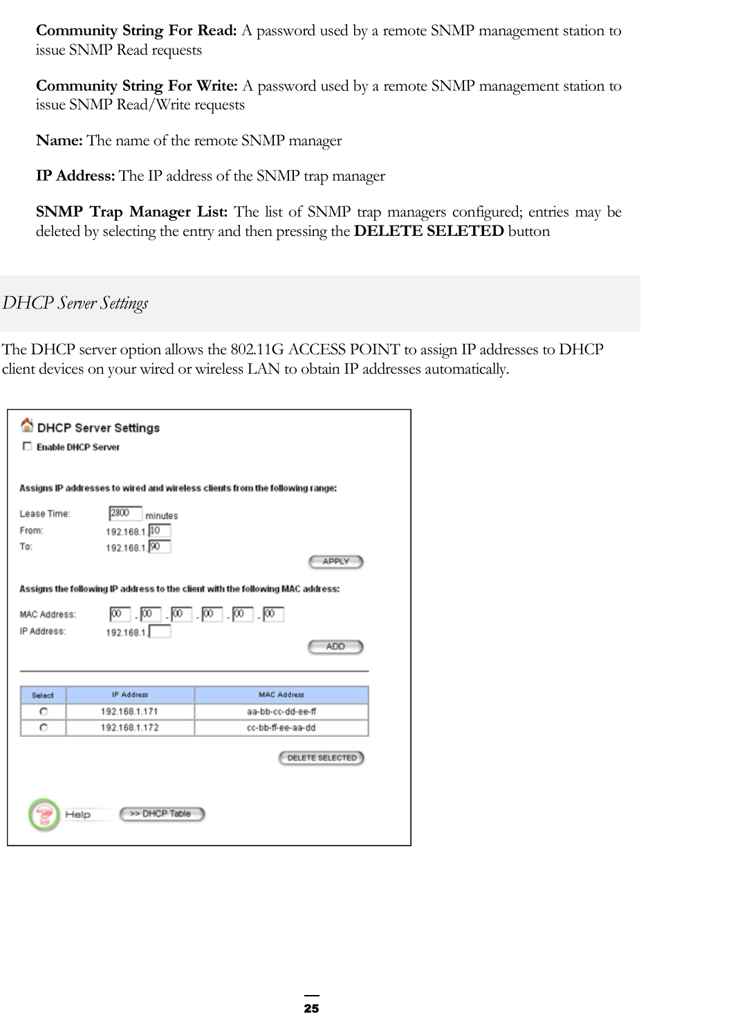
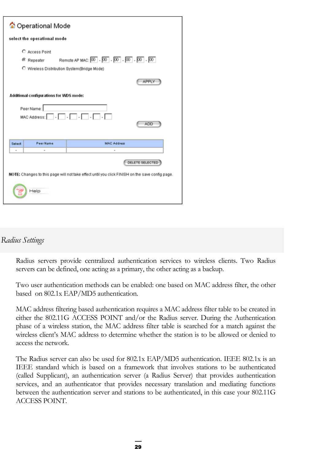
![IEEE 802.11g Access Point User’s Guide 46Port Set port wlan Description: This command configures wireless related settings Example: Command> set port wlan enter network name (WLAN): test disable SSID broadcasting (no, yes/no): select regulatory domain (fcc, fcc/etsi/france/spain/japan): fcc enter channel number (10, 1-11): 10 /* Valid channel ranges are as follows FCC: 1-11; ETSI: 1-13; France: 10-13; Spain: 1-13; Japan: 1-14; */ enable WEP encryption (no, yes/no): yes /* if WEP is enabled */ use passphrase to generate key (no, yes/no): yes select WEP key length (40, 40/128): 40 /* if passphrase is used */ enter Passphrase (Unspecified): abcde generated WEP keys with passphrase: WEP key1: XXXXX WEP key2: YYYYY WEP key3: ZZZZZ WEP key4: WWWWW select the key index to activate (1, 1-4): /* if passphrase is not used */ enter WEP key1 (Unspecified): 11111 enter WEP key2 (Unspecified): 22222 enter WEP key3 (Unspecified): 33333 enter WEP key4 (Unspecified): 44444 select the key index to activate (1, 1-4): >>> enter rts/cts threshold (2347, 256-2432): >>> enter fragment threshold (2346, 256-2346): /* must be an even integer */ >>> enter beacon interval (mini-seconds) (100, 1-1000): >>> enter DTIM interval (3, 1-65535): Show port [<lan|wlan>] Description: This command displays settings and operational information of the specified port. If “show port” is issued without any argument, it means to display the summary information of all ports. The Link State can be Up, Down, or Disabled. Example: Command> show port lan Port Name: LAN Link State: Up Link Speed: 100Mbps Duplex Mode: Full Flow Control: Enabled MAC Address: 00-01-02-03-04-05](https://usermanual.wiki/Wistron-NeWeb/AP300G/User-Guide-354885-Page-46.png)
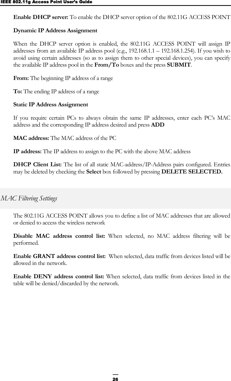
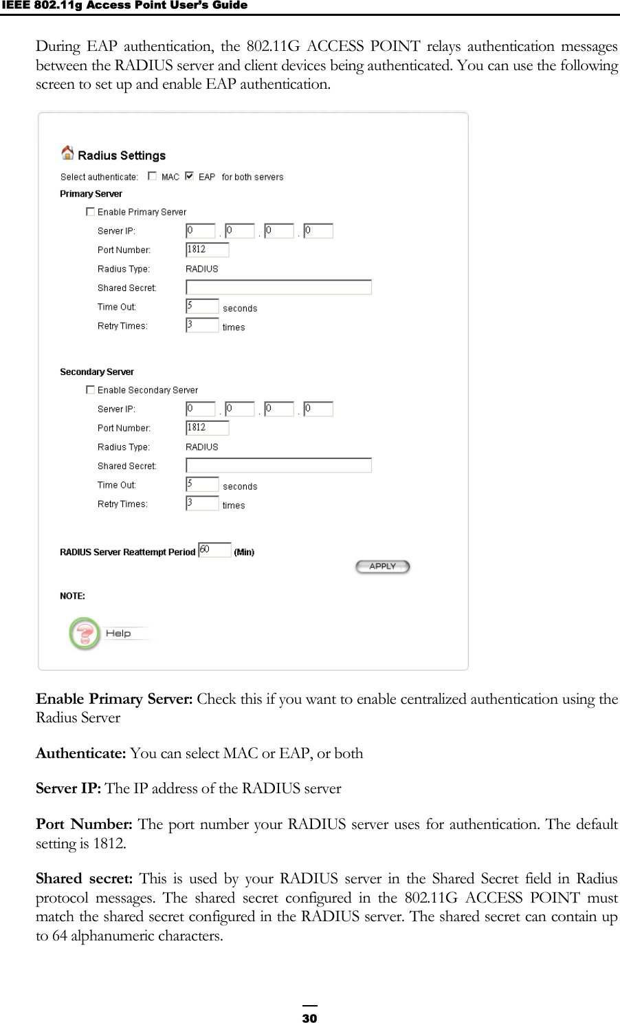
![47Example: Command> show port wlan Port Name: WLAN Link State: Up Network Name: test Disable broadcast SSID: no WLAN Mode: 802.11g Regulatory Domain: FCC Channel: 10 WEP: Enabled WEP key1: 11111 WEP key2: 22222 WEP key3: 33333 WEP key4: 44444 key index to activate: 1 rts/cts threshold: 2347 fragment threshold: 2346 beacon interval: 100 DTIM interval: 3 MAC address: 00-05-04-03-02-01 Example: Command> show port Port Name MAC address Description State ----------------------------------------------------- lan 00-01-02-03-04-05 Up wlan 00-05-04-03-02-01 802.11g Up If no argument is used, it means all ports. Show port statistics [<lan|wlan>] Example: Command> show port statistics lan Received Transmitted ----------------------------------------------------- Good Transmitted Packets 0 Good Received Packets 0 Bad Transmitted Packets 0 Bad Received Packets 0 Transmit Abort 0 Collision 0 0 Dropped Packets 0 0 Example: Command> show port statistics wlan Received Transmitted ----------------------------------------------------------- Total Octets: 98830 64171 Total Packets: 2177 198 Total Error: 0 3 [Reason for Receive Discards]](https://usermanual.wiki/Wistron-NeWeb/AP300G/User-Guide-354885-Page-47.png)
![IEEE 802.11g Access Point User’s Guide 48No Buffer: 0 Received WEP Errors: 0 Frame Checksum Errors: 340856 [Reason for Transmit Discards] Wrong Source Address: 0 Retry Limit Exceeded: 3 Other Reasons: 0 Example: Command> show port statistics Port Received Transmitted Error Name Frames Frame Frames ----------------------------------------------------- lan 324246 451526 0 wlan 2626 37343 0 If no argument is used, it means all ports. Clear port statistics <lan|wlan|all> Description: This command clears traffic statistics for a specified port or all ports. The argument “all” is used to clear all ports’ statistics. Example: Command> clear port statistics wlan statistics counter of wlan cleared. Filtering Set mac filter mode <disabled|grant|deny> Description: This command configures the operational mode of the MAC filter in the system. When MAC filtering is enabled and configured as “deny”, the frame will be filtered (denied) if the source MAC address of a received frame matches any entry in the MAC filter table. When MAC filtering is enabled and configured as “grant”, the frame will be forwarded if the source MAC address of a received frame matches any entry in the MAC filter table. Otherwise, the frame will be filtered. Example: Command> set mac filter mode grant MAC filter mode: grant Show mac filter mode Description: This command shows the operational mode of the MAC filtering feature configured in the system. Example: Command> show mac filter mode MAC filter mode: grant Add mac filter <name> <mac>](https://usermanual.wiki/Wistron-NeWeb/AP300G/User-Guide-354885-Page-48.png)
![49Description: This command adds or modifies an entry in the system MAC filter table. The total number of entries in the MAC filtering table in this version of the firmware is thirty-two. The checking is done against the source MAC address of an Ethernet packet. MAC Filters are referred to by names. Example: Command> add mac filter John 90-00-12-34-56-78 Filter Name MAC Address ------------------------------------ John 90-00-12-34-56-78 Delete mac filter <name> Description: This command deletes an entry in the system MAC filter rule by name. Example: Command> delete mac filter John MAC filter John is deleted. Show mac filter [<name>] Description: This command shows all or the specified entry in the system MAC filtering table. Example: Command> show mac filter John Filter Name MAC Address ------------------------------------ John 90-00-12-34-56-78 Example: Command> show mac filter Filter Name MAC Address ------------------------------------ John 90-00-12-34-56-78 Mary 00-00-12-34-56-79 If no argument is used, it means all MAC filter entries. DHCP Server Set DHCP server Description: This command sets the range of IP addresses (to be assigned to DHCP clients), the lease time and the DNS addresses to be used. The default lower bound is the configured system IP plus one. For example, if the configured IP subnet is 192.168.1.1/255.255.255.0, then the default lower bound for dynamic assignment is 192.168.1.2. The default upper bound is the broadcast address value minus one (255 – 1) which, in this example, is 192.168.1.254. Example:](https://usermanual.wiki/Wistron-NeWeb/AP300G/User-Guide-354885-Page-49.png)
![53Command> add trap manager SanJose 203.23.12.71 Trap Manager IP Address Status --------------------------------------------- SanJose 203.23.12.71 Disabled Delete trap manager <name> Description: This command deletes the specified trap manager. Command> delete trap manager SanJose trap manager SanJose is deleted. Enable/disable trap manager <name> Description: This command is used to enable/disable the specified trap manager. When all trap managers are disabled, no SNMP trap messages will be generated. Show trap manager [<name>] Description: This command displays trap managers that are currently defined. If a name is specified, only that trap manager is displayed. Example: Command> show trap manager Trap Manager IP Address Status --------------------------------------------- SanJose 11.22.33.44 Disabled Taipei 55.66.77.88 Disabled Show snmp statistics Example: Command> show snmp statistics Received Transmitted ---------------------------------------------- Total Packets 0 0 Request Variables 0 SET Variables 0 GETRequests 0 GETNEXT Requests 0 GET-RESPONSEs 0 0 Errors: Bad Versions 0 Bad Community Uses: 0 ASN1 Parse Errors 0 Packet Too Long 0 NO-SUCH-NAME Errors 0 BAD-VALUE Errors 0 READ-ONLY Errors 0 GENERAL-ERR Errors 0 Diagnostics](https://usermanual.wiki/Wistron-NeWeb/AP300G/User-Guide-354885-Page-53.png)
![IEEE 802.11g Access Point User’s Guide 54Ping <ipAddr> [<n_times> <n_size>] Description: This command allows the user to ping an IP device (i.e., to send a diagnostic message to be echoed by the receiving device). If n_times and n_size are specified, the ping will be performed n_times times, each time with packet size n_size. Otherwise, ping will be invoked once with packet size equal to 56 bytes. The maximum value of n_times is 100, any value larger than this will default to 100. The maximum value of n_size is 1932, any value larger than this will default to 1932. Example: Command> ping 10.0.0.2 100 1000 Repeat times = 100, data length = 1000 Ping packets -- total: 100 sent: 100 received: 100 Command> ping 10.0.0.2 Repeat times = 1, data length = 56 Ping packets -- total: 1 sent: 1 received: 1 Set log level <1-7> Description: This command changes the system log level, causing different events to be logged into the system log table. It is used mainly for debugging purposes. The log level configured in the system corresponds to the detail level of the messages to be logged. The default log level is 3, which means all system messages defined as log level 3 or below will be logged. A setting of 7 yields the maximum detail. The log level definition is given below: ALERT 1 /* action must be taken immediately */ CRIT 2 /* critical conditions */ ERR 3 /* error conditions */ WARNING 4 /* warning conditions */ NOTICE 5 /* normal but significant condition */ INFO 6 /* informational */ DEBUG 7 /* debug level */ Show log level Description: This command shows the system log level that has been configured. Enable log <facility> [<level>] Description: This command enables system log messages associated with the specified facility (such as http, etc.). Example: Command> enable log ppp 6 Or](https://usermanual.wiki/Wistron-NeWeb/AP300G/User-Guide-354885-Page-54.png)
![55Command> enable log backup Available log facilities are “http”, “csp”, “dhcpc”, “dhcps”, “dns”, “filter”, “bridge”, “xkern”, “ipc”, “ip”, “snmp”, “upnp”, “radius” Disable log <facility> Description: This command disables system log messages associated with the specified facility. Enable trace <facility> [<level>] Description: This command enables the debug trace messages associated with the specified facility. When enabled, all log messages entered into the system log will appear in the telnet screen from which this command is issued. Disable trace <facility> Description: This command disables the debug trace messages associated with the specified facility. . Show log table [<facility>] Description: The log table contains logs of various events of interest, depending on the log level set at the time. Common events to be logged will include login, as well as certain protocol progress messages for debugging purposes. This command will display the entire log table in one command instance. However, the screen will only display 22 entries at one time. Therefore, if the table contains more than 22 entries, the screen will pause and wait for the user to press any key to continue to the next 22 entries. When the system powers up, the log is re-initialized and contains no entries. A first-in, first-out scheme is used in the log table: when the 128-entry log table is full, new entries will replace the oldest entries. Example: Apr 9 16:33:30 AirJaguar http: Login from http Apr 9 16:35:30 AirJaguar http: Logout from http Apr 9 16:39:30 AirJaguar http: Login from http Set syslogd <ip> Description: This command configures the IP address of the Syslog daemon. Example: Command> set syslogd 192.168.168.100 Enable/disable syslogd Description: Syslog is a de-facto standard logging mechanism that allows System Log entries to be sent to a remote device running a standard “Syslog Daemon” application. When enabled, the 802.11G ACCESS POINT will send system log information to the syslog daemon. Example:](https://usermanual.wiki/Wistron-NeWeb/AP300G/User-Guide-354885-Page-55.png)
![57Command> add radius server primary enter authenticatation (eap, mac/eap/both): enter server IP (unspecified): 129.1.1.1 enter port number (1812, 1-65535): enter shared secret (unspecified): enter timeout (5, 1-60): enter retry times (3, 1-10): enable primary server (yes, yes/no): Admin State: Enabled Authentication scheme: MAC Server IP: 129.1.1.1 Port number: 1812 Timeout value: 5 seconds Retry times: 3 Delete radius server <primary|secondary> Description: This command deletes the primary/secondary radius server configured in the system. Example: Command> delete radius server primary primary radius server is deleted. Enable radius server <primary|secondary> Description: This command enables the primary/secondary radius server configured in the system. Example: Command> enable radius server primary Primary radius server is enabled. Disable radius server <primary|secondary> Description: This command disables the primary/secondary radius server configured in the system. Example: Command> disable radius server primary Primary radius server is disabled. Show radius server [<primary|secondary>] Description: This command shows the primary/secondary radius server configured in the system. Example: Command> show radius server primary Admin State: Enabled Authentication scheme: MAC Server IP: 129.1.1.1 Port number: 1812 Timeout value: 5 seconds Retry times: 3 Example:](https://usermanual.wiki/Wistron-NeWeb/AP300G/User-Guide-354885-Page-57.png)